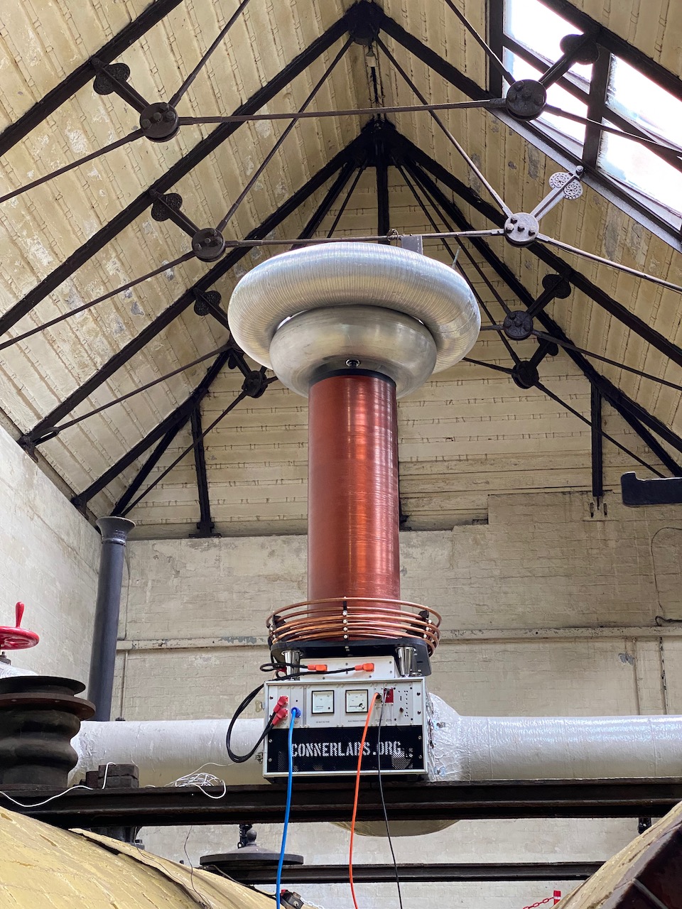
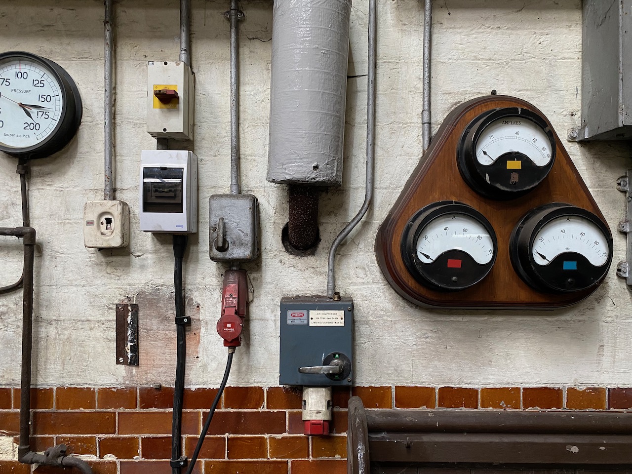
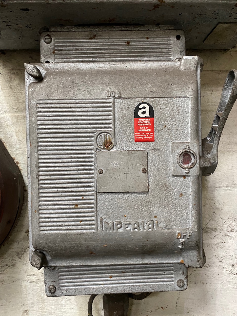
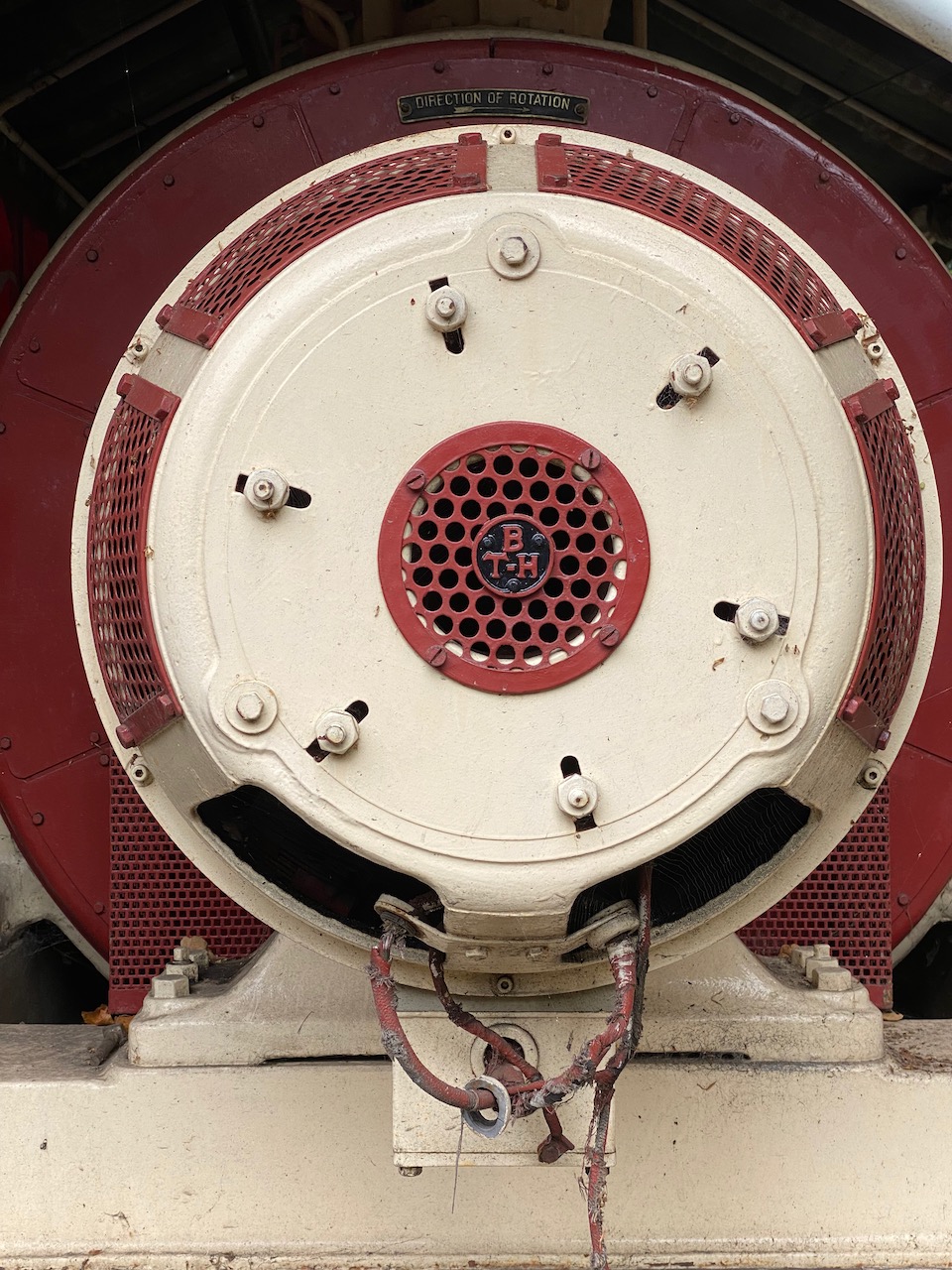
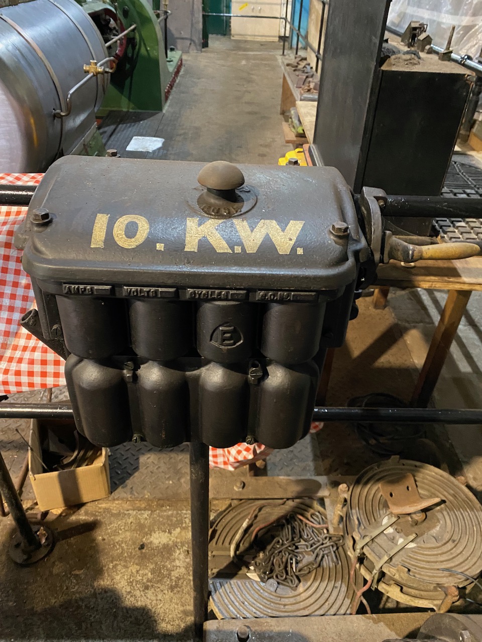
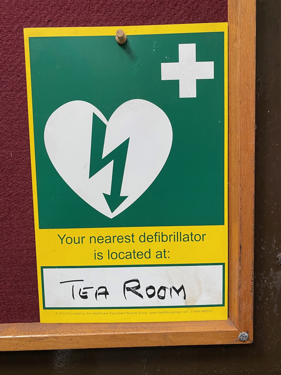
Boiler house switchboard… Yes my setup moved the meters 🙂 Mmmm, asbestosThis generator was a bit too small to power Odin 🙁This one was too bigMy performance did actually use about 10kWAn event like this would not be possible without defibrillators and a tea room.
We plugged it into the 3 phase outlet and it started up normally! 😀
When smashed with 750V the Tesla cabin heater would draw an impressive amount of power while warming up. Unfortunately the steady state power draw was only about 2kW, probably something to do with the rather weak fan cooling it.
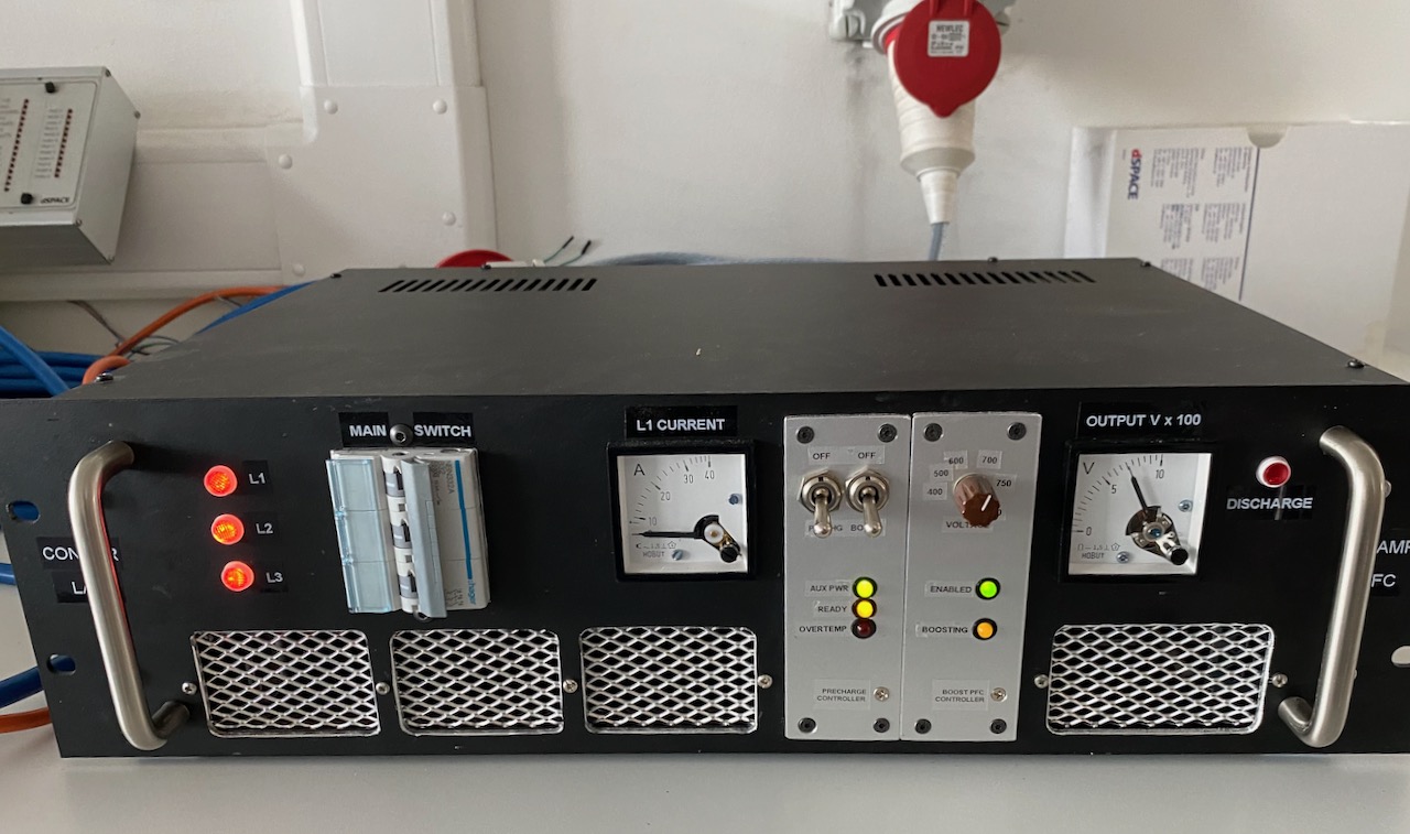
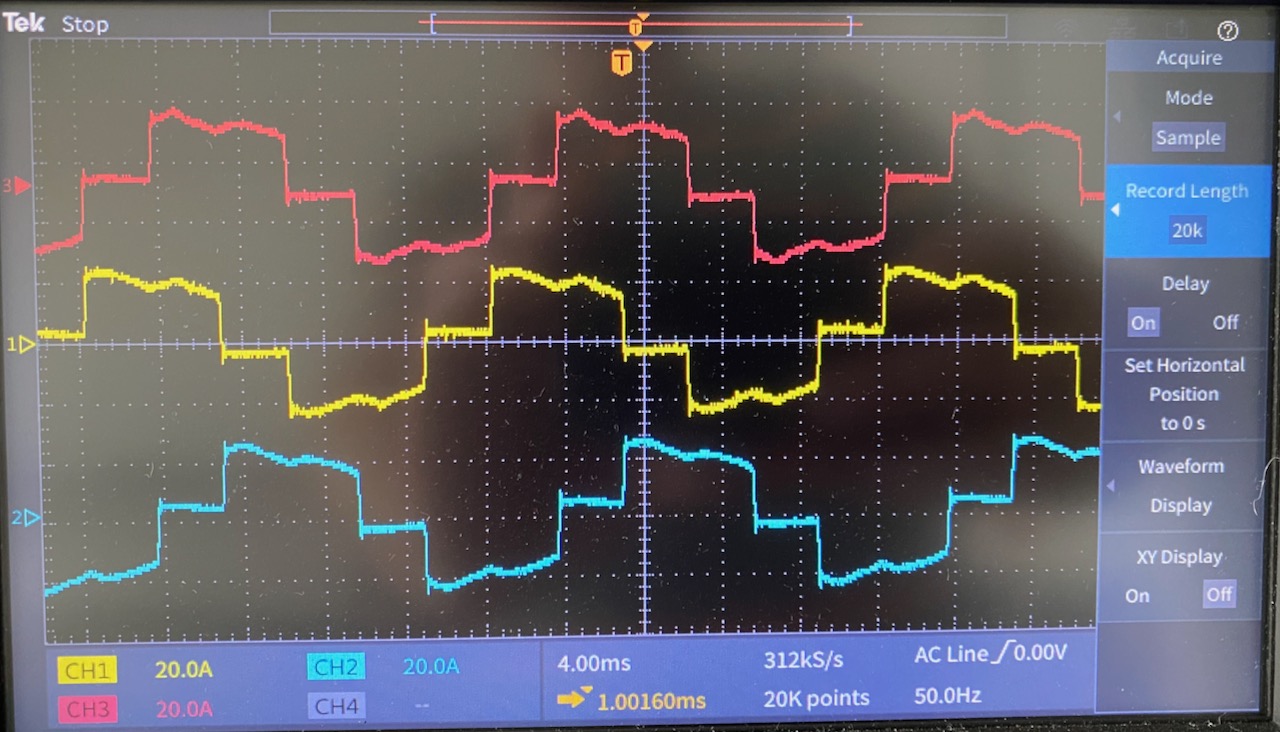
The PFC line current waveforms at (roughly) this 11kW output power level. No surprises here, they look exactly like the theoretical ones for this circuit. (Except strictly speaking the red one is upside down 🙂 ) The theoretical power factor for this waveform is 0.95.
We don’t have a 3 phase power analyser in the lab, so I used 2 single phase ones on the input, according to the old “2 wattmeter method“. To be honest this didn’t work very well, as the power drawn by the PTC heater was always changing, and it was impossible to make sure the 2 meter readings corresponded to exactly the same time. Also, the PF reading is rubbish due to the inherent 30 degree phase shift: to get the actual PF you have to plug the wattage readings into a complicated formula.
When the heater reached steady state, I measured an input power of 2000W, an output of 1900W, and a power factor of 0.96. From an academic point of view it would have been nice to measure the efficiency at higher powers, I expect that 100W is mostly switching losses and the efficiency will increase with heavier loads.
The main goal was to get confidence that the PFC would work at its first gig, and this has been achieved 🙂
Another problem I have with the cabin heater testing (And the PFC testing 🙂 ) is that the PFC is not designed to start up into a load. This isn’t a problem for the intended application, as the Tesla coil won’t draw any current until it’s commanded to. But to power a resistive load, I have to use a switch to connect the load after the PFC has started up.
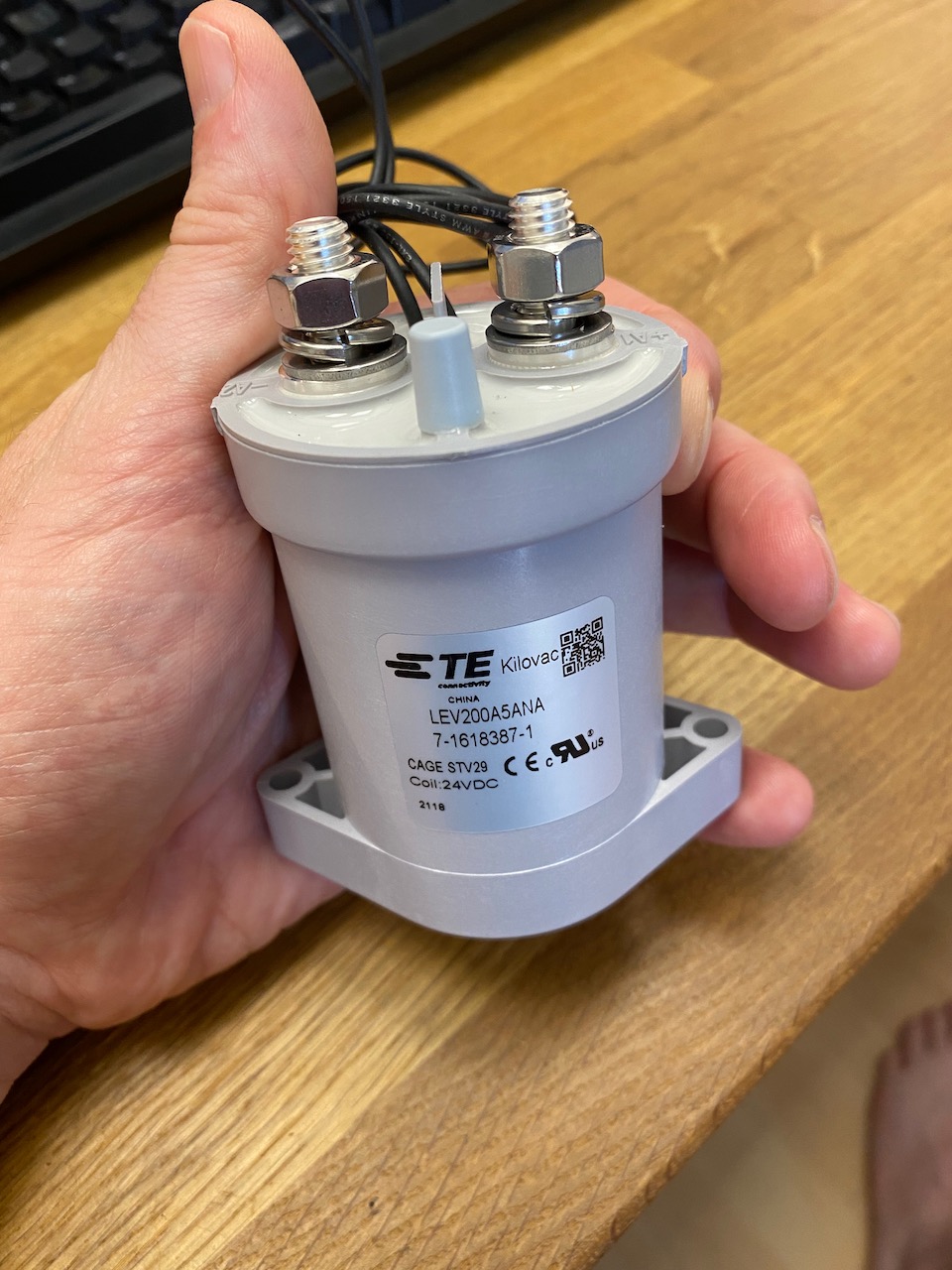
For the previous immersion heater tests I used an ordinary 240V AC rated switch. This will make a DC circuit, but won’t break it: the arc simply won’t go out until the entire switch is incinerated. Of course if you’re reading this there’s a fair chance that you actually enjoy burning things to a crisp with electric arcs, but I have to be on my best behaviour to get the keys to the 3 phase outlet at work, and proper DC rated contactors are getting cheaper anyway thanks to the proliferation of electric vehicles.
The Kilovac LEV200 has hydrogen filling and a permanent magnet to blow out the arc. It’s good for several hundred amps at 900V DC.
I thought I’d better test the characteristics of the PTC elements in a scientific manner as opposed to just applying 750V DC from the PFC and seeing what happens.
When measured with a multimeter at room temperature, each element read about 600 ohms. This would imply a rather low power output if that was the minimum resistance.
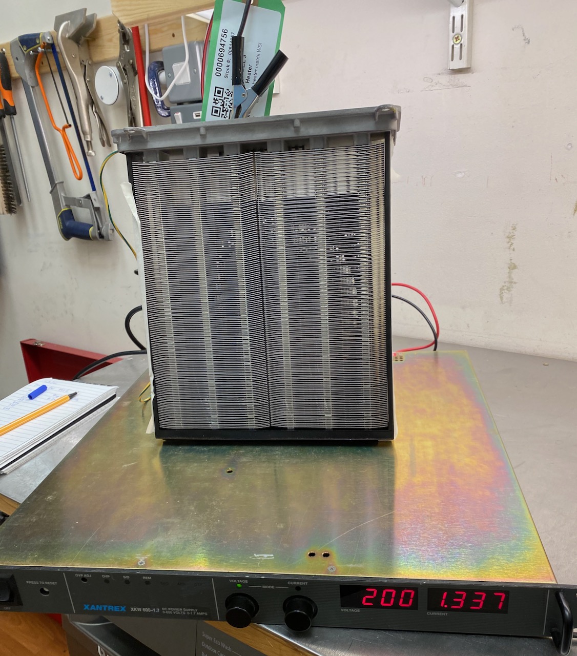
For my next experiment I connected one of the elements to my old Xantrex 600V bench power supply. The 600 ohm cold resistance would imply a draw of no more than 1A at 600V if the element was purely PTC. But to my surprise, the current draw actually began to increase as the element got hotter, eventually hitting the PSU’s 1.7A current limit at only 200V.
This means that the elements must actually start off as NTC, and transition to PTC at a higher temperature. That kind of makes sense, as a car heater matrix has to be able to start up from very low temperatures. Purely PTC elements would presumably exhibit an immense current surge when the heater is turned on after leaving the car parked overnight in Canada. 🙂
I was wondering why Tesla bothered to implement individual control of the 6 elements, and I guess the turn-on surge is the answer to this too: by turning them on sequentially the surge can be made 6x smaller. It’s not like a Tesla traction battery (or even an IGBT) would care if the turn-on surge was 10A or 60, but maybe it allows them to use a lower rated fuse to connect the heater to the battery. Fuses rated for high voltage DC are expensive so the savings made here might outweigh the cost of 5 IGBTs and drivers.
Anyway, I couldn’t test above 200V due to the limited output current. The next larger PSU I have is the PFC, and it has a minimum output voltage of 400V (600 on 3 phase) so I will just have to “send it” as the kids say nowadays.
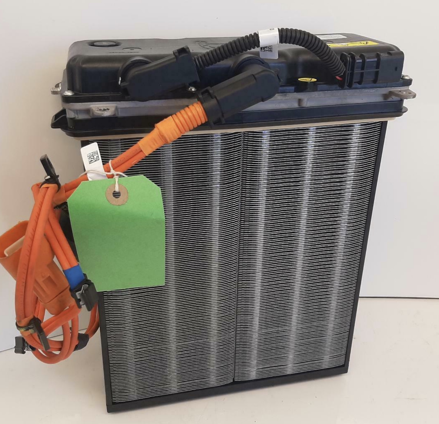
I needed a high power dummy load that was a bit more health and safety friendly than my bucket of immersion heaters. I investigated lots of possibilities until I eventually found a Tesla Model 3 heater matrix on eBay. The Internet said it could draw up to 6kW, and being PTC, it shouldn’t catch fire if I forget to turn the fan on, which would look great on a risk assessment. So I went for it. 🙂
The lid is held on by penta-lobe screws with a tamper-proof peg in the middle. There was nothing in my collection of tamper-proof bits that would fit, but a sturdy flat-bladed screwdriver worked quite well after Dremeling a new slot or just jamming it in hard enough to break off the peg. 😀
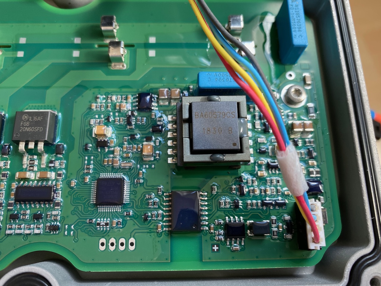
Ooh, fancy! What does all this stuff even do?
There appear to be 6 separate PTC elements, each with low side switching by a 600V IGBT and non-isolated gate driver.
To the left of the IGBTs is a voltage divider and low side current shunt, and on the right an isolated CAN interface and DC-DC converter. Handling CAN communications and A/D conversion of the voltage and current signals, we have an 8 bit ST microcontroller (probably sharing its 0V rail with DC bus negative)
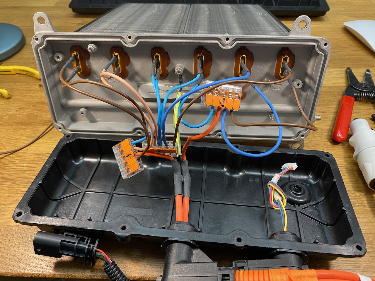
Of course I immediately set to work reverse engineering the CAN protocol so I could command it to connect its elements in 2 groups of 3 for 800V input. Oh wait that’s not gonna work 🙁 we need a hardware solution…
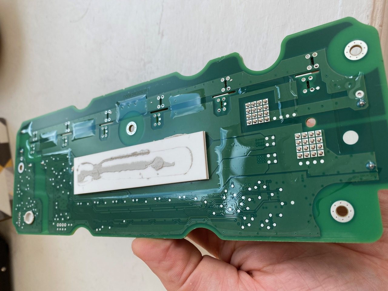
The heating elements were connected to the PCB by spring clips that released quite easily, but the PCB was stuck firmly to the aluminium enclosure with thermally conductive glue. I freed it with the old embedded programming trick of heating the enclosure with a heat gun and prying with a paint scraper. (sadly this doesn’t work any more in Python 3 😉 )
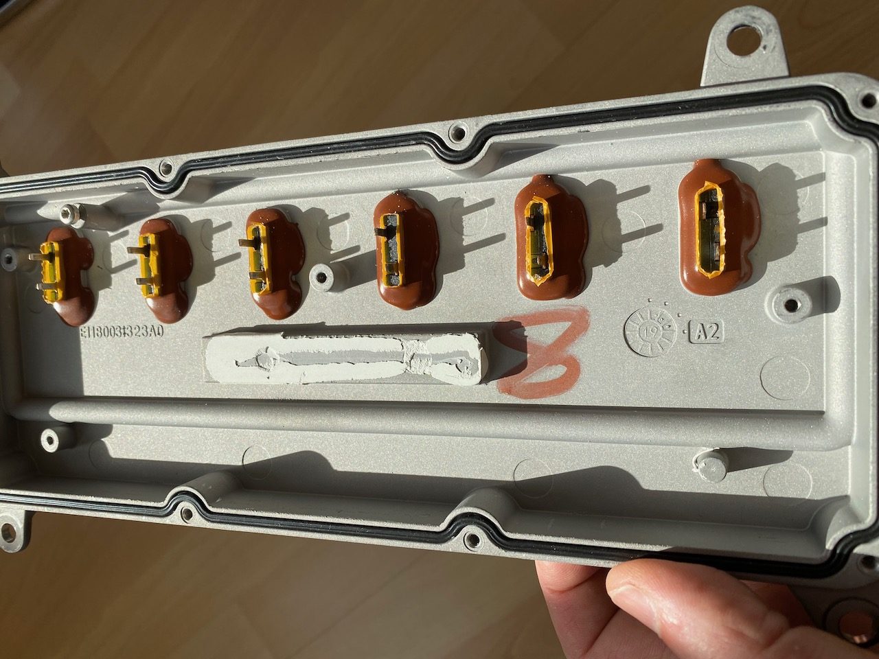
With the PCB removed we can see the terminals for the heating elements, looks as if some sort of spade terminal should fit nicely. (Also note the little nodule at bottom right which appears to be for cooling the CAN transceiver chip.)
And after a pulsating second half the score is Wago 221, CANbus 0. 😀
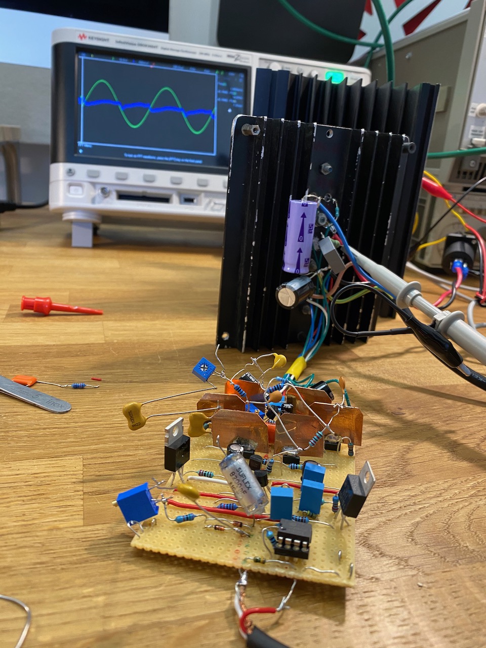
I got it to work and amplify, but the loop gain left a lot to be desired, so I decided to start over on the compensation. I also hooked up an unregulated power supply and a different output stage, partly because I wanted to see how the PSRR was doing, and partly because I wanted to reassemble the Ice Block with its original driver board.
It survived 🙂
Now, you should never anthropomorphise amplifiers, they hate it! I swear that this one “wants” to blast electronic music from the 90s at high volume though. 🙂
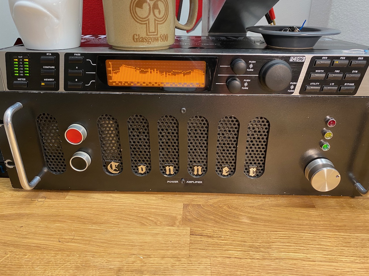
Found this in my junk pile, retro or what 🙂
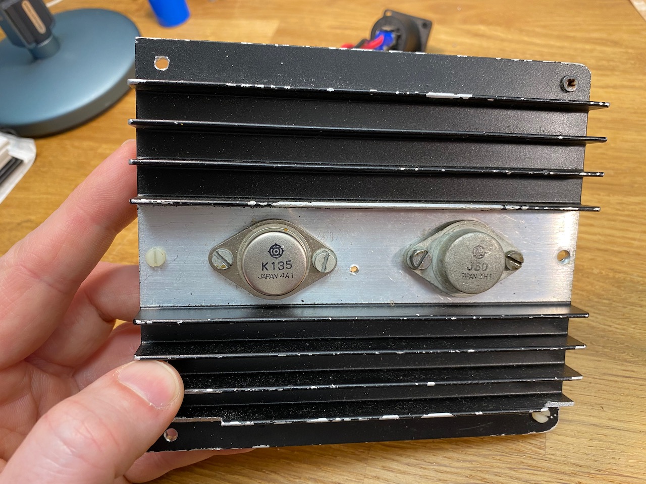
Having given the Ice Block its output stage back, I had to find another one for my experiments. A search of the junk pile yielded the remains of a Maplin 100W MOSFET amp kit. I’d have preferred to try BJTs, but the PG508 prototype was already set up to work with lateral MOSFETs.
Put it together and what have you got?
I tried the time-honoured method of soldering RC networks in random places, or maybe places that seemed to make a difference when touched with a damp finger. 🙂 This improved it somewhat, but it still wasn’t doing a great job of correcting the output stage’s copious (and vintage correct!) crossover distortion.
Cordell to the rescue!
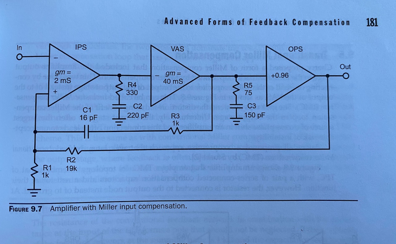
I eventually cracked Bob Cordell’s “Designing Audio Power Amplifiers” and spent an afternoon pondering Chapter 9, “Advanced Forms of Feedback Compensation”. It struck me that the PG508 topology is very similar to figure 9.7, except that the input stage doesn’t exist as such: the feedback node is the VAS input.
It also struck me that I’d already ended up with RC networks in the places shown in fig. 9.7 by trial and error, just with completely different values. R4 and C2 were in the original Tektronix PG508, and R5 C3, R3 C1 were my additions. So the obvious course of action was to change them to the values suggested by Cordell and see what happened.
Initial results weren’t great: it oscillated at 20MHz, but this was squelched by reducing R4 to 51 ohms. Having done this, performance was excellent: the 16pF C1 gave the extra loop gain I was looking for. I’d started out with 100pF here as that’s the value used in a Douglas Self Blameless amp. The Blameless input stage typically has 5-10x the gm of the PG508’s non-existent IPS, though. So funnily enough C1 needs to be 5-10x smaller to get comparable loop gain.
With these modifications the measured performance was 0.03% THD at full power at 10kHz, and 0.00something at 1kHz. The 10kHz figure seems high, but it’s now in the ballpark for a well functioning driver doing its best with a vintage MOSFET output stage. (Cordell’s AES paper quoted 0.02% at 10kHz with the Hawksford error correction turned off.)
Note that this THD figure is no better than I got with the old compensation and the Ice Block output stage. This just means that the Ice Block output stage must have about 3-5x less distortion than the single 2SK135/2SJ50 pair used here.
Slew rate was also improved, and stability with a capacitive load was just about acceptable: with 0.1uF slapped on the output it showed a few cycles of damped ringing but didn’t oscillate.
The circuit at the end of a hard day of soldering capacitors at random (and trying to find a LM317 or 7912 : ) )
I also took the opportunity to test out the opamp front end inspired by the Quad 405 and Cordell Super Gain Clone. I used an OPA2604 as it was the best opamp I had around. This works very nicely: it reduces the DC offset to 2mV, undoes the phase inversion inherent in the PG508 circuit, and increases the overall gain from 10 to 50.
Note that the opamp must be a FET input type because of the high impedance of the DC feedback path. Also, as the circuit has 2 LF time constants (the 1M/1u and the 47k/2u) with feedback around them, it functions as a 2nd order active high pass filter. It rolls off at 12dB/octave and can resonate if the time constants are too close together.
I basically copied this part from the Quad 405, so it must have done the same thing. I guess it was desirable to have a good rumble filter here in the days of vinyl. Arguably it still is in the era of small vented speaker cabinets and dubstep. 🙂
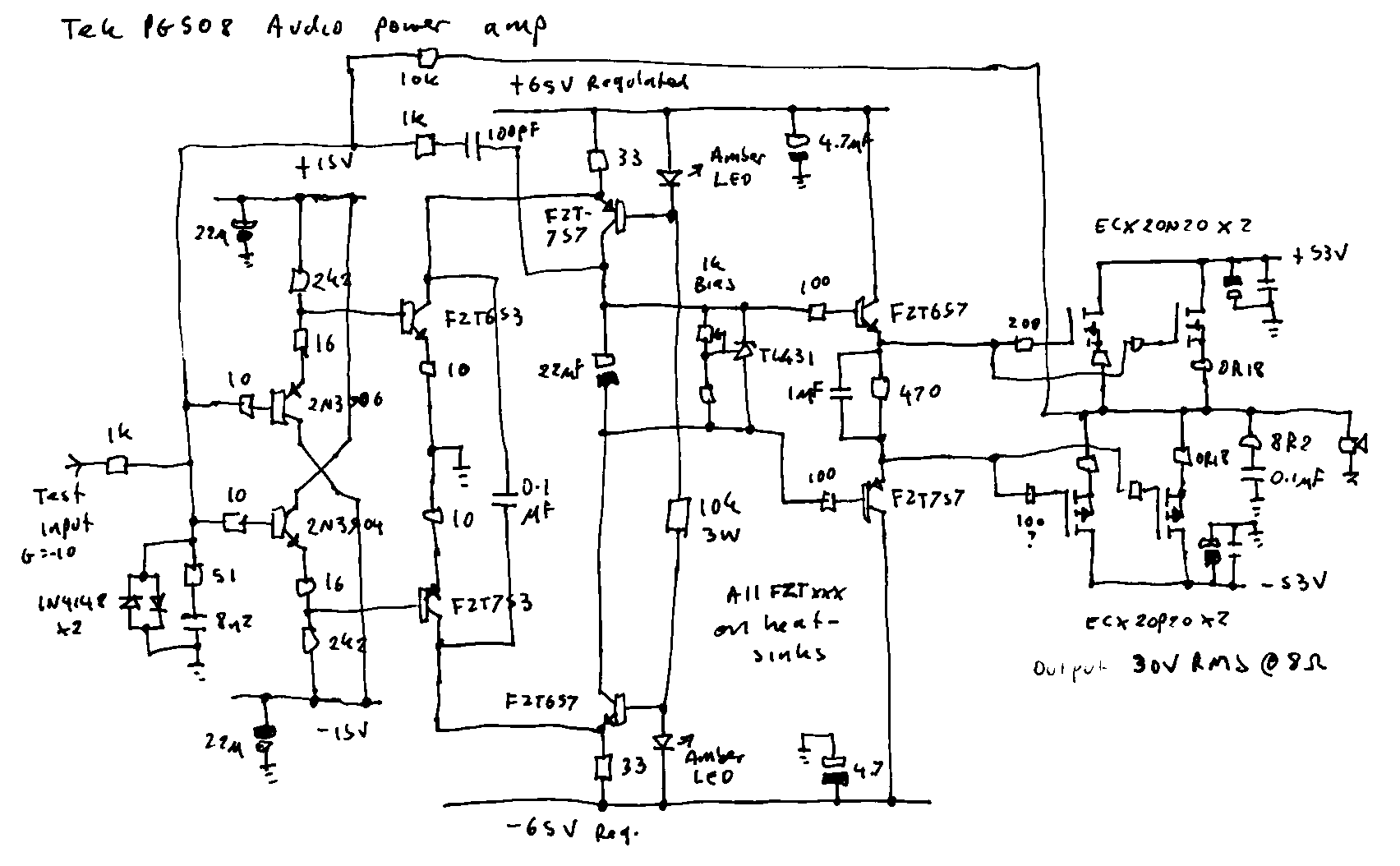
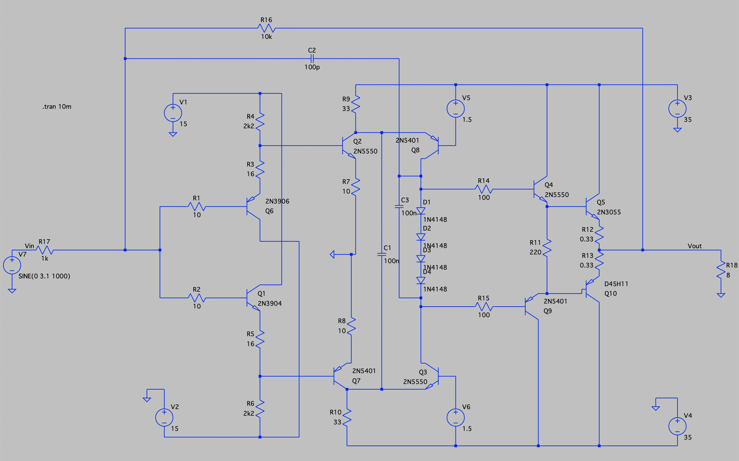
I was so excited (honestly 8) ) about the idea of a PG508-based audio amp that I decided to try building it in real life.
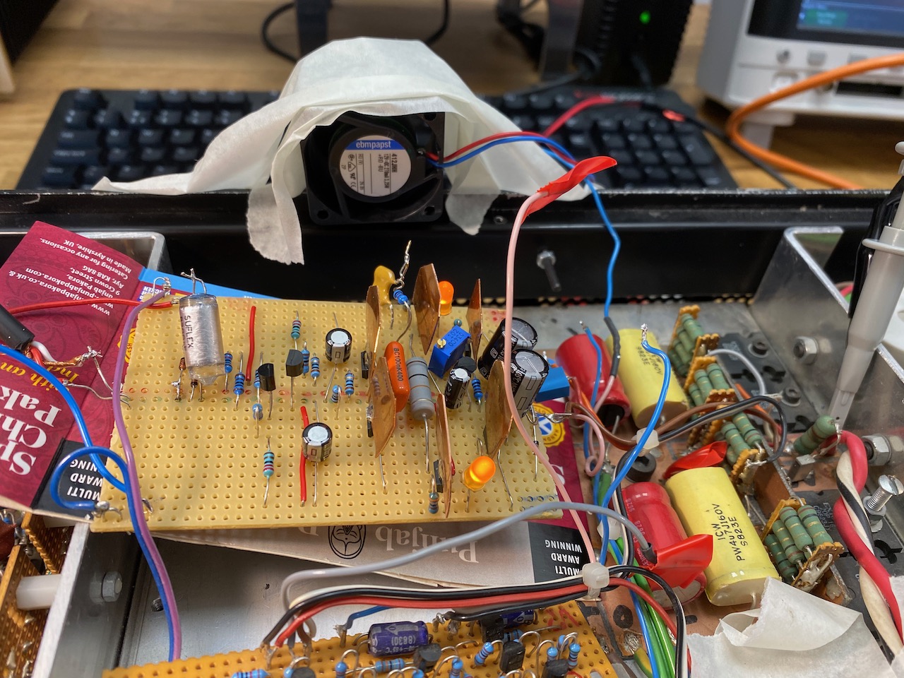
Fig.1: This is what I made
I first tested the driver circuit with +-15V supplies, no output stage and pure dominant pole compensation. It oscillated happily at 6MHz, and to get it stable I had to go back to the original PG508 lag compensation network (the 51 ohm and 8n2) The back-to-back diodes helped the clipping behaviour: without them you can reverse bias the cascode transistors and burn out the LEDs if you really overdrive it.
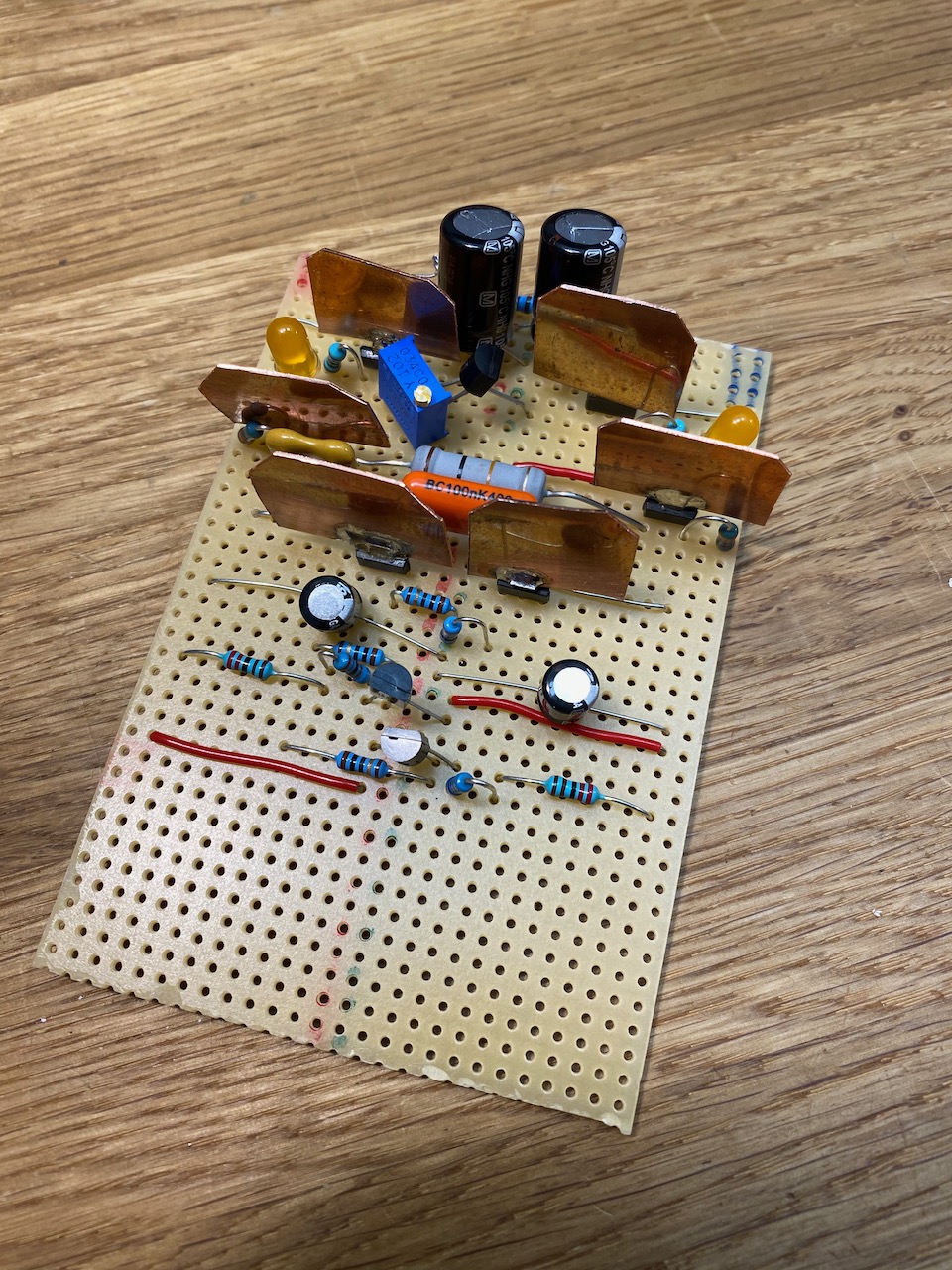
Fig.2: DIY heatsinks for SOT-223 transistors
In the interest of getting something working quickly, I hooked it up to the output stage and power supplies of my ancient and long-suffering Ice Block amp, which conveniently happened to be partly dismantled with one driver board missing. It provides regulated +-65V and +-15V rails in addition to the main +-53V, so no worries about PSRR for the time being.
Fig.3: The heatsinks weren’t quite big enough.
To achieve stability with the Ice Block’s hefty lateral MOSFET output stage in the loop (2 pairs of double die Exicon FETs) I had to use both the original PG508 compensation and dominant pole compensation with an extra zero (the 1k and 100pF).
I think it’s a bit temperamental because there are 3 transistor stages in the loop enclosed by the dominant pole capacitor. The Douglas Self Blameless only has 2, and my previous attempts at adding a third stage to that (cascode connection of Cdom) also caused oscillations at a few MHz.
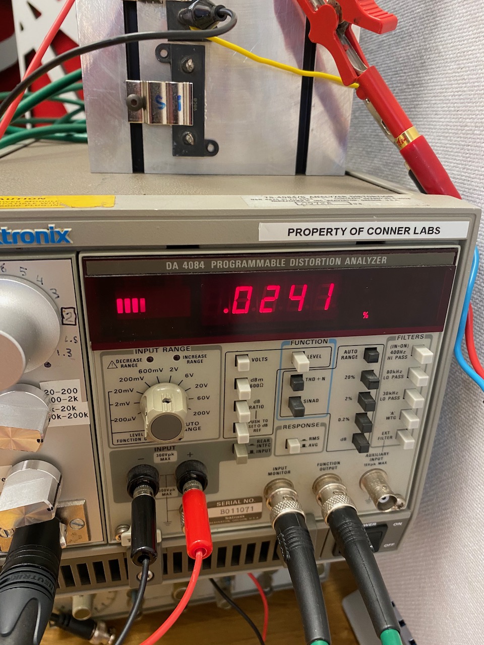
As with any half decent solid-state amp, THD+N was at the limit of my measurement system at 1kHz, and dominated by noise. I had to go to full power at 10kHz to see a meaningful distortion residual.
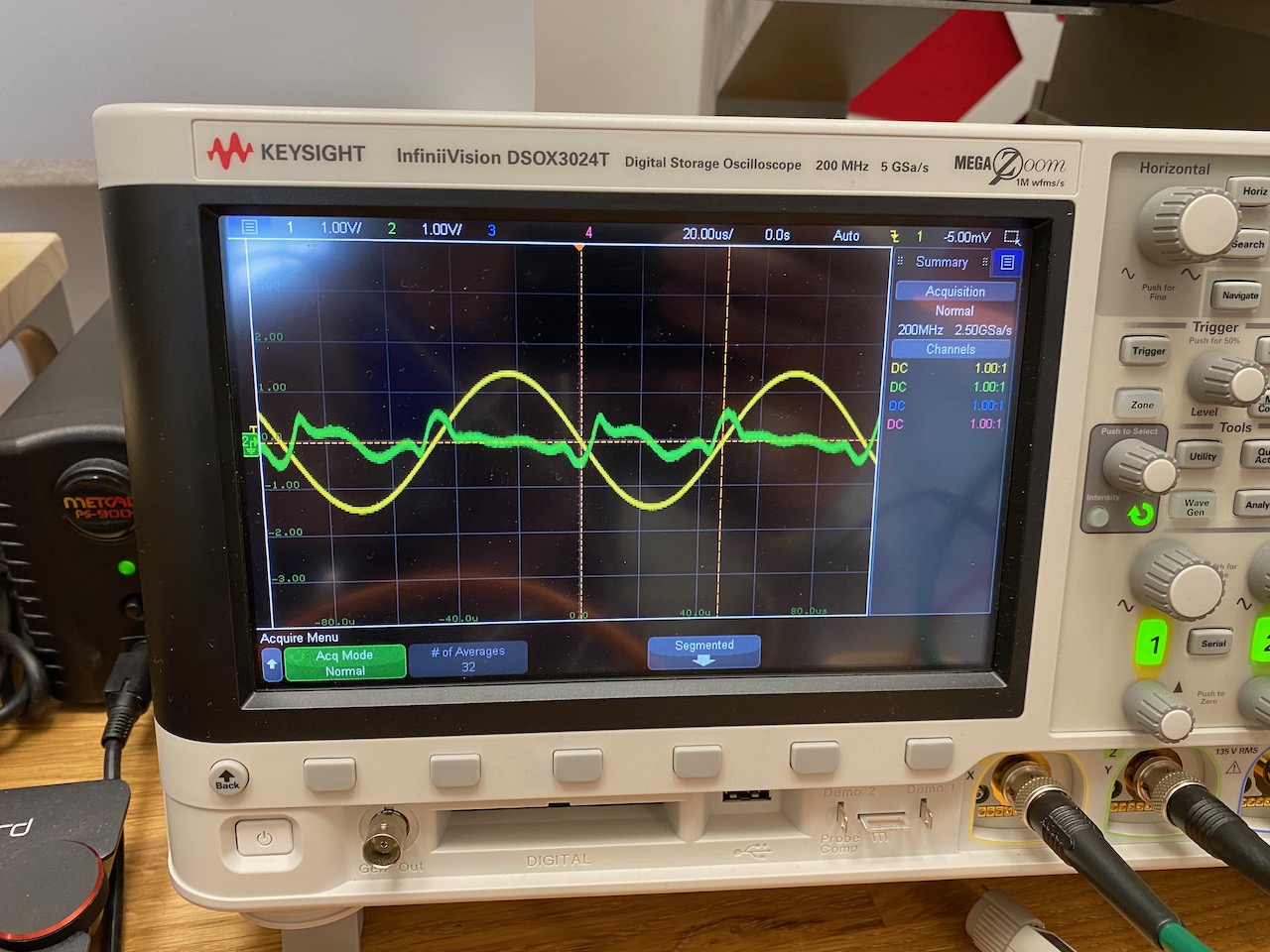
Fig.4: THD result at 10kHz, 100W into 9.4 ohmsFig.5: Distortion residual at 100W, 10kHz. (Fancy scope on loan from work 🙂 )
The distortion appears to be what Douglas Self called “gm-doubling”: in a push-pull circuit the gain is higher when both halves of the circuit are contributing, than when one half is cut off. And in the residual we see small lumps corresponding to increased gain around the zero crossings. I’m not entirely sure what part of the circuit is causing it. It may be the output stage, as that’s the usual culprit. It looks like it wants less bias, but the bias pot won’t go down any further. (Got to replace that TL431 with a TLV431)
I also tested the full power bandwidth, and it happily delivers 100W to 100kHz and beyond. I didn’t push it beyond 130kHz for fear of burning out the Zobel network.
A reading of 0.025% at 100W and 10kHz, with no filters engaged, is not to be sneezed at. I’d be perfectly happy with it, except the other un-hacked channel of the Ice Block does 0.009%! The PG508 circuit has some way to go before it can beat the original Alexander CFB.
While I had the equipment out, I also tried measuring distortion with a LF411 in place of the SSM2131 in the Alexander circuit. It made no noticeable difference at any power level, even though I’d persuaded myself that the LF411 sounded bad…
I recently came across this gem in the X Chapters supplement to the Art of Electronics 3rd edition. (Not reproducing here because of copyright. You need to buy the book anyway, it’s brilliant 😉 )
Fig. 1: Tek PG508 nifty folded cascode with audio power amp output stage duct taped on.
Of course my first idea was to convert it to dominant pole compensation (C2) and bodge a standard audio power amp output stage onto it.
This worked very nicely in simulation, so the next step was to slap on an opamp front end ala Quad 405 or Cordell Super Gain Clone.
Fig.2: opamp adds voltage gain and functions as DC servo
The resulting circuit should give a lot of bang for the buck when used with a good quality FET input opamp. I expect it to outperform the Alexander CFB design in areas that matter, like HF THD, PSRR, playing well with the standard Bailey current limiter circuit, and not depending on an obsolete opamp or catching fire when overdriven.
This is a voltage feedback design, not current feedback, and won’t beat the Alexander’s slew rate without running the transistors at crazy idle currents. Besides being CFB, the Alexander driver circuit operated in Class AB and could call on arbitrary amounts of current when slewing was required. The price it paid for this was catching fire when overdriven 🙂 and also crossover distortion generated in the opamp’s output stage, which is very audible if you use any other opamp than the original SSM2131. (And kind of audible even with the SSM2131 imo…)
So overall I am happy with this set of compromises and looking forward to trying it out in real life.
Regular readers will know that I’m a fan of Douglas Self’s Blameless philosophy of audio power amp design. (An uncontroversial choice, as the Blameless topology is not really that different to designs you would have seen in Wireless World in the 1970s, or indeed the innards of Bob Widlar’s opamps.)
Probably the biggest problem I have with the Blameless is the huge bias and offset currents at the inputs, which require a low resistance feedback network to avoid a huge DC offset at the output. This sets off a chain of design compromises and ultimately the carbuncle of C1 and D9 (Fig.1) pops up.
In my previous experiments I tried a matched pair for the input stage, but it made absolutely no difference. The collector currents aren’t necessarily matched, so neither will be the base currents. The biggest improvement was had by using high beta input transistors such as the now-obsolete BC213C. (MMBT5087 would be a suitable 21st century replacement.)
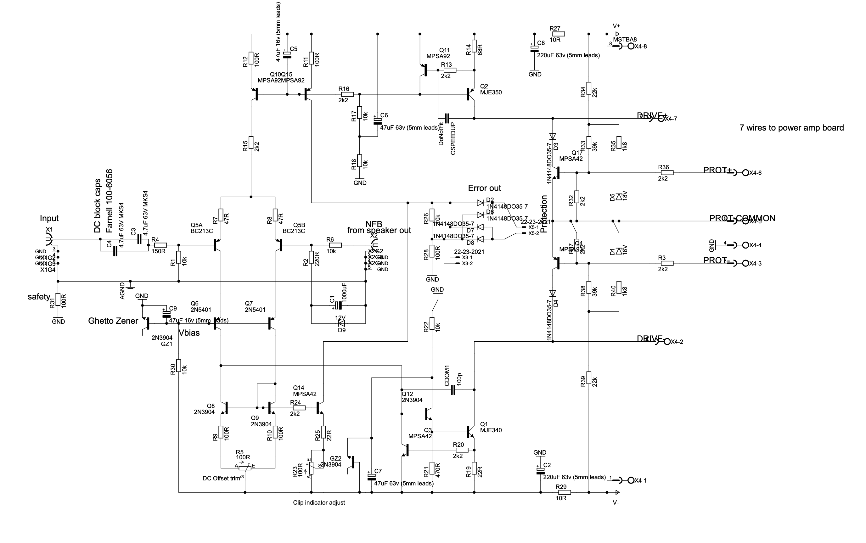
Fig.1: My original Blameless driver board
Revisiting this, I discovered that my first attempt at building it was badly unbalanced because of the clip detector (Q14 in fig 1) which robs a lot of base current from Q9. The other side of the mirror has Q12 robbing from it, but Q14 takes much more as it’s a high voltage part with low beta.
Fig.2: Improved version (complete model amp in LTSpice)
By adding a beta helper transistor to the input mirror (Q14 in fig 2) the imbalance due to base currents can be eliminated. The beta helper’s base current is drawn from one side of the mirror, and the base current of the Darlington VAS (Q2, Q17) comes from the other side. By setting R15=R7, Q2 and Q14 will run at the same collector current, so if they are matched for beta, their base currents will also be the same, and the whole input stage will be perfectly balanced to a first order.
(It’s not balanced to a second order because the current drawn from Q14 emitter by Q8-Q11 bases isn’t necessarily the same as that drawn from Q2 by Q17 base, but the imbalance due to this should be tiny. The clip detector can now be hung off Q8, Q9 bases with impunity. 2 transistors are now used to get a 2:1 ratio as required for balance with the current sourced by Q3. I used the same type of transistors as Q8, Q9 for improved balance, so a cascode Q23 is now needed because of their limited voltage rating.)
The other side of the problem was limited beta in the input stage. One of the pillars of the Blameless philosophy is to run the input stage at a high current to give it lots of gm, which you then throw away with emitter resistors. The goal is good slew rate, and the price paid is the high input bias currents.
We attacked the input offset current issue by improving balance of the collector currents (and hence base currents) but if we could reduce the input bias current too, the offset current would decrease still further in proportion.
A promising approach seemed to be replacing the input transistors for Sziklai pairs. (Q6, Q15, and Q7, Q16 in Fig 2.) Now the actual input transistor Q6 can run at a low current (300uA in this case) while Q15 conducts the remainder of the high current needed for decent slew rate. We have a double win because the Sziklai pair is more linear than a plain transistor.
Adding more and more transistors inside a feedback loop is always dodgy, and running one of them at low current where its Ft will be reduced especially so. In this case though, I think the bandwidth will still be adequate. The whole mess is cascoded by Q12, Q13, so there will be no Miller effect to slow Q6, Q7 down. The degeneration from R5, R6 should also help to stabilise things.
The LTSpice simulation of this showed an overall DC offset of 20uV, a huge improvement on my previous Blameless driver board. Of course this is with perfectly matched virtual transistors, but I think the real thing will do pretty well when built with BCM846/856 matched pairs. They specify Vbe to be matched within 1mV, and (what really matters for this circuit) beta to be matched within 10%, which works out at a 100nA worst case input offset current.
The overall result is that the DC offset and clip indicator trims from my original design can be done away with, and the impedances in the input and feedback networks can be increased by a factor of 10, for the same worst case DC offset of about 10mV at the speaker terminals. This means that C1 the obnoxious 1000uF electrolytic can be replaced by something more audiophile grade: the same 10uF plastic film capacitor that used to be the input DC block.
This is what the simulation says, so now I have to build one and see if it works in real life… 🙂
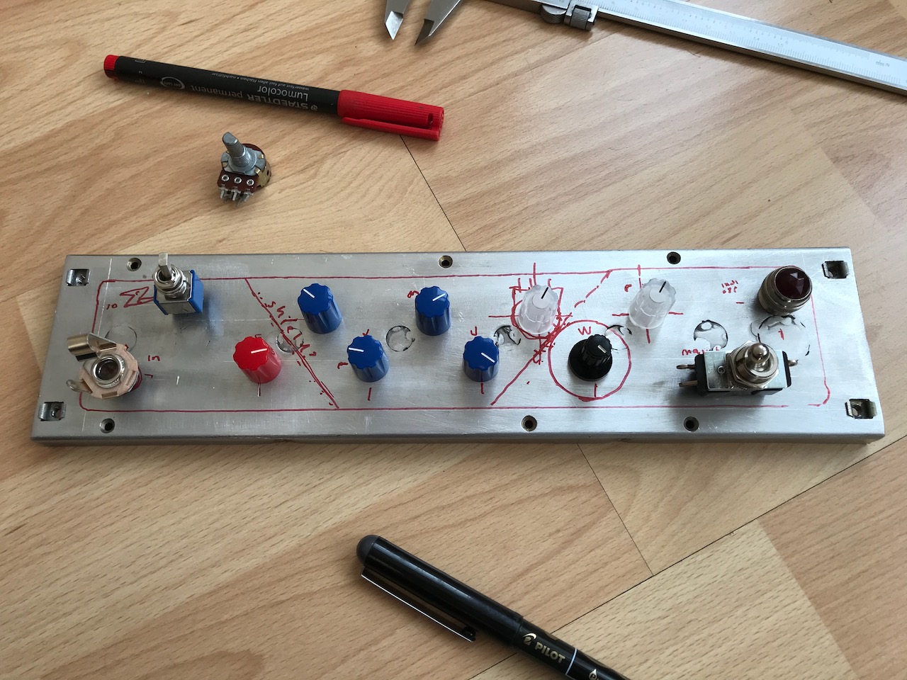
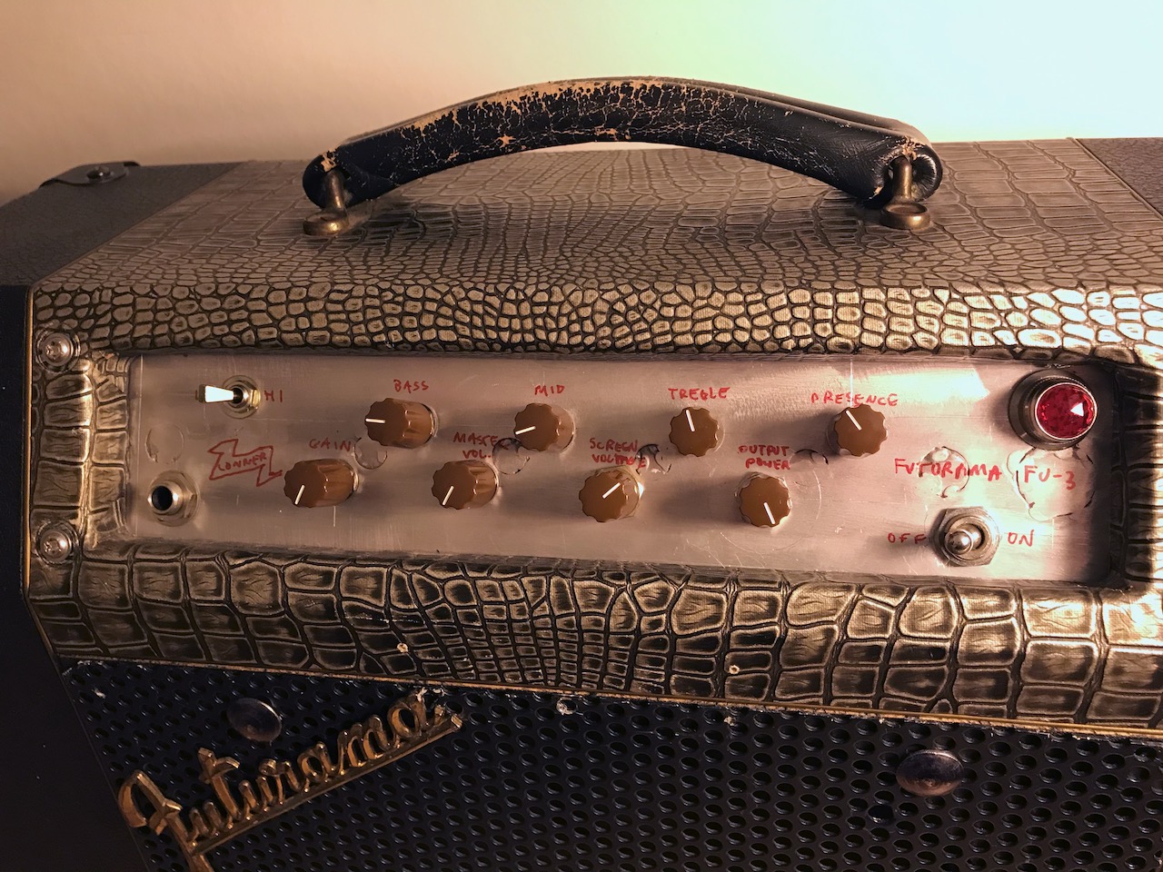
For more aluminium welding practice I decided to weld up the knob holes in the original Corvette front panel. The front looks OK but you don’t want to see the other side. I then made a new layout using MAD- permanent Marker Aided Design.
Next step was to finish wiring up the Marshall 2204 preamp.
See earlier posts on the Ninja Corvette Hybrid if you’re puzzled by all the extra transistor stuff.
Yeah it makes the master volume Marshall racket 😀 This was recorded at the 1W power output setting.
Got some matching knobs from Thonk. I will get round to making a completely new panel one day using the MAD one as a template.