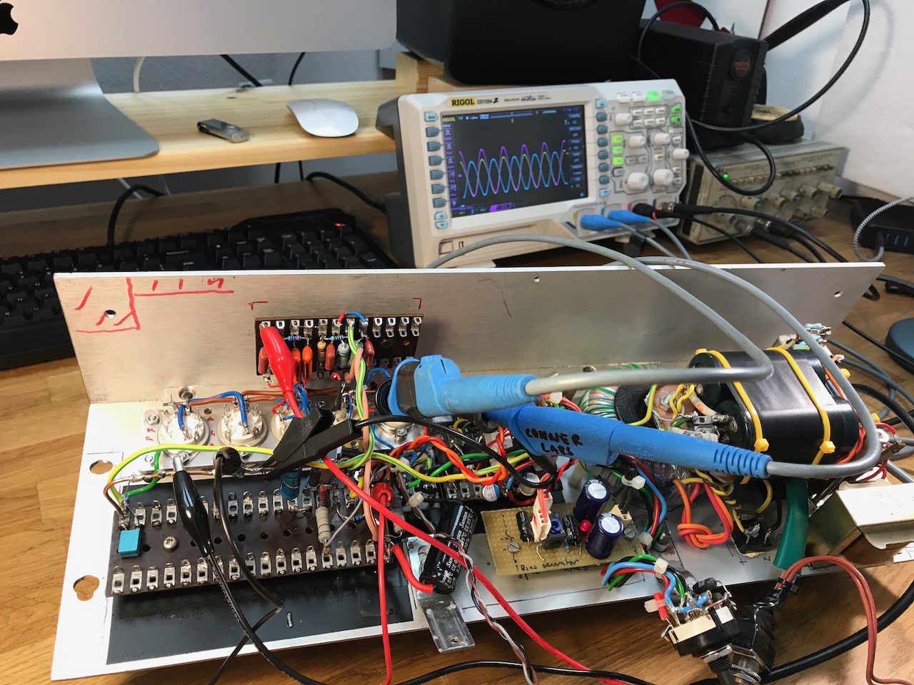
Soon the phase inverter and power amp were finished and working.
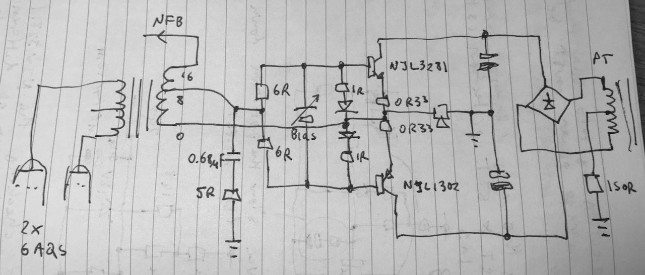
One big difference is that the 2204 uses negative feedback around the output stage while the original Corvette didn’t. So I decided to go with the NFB, and include the transistor output stage in the feedback loop too for an extra challenge.
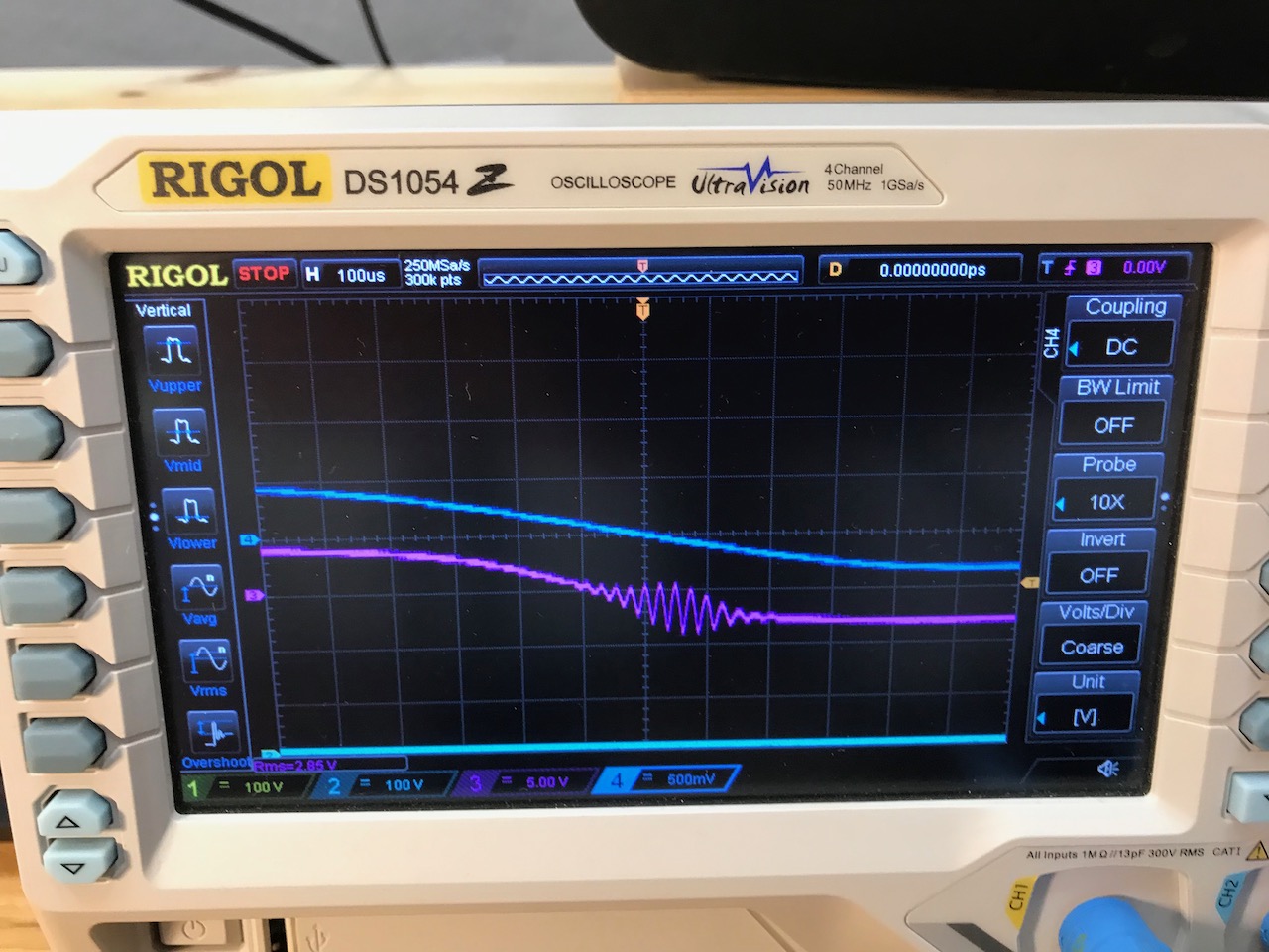
It was perfectly stable first time! LOL just kidding… It suffered from high frequency parasitics-
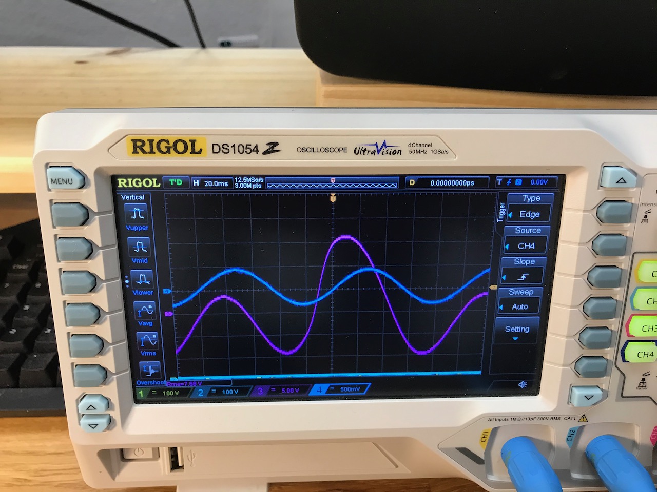
And these comically chaotic LF oscillations could be provoked by overdriving it at low frequencies.
After much trial and error I ended up with something like this. The 0.68uF/5 ohm RC snubber killed the HF oscillations, and removing C17 and C18 (this schematic) stopped the motorboating. With these values it was just barely stable with the load disconnected and a 220k NFB resistor (vs 100k in the original 2203 circuit)
Note that when the transistor output stage is in play, the OPT secondary becomes bootstrapped and flies around with the speaker output, so the NFB takeoff point I used sees the output voltage of the transistor stage plus the output voltage of the valve OPT.
Removing C17 and C18 demanded quite a lot of extra current from the bias generator, but it seemed to deliver it no problem, so no changes were required there.
Resistor values were also changed to reduce the current gain of the transistor output stage, due to the increased output of the valve part of the circuit.
I got bored of the Ninja Corvette Hybrid and decided to transform it into something with a little more “FU”.
The plan I came up with was to strip out the valve part of the circuit and replace it with a clone of a Marshall 2204. This is a classic rock amp that I hadn’t had much experience with.
I decided to use 6AQ5 power tubes running off 250V, for a modest apartment-friendly power output. The 3 position power switching would be retained, giving power levels of 1W, 10W and 40W.
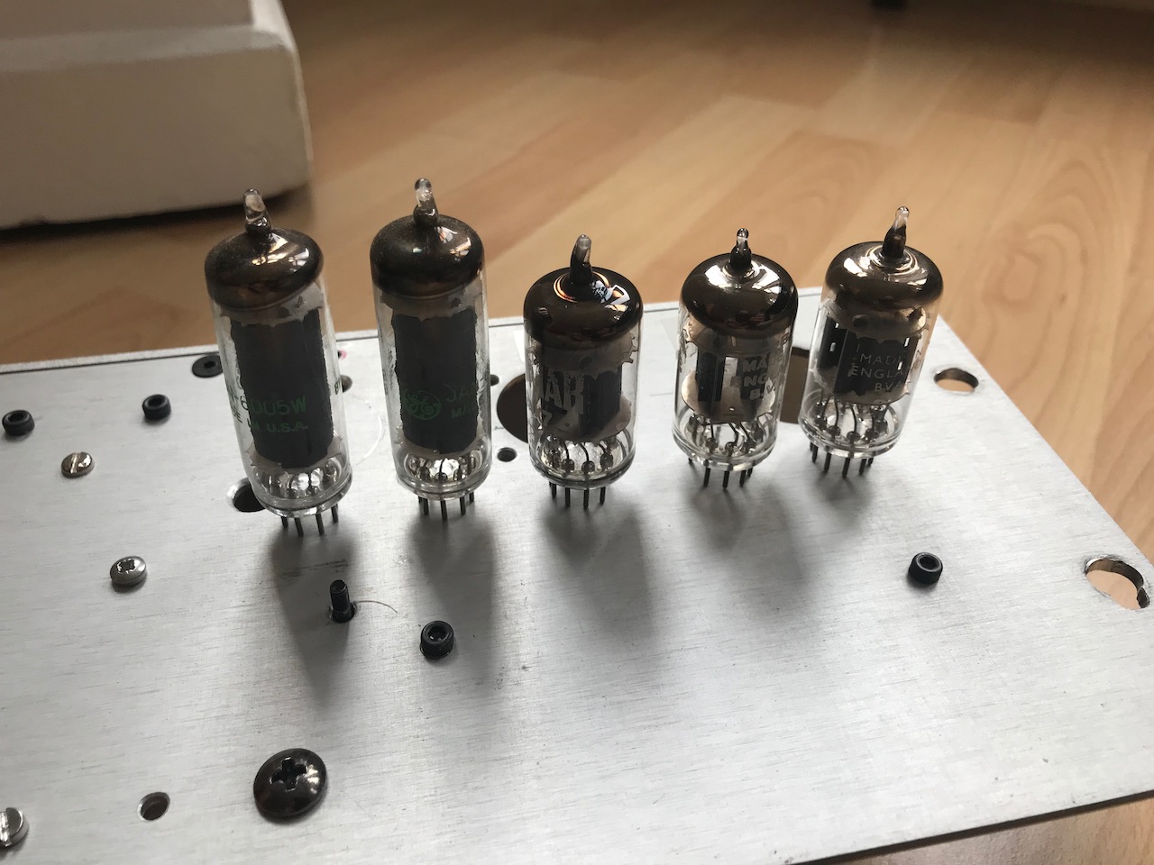
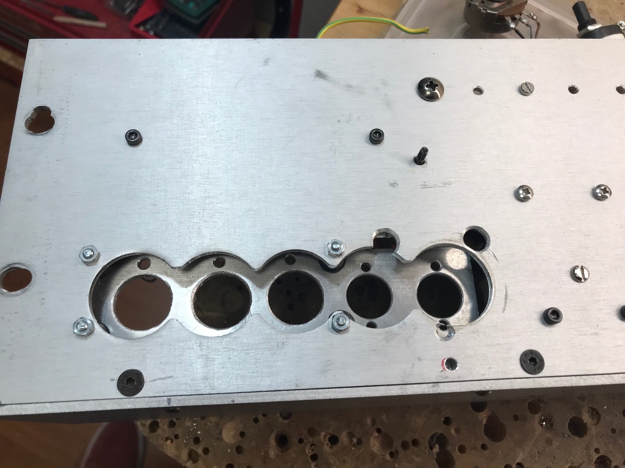
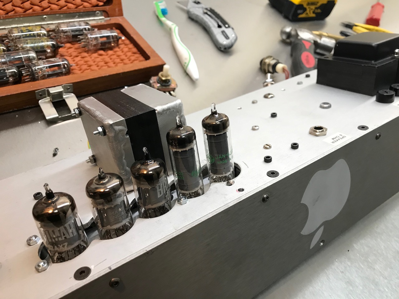
The Marshall 2204 circuit has 5 valves, but there are only 2 holes in the chassis…
A new output transformer was also required, as the original one was single-ended. I used the cheapest PP one I could find at TAD. I also TIG welded a bracket for it, as I’ve been watching way too much Project Binky.
It was time to put it all together! (This actually happened in March- these are post hoc posts 🙂 )
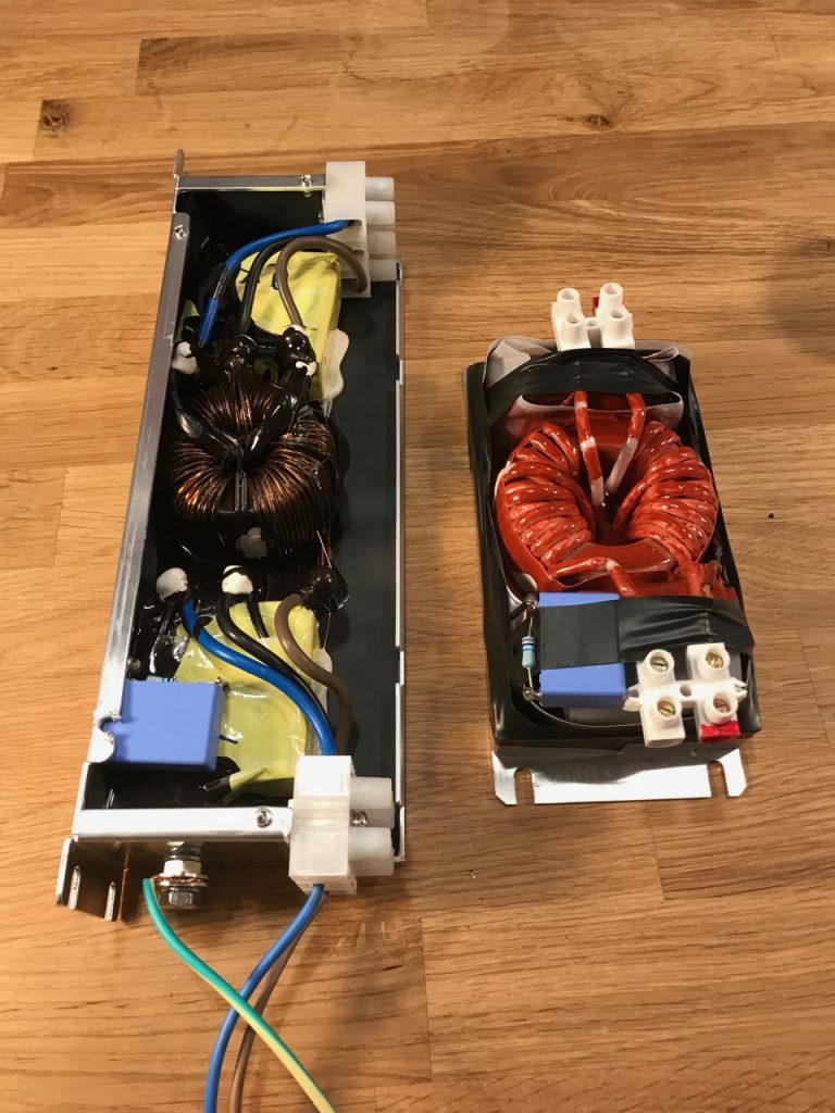
Tesla coil driver converted for 24V DC control power.
First Odin’s control electronics had to be converted to run off 24V DC instead of the original 240V AC. (And mounted in a Eurorack while I was at it…) This wasn’t too difficult as they already used 20-something volts DC internally, derived from the mains with a traditional iron cored transformer and rectifier, and regulated to 15V.
24V DC input module. It is essential to test this on a furry rug.
I added DC input sockets to the driver and gate drive amplifier modules, and changed the fan for a 24V one too. The original 240V AC inputs are retained in case the PFC breaks down and I need to change back to the old power supply.
The PFC will be situated at the operator’s position with long cables for 750V and 24V running to the coil. This made everything simpler, as there was no need for remote control and the circuit breaker on the PFC could be the emergency shutoff for the whole system. But it did leave the 24V cable vulnerable to strikes and general pickup of the extreme levels of EMI around a Tesla coil. My solution was to make a DC input module using a surplus Traco 40W DC-DC converter to give galvanic isolation, and lots of EMI filtering on both input and output.
The red module is the receiver for my Teslink system that sends multiplexed control signals over a Toslink optical fibre. I finally got round to completing it (and making a Eurorack mounting transmitter too)
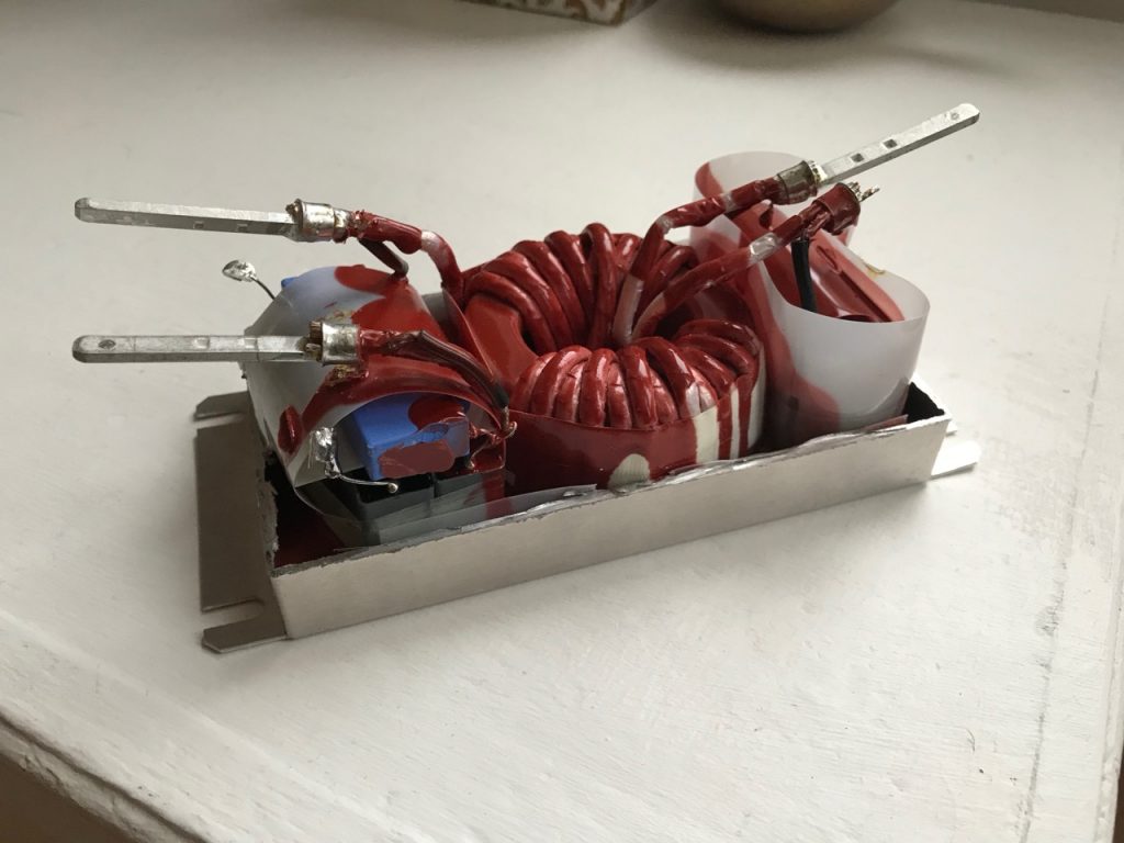
PFC provides 750V DC output (on left) and 24V DC (on right)
The idea is that the PFC accepts single or 3 phase power at anywhere between 208 and 415V, and supplies 24V DC to the Tesla coil electronics from its own control power supply. I didn’t want the hassle of having to change taps on control power transformers, or rather the carnage of connecting it to 415V with the taps set to 240. (I have done this before- it was messy)
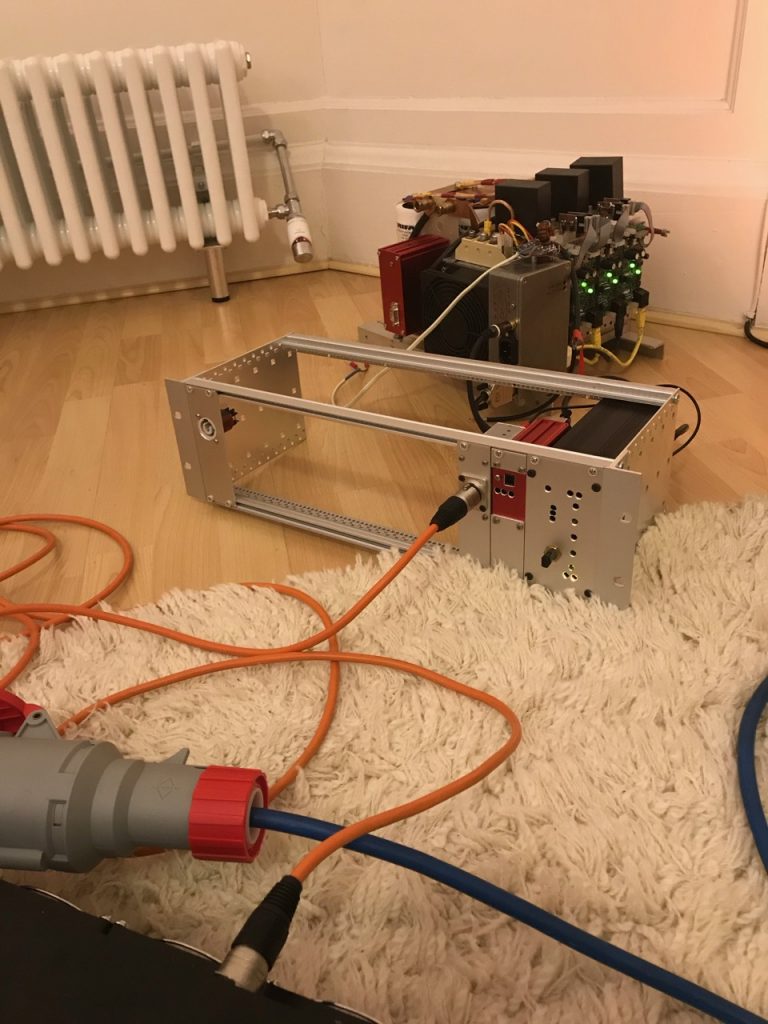
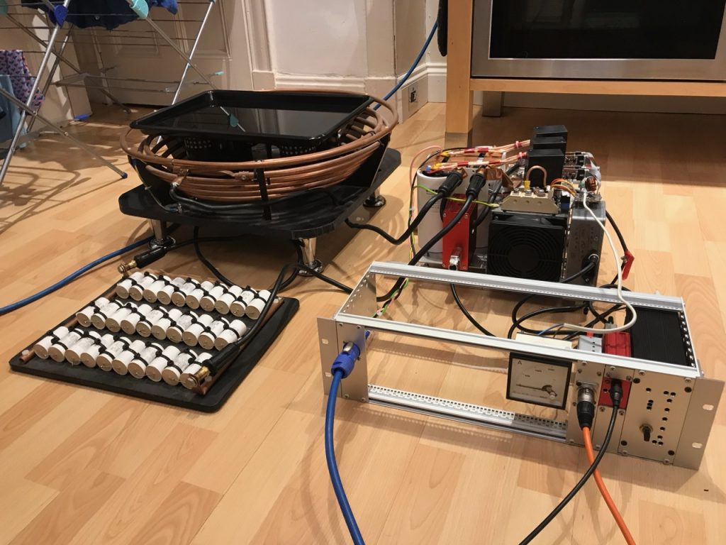
Setup for integration test
The Tesla coil primary was set up using a water-filled steel pan as a dummy load.
It didn’t explode! 😀
The next step would have been to take the PFC and immersion heater bucket to a lab with 3 phase 415V power. Unfortunately this was made impossible by the COVID-19 lockdown. The debut was to have been the Nottingham Gaussfest, but this was also cancelled. Insert corona joke here 🙁
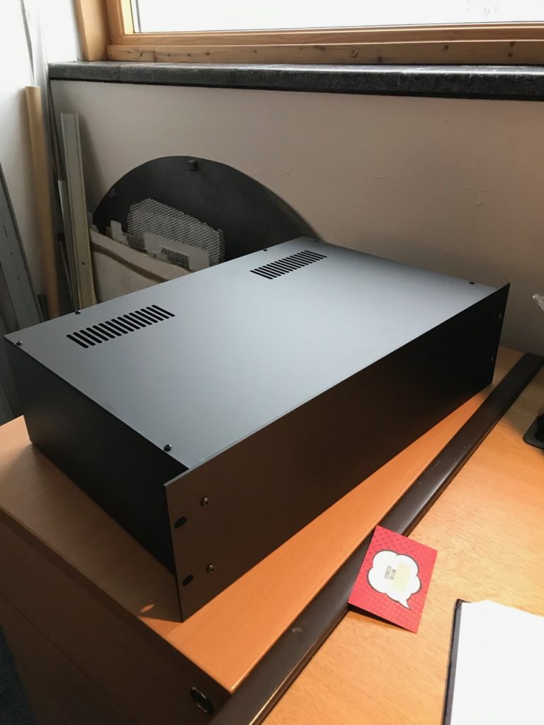
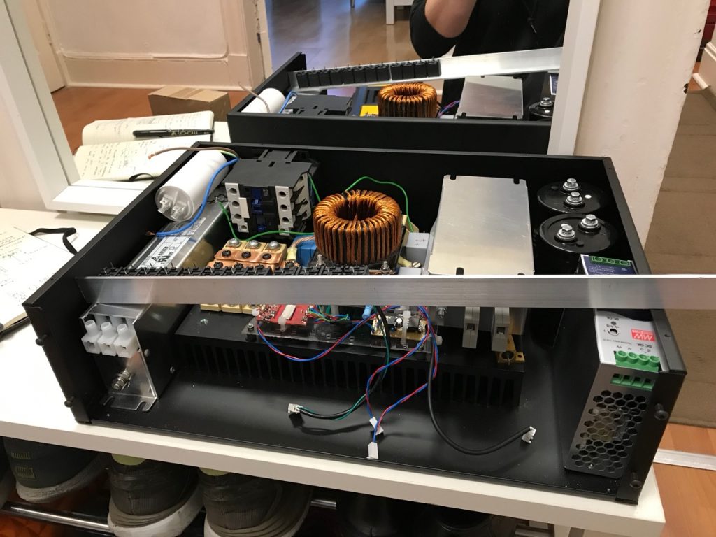
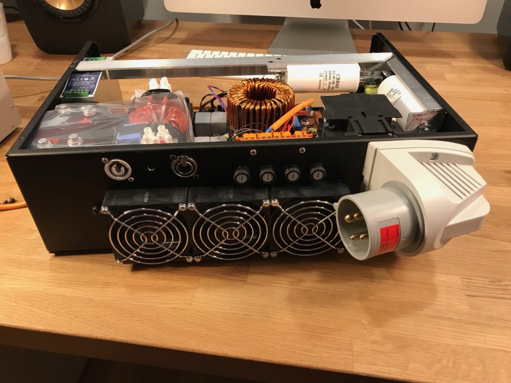
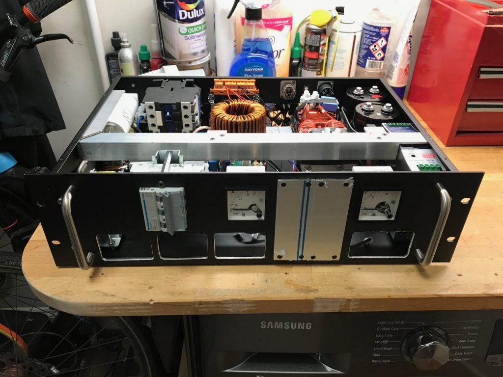
Penn Elcom rack enclosureTrial fitment of componentsIs this what they mean by a multi-level converter?Trial fitment 2Bleed and ballast resistors attached to heatsinkTrial fitment 3 with EMI filtersRear panelMetalwork nearly finishedTesting the precharge circuitAnd it’s done
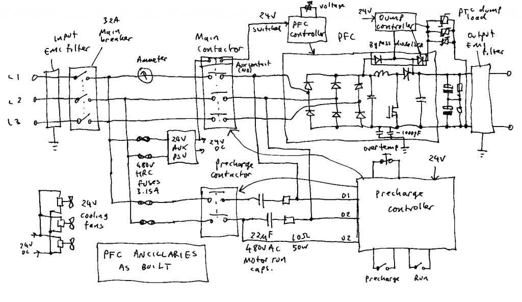
Before I could get on with building the PFC into an enclosure, I had one last design decision to make: What sort of EMI filtering to use. The size and shape of the EMI filters would affect the rest of the mechanical design. Ok, that’s management speak for “How am I going to get all this cr@p into the 3U rack enclosure I’ve already purchased?”
Now, I deal with EMC in my day job and am vaguely familiar with the standards and test procedures, but this is a one-off handmade power supply for a Tesla coil. It’s never going to get tested for emissions, and the emissions from the Tesla coil will dwarf the contribution from the power supply anyway.
So the main purpose of the EMI filters is to protect the PFC from malfunction or damage caused by the Tesla coil emissions. These tend to be common mode transients caused by ground strikes, containing frequencies up to the 10s of MHz. There isn’t a great deal of VHF or UHF energy due to the length of the spark channel. So they really aren’t super hard to filter out.
I prefer to connect the filters so the Y capacitors (jargon term for the capacitance between lines and ground) are at the end connected to the outside world. My reasoning is that I’d rather any incoming transients were dumped to chassis ground through the capacitors, than potentially flashing over a choke.
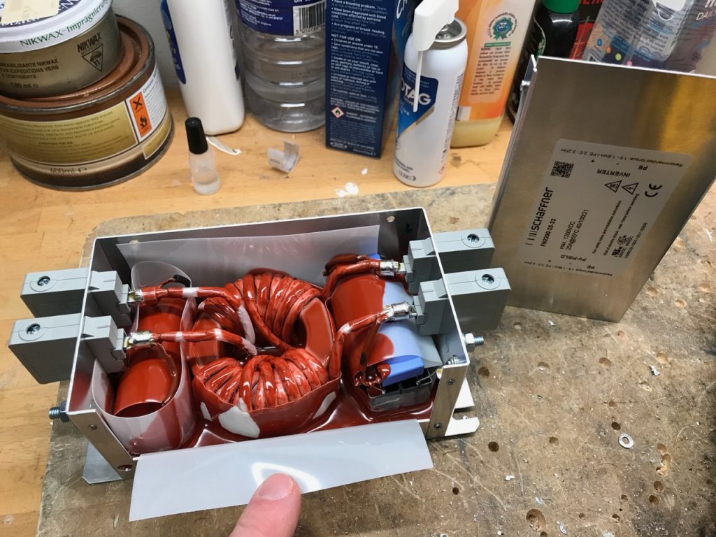
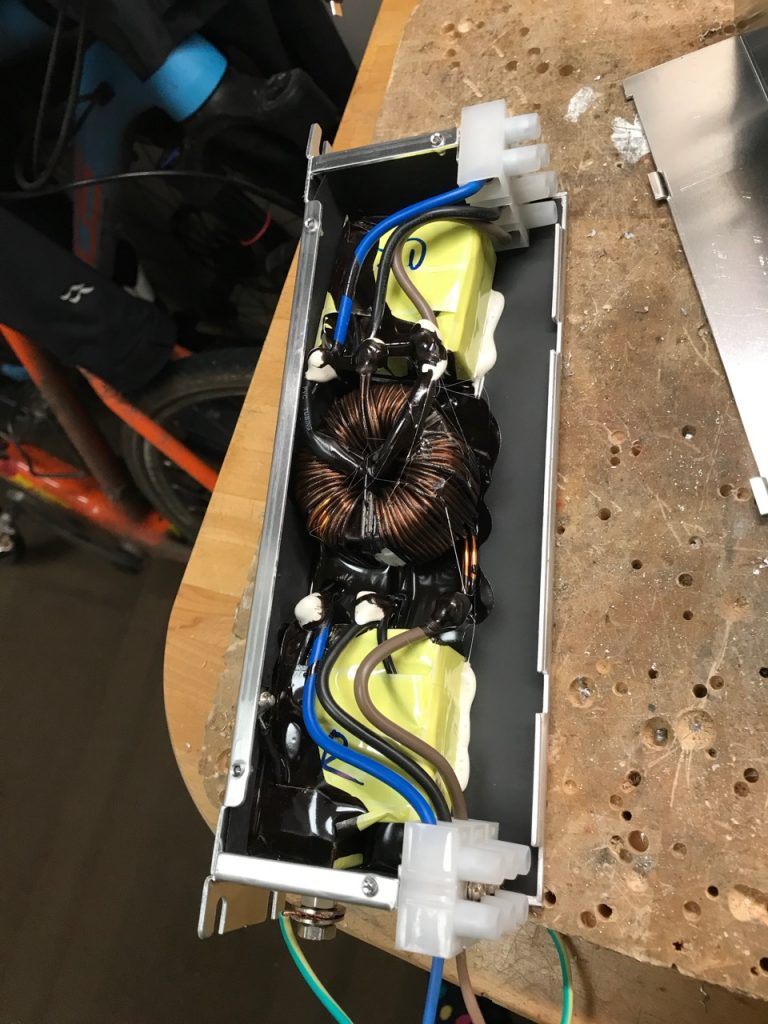
I started by trawling the RS, Farnell and Mouser catalogues for ready-made EMI filters. I ended up with a Delta 30TDVST2 for the input and a Schaffner FN2200-25-33 for the output. These both had the Y capacitors at the load end, so would have to be used backwards from the maker’s recommendation.
I soon discovered a serious problem with both filters: a very high Y capacitance. This isn’t a problem in the intended industrial application, but a bit of a show-stopper for mine. When the PFC is used on a single phase supply, the high capacitance causes enough earth leakage current to trip any RCD. Note that the Y capacitance of the DC output filter also contributes to the leakage, because the DC output is not isolated from the mains and has AC superimposed on it.
I couldn’t find any better filters, so I broke them open and set about reducing the Y capacitance.
Schaffner used stainless rivets that were a pain to drill out, but I got there.The innards of the Delta. Not super impressed with build quality.Schaffner FN2200 gets a careful trim with the angle grinder.The modified filters
I lifted the connection between Y capacitors and earth, and added a 68nF capacitor in series, with a 2.2M discharge resistor. This should give a total leakage current budget of around 10mA at 240V AC. (Odin has 2 68nF capacitors from DC bus to ground already, which contribute too)
The modified filters no longer tripped my house RCDs, so the job was done. In hindsight, I wouldn’t buy ready-made filters again. It would have been cheaper to buy the parts and make them.
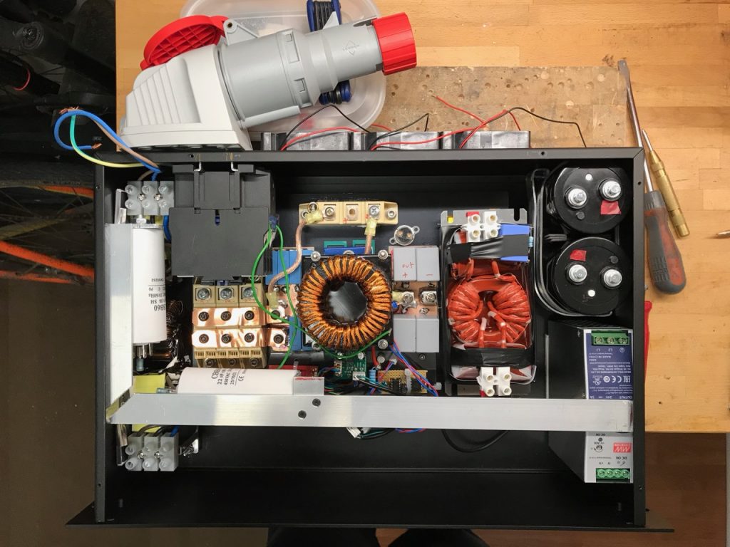
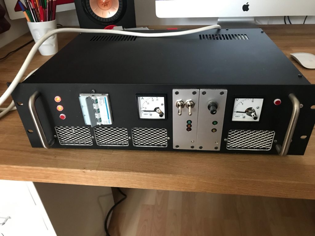
The PFC engine is working, but there are a few other things needed to make it usable. (Operationalise it? Or Heaven forbid, weaponise it? 🙂 )
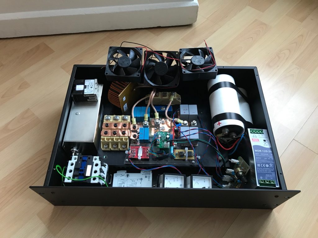
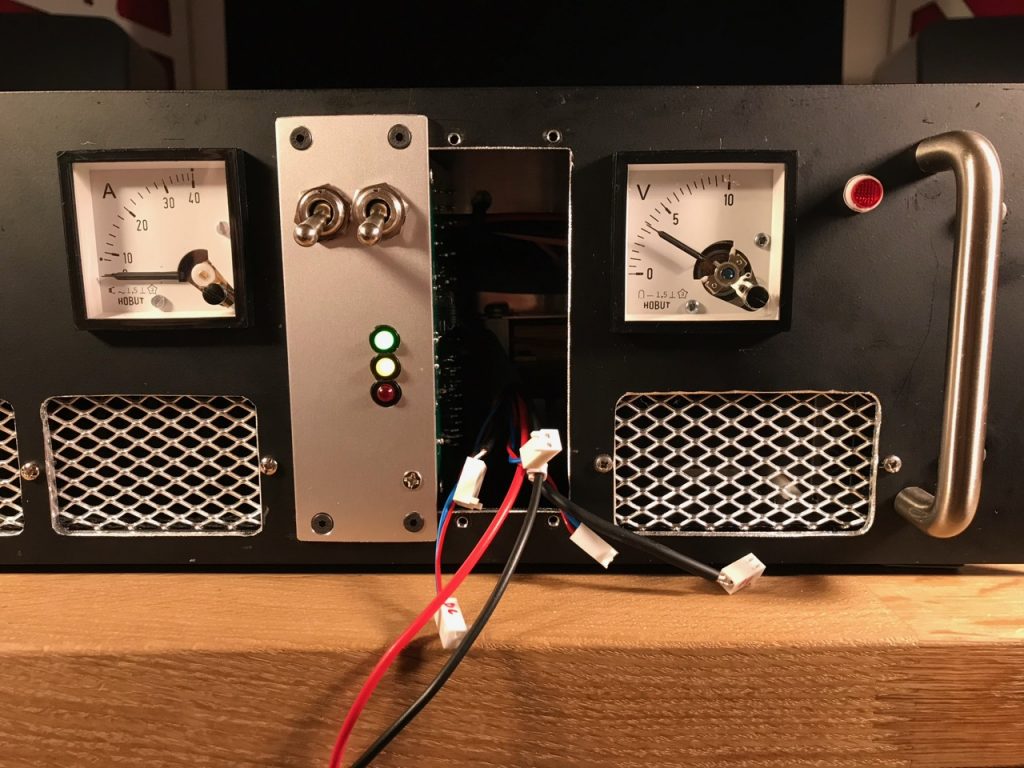
The other stuff as built. (Except the output voltmeter which I forgot)
Auxiliary power supply: The PFC needs a small amount of power to run its own control electronics. I decided to use a Meanwell WDR-120-24 switching power supply to provide 24V DC. This is an industrial grade unit that will accept any input voltage from 200 to 500V AC.
The WDR-120-24 is a bit more expensive than the usual 85-265V input range units, but vital for my goal of being able to run the PFC off either 230V single phase or 400V 3 phase power, without any kind of voltage selector switch that could cause carnage if set wrongly.
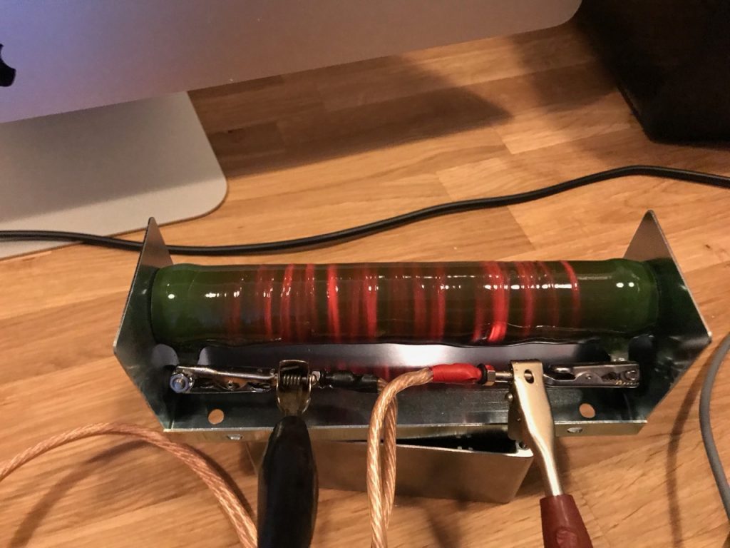
Precharge: The bus capacitance of the DRSSTC is very substantial. Odin has 4700uF after a recent upgrade. The PFC itself will also need another 1000uF to allow it to work without the DRSSTC connected. All of this has to be charged to the peak value of the mains voltage before the PFC can even start, in an orderly manner without tripping any breakers.
I chose a capacitive ballast for this job, consisting of 22uF motor run capacitors with 10 ohm resistors in series. The capacitors do most of the current limiting while the resistors protect the capacitors and main contactor from the surge when the capacitors are shorted out. The resistors are attached to the main heatsink and protected by the overtemperature cutout.
The precharge controller is based around a time delay and voltage sensing relay. (Schematic in a future post) The voltage between D1 and D2 must get over 200V, and the voltage between D2 and U2 below about 20V, before the sensing relay will pull in. This energises the main contactor, connecting the PFC input rectifier directly to the mains, and powering up the PFC controller through its auxiliary contact. The PFC then goes through its own soft start procedure, charging the DC bus capacitance to full voltage.
Dump load: The large DC bus capacitance also needs discharged when the system is powered down. My previous coils all relied on bleed resistors and took over a minute to discharge. For this build I decided to try some PTC thermistors from Epcos. (Details in a future post.)
The main advantage of PTCs is that, unlike normal resistors, they limit their own temperature and won’t catch fire or explode if the switch controlling them accidentally turns on while the DC bus is powered. This allows me to switch them with a SCR which was already present in the bypass diode module.
EMI filtering: This is as much to protect the PFC from damage by the huge transients generated by the Tesla coil, as to protect the mains from the hash thrown out by the PFC. My search for suitable off-the-shelf EMI filters is documented in another post.
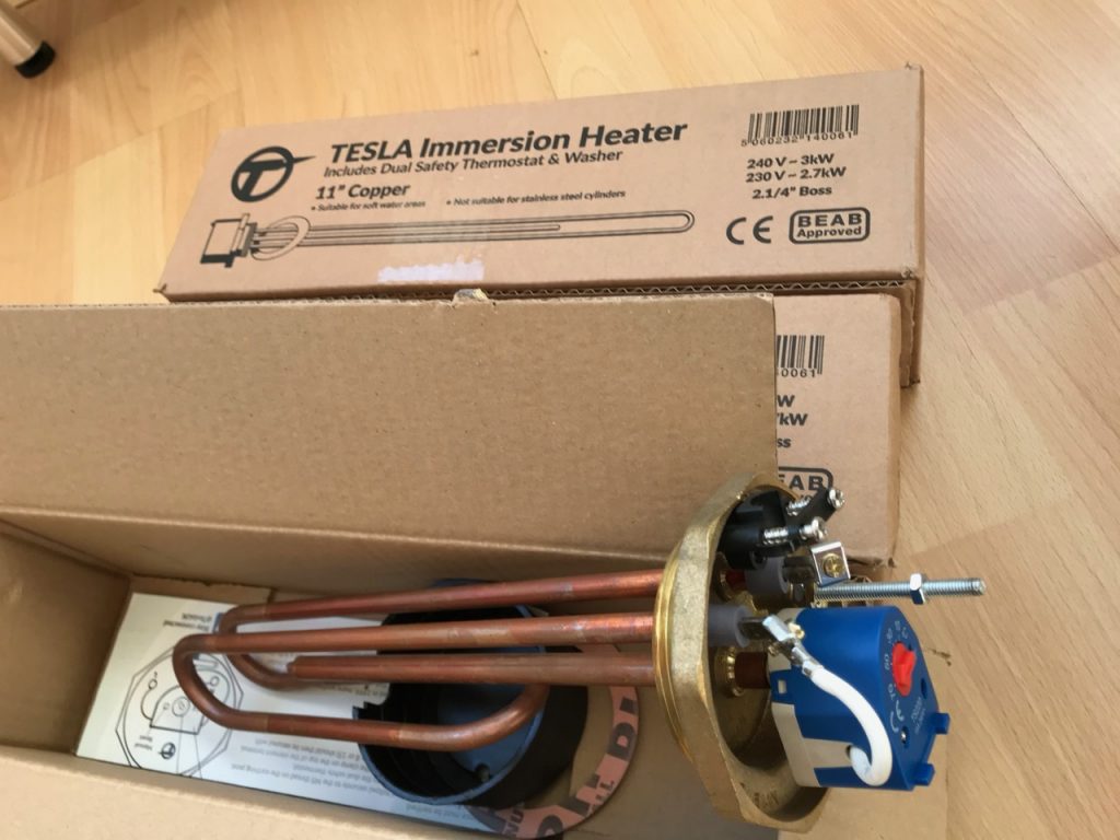
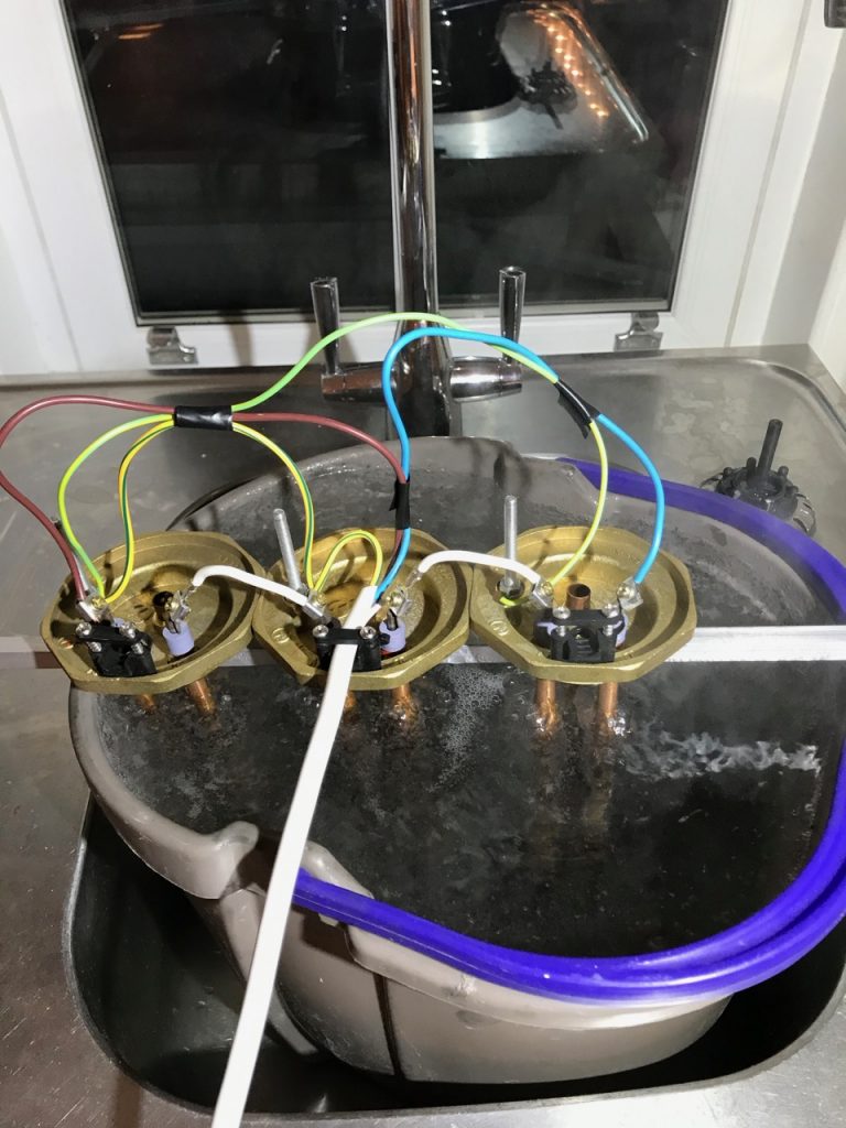
The low power test was a success, so a larger dummy load was obtained- 3x 240V, 3kW water heaters connected in series.
They’re even Tesla branded! 8)
The PFC was placed on a special tea tray test fixture and temporarily wired into the electric cooker supply in the kitchen.
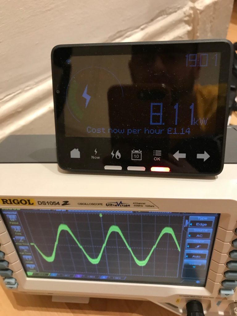
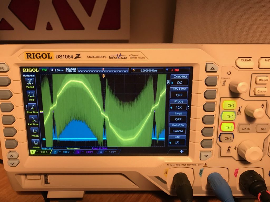
According to my smart meter the result was 8.1kW input, though the other house appliances were using a few hundred watts at this point. The line current waveform looked nice. I used an EMI filter this time so the garbage at the switching frequency is reduced.
The moment of truth could be put off no longer 🙂 The PFC was tested at reduced input voltage using a 110V, 100 watt heater as a load.
Complete assembly. Note bunch of extra electrolytic capacitors on output.Line current waveform looks reasonable. (Using a Fluke current clamp)Maybe a bit more than 100 watts?
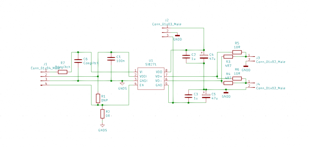
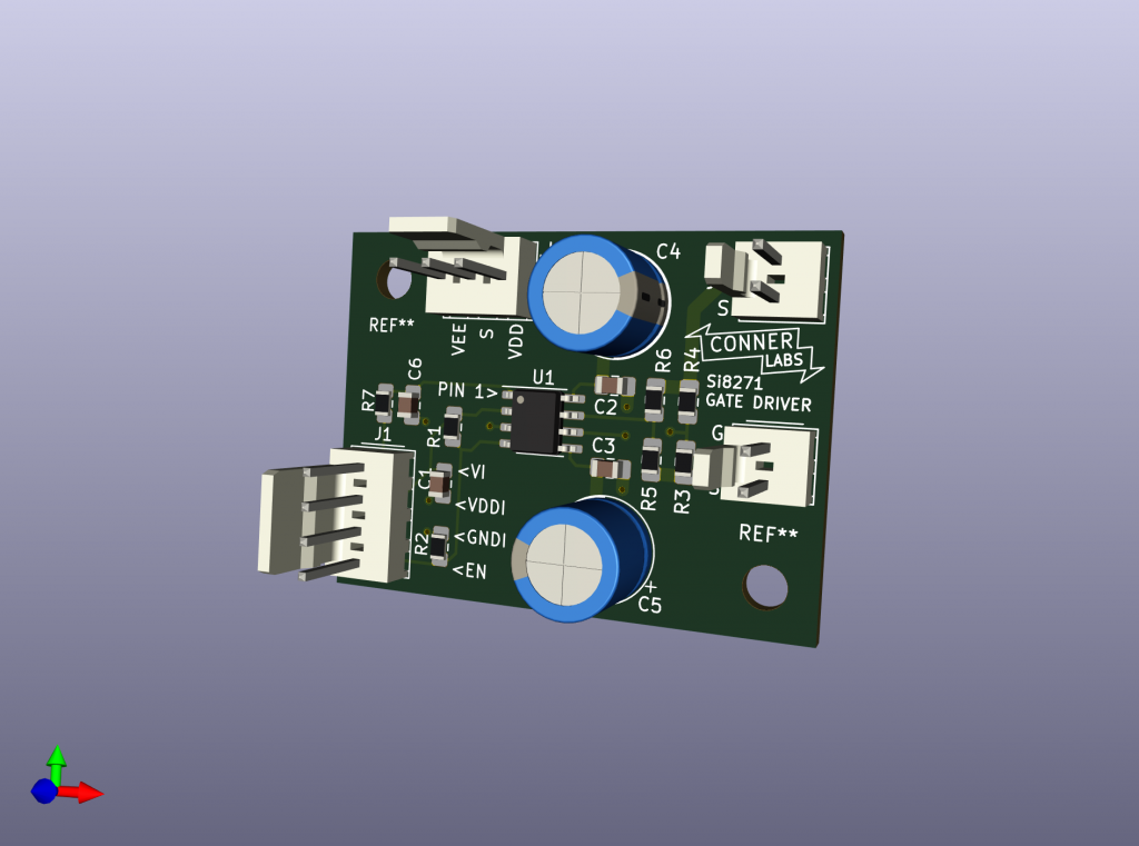
In the previous post I mentioned that I couldn’t drive the MOSFETs directly from the controller chip because they need a negative voltage to turn off. The easiest way to provide this was with an isolated gate driver using the excellent Silicon Labs Si8271 IC.
Due to the tiny size of this IC and the requirement for a very tight layout to minimise stray inductance, I designed a PCB for it. This was also an excuse to finally start learning Kicad after years of using Eagle.
Schematic
Power is supplied by a Murata MGJ6 DC-DC converter connected to J2. +15V to pin 1 and -5V to pin 2. The same DC-DC converter powers the opamp on the voltage feedback isolator board.
R7 is a small value like 22 ohms. I installed a 10k resistor in place of C6 to pull down the input if it became disconnected. R2 was not fitted and R1 was a 0 ohm link, the opposite of the schematic (I got the enable pin logic the wrong way round)
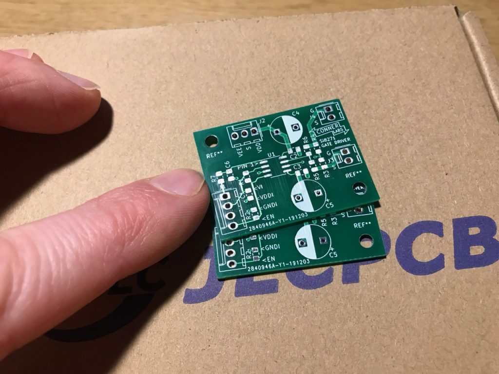
Kicad’s glamorous 3D PCB viewer
I uploaded the Gerber files to JLC– a Chinese manufacturer based in Shenzhen who ship worldwide- and had the boards the following week for a cost of about £5. JLC are 1/10 the cost of any UK PCB house and have really lowered the barrier to entry for hobbyists.
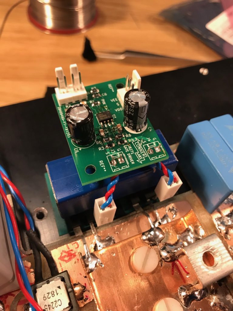
I even got a free ballpoint pen! (Not shown)Installed and connected to the MOSFET gate and source terminals.
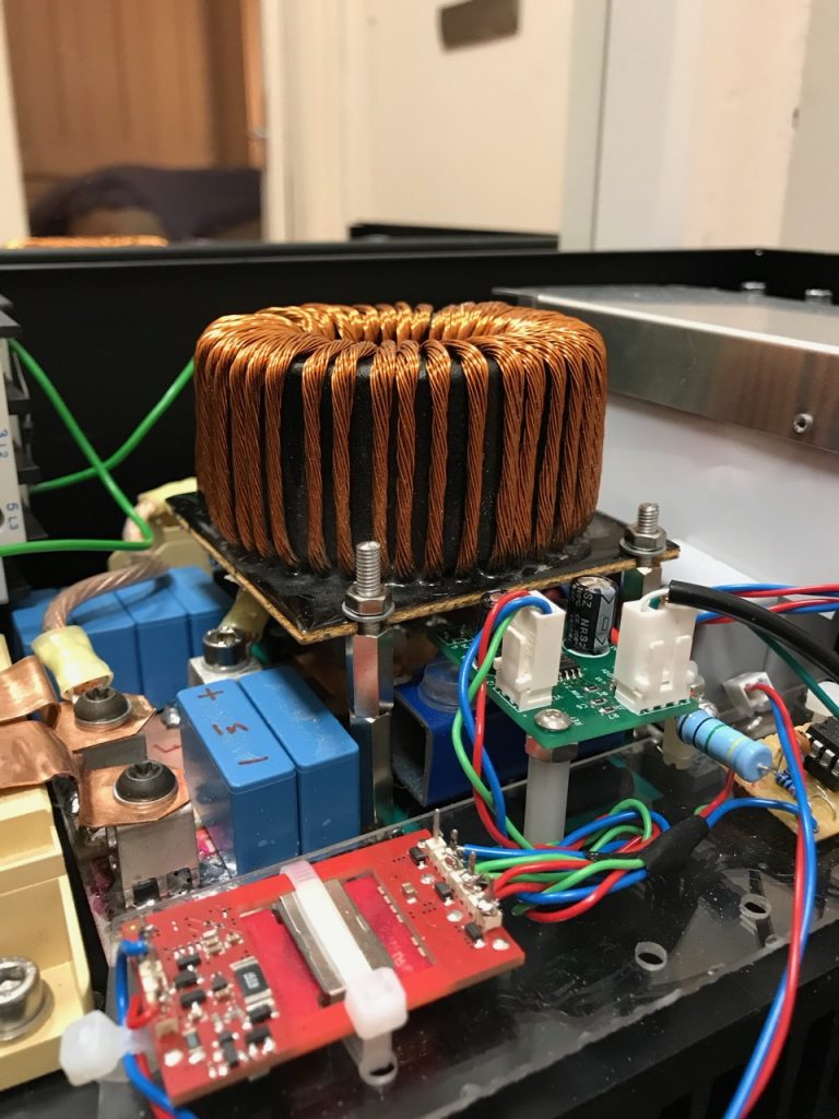
Luckily by using silicon carbide power devices, we were able to handle all the power we needed with a simple boost converter switching at 100kHz. No need for multi-phase or fancy energy recovery snubbers- it’s just a domestic appliance-sized PFC front end scaled up.
This means we can also use a controller intended for said domestic appliance PFC. I used the UCC28180 PFC controller chip from TI, because it only has 8 pins and is marketed as “easy to use”, therefore it can’t possibly go wrong! 😀
(OK, I bought the evaluation board and tested it with some Tesla coil-like loads before committing)
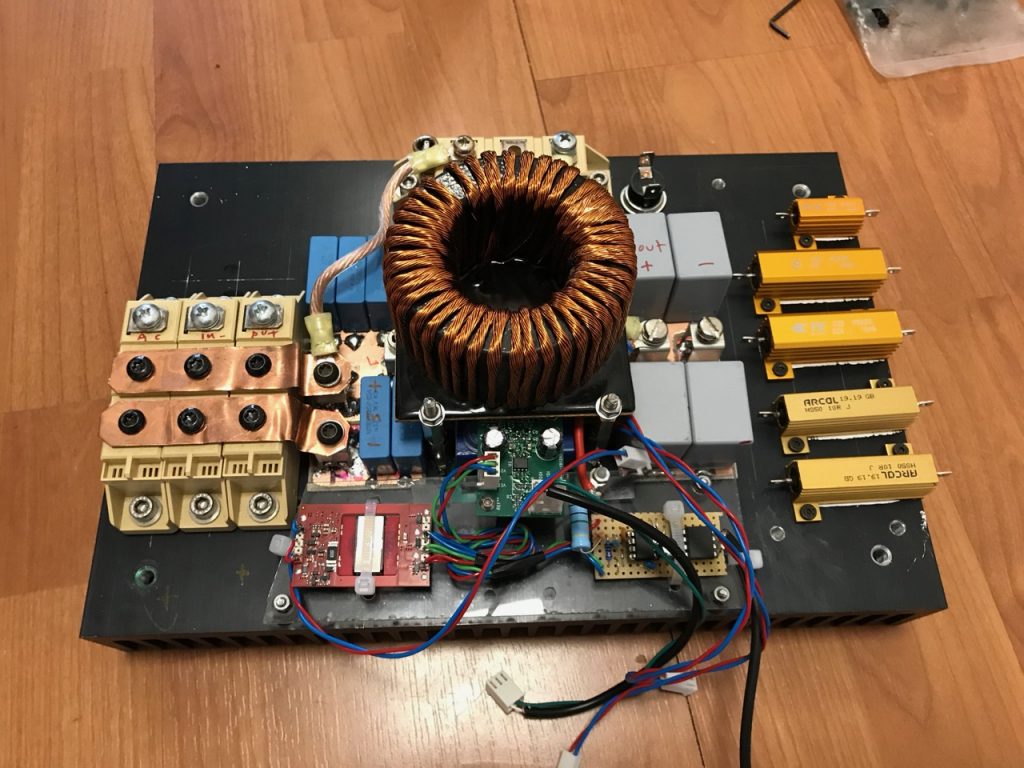
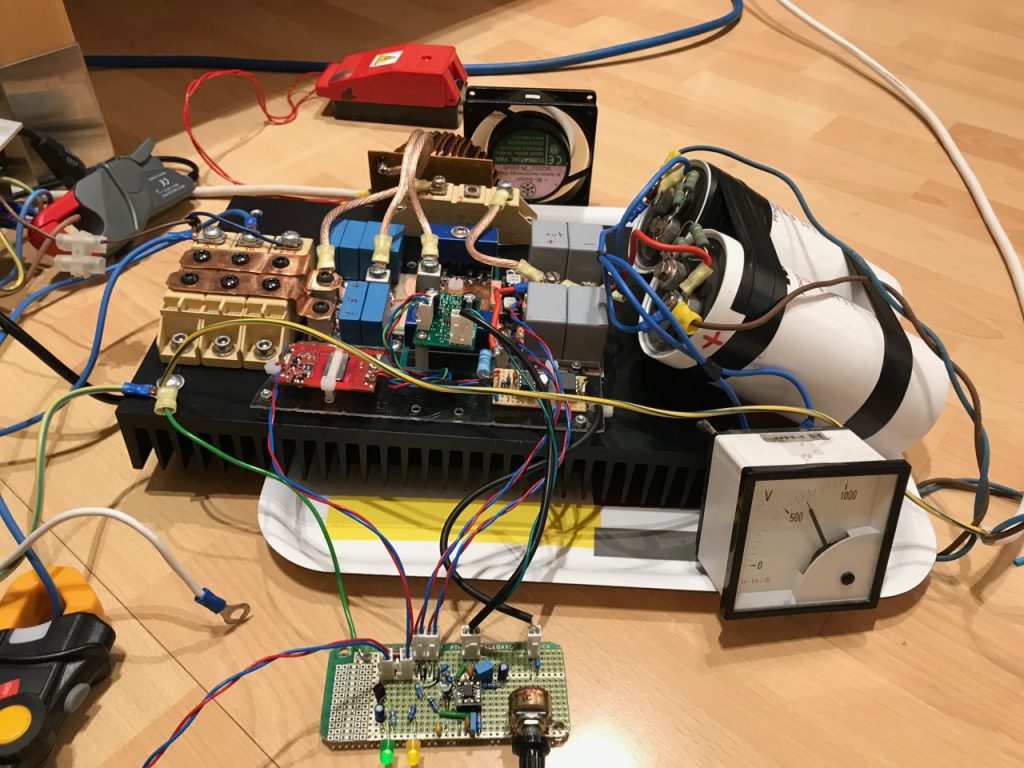
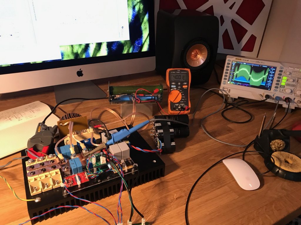
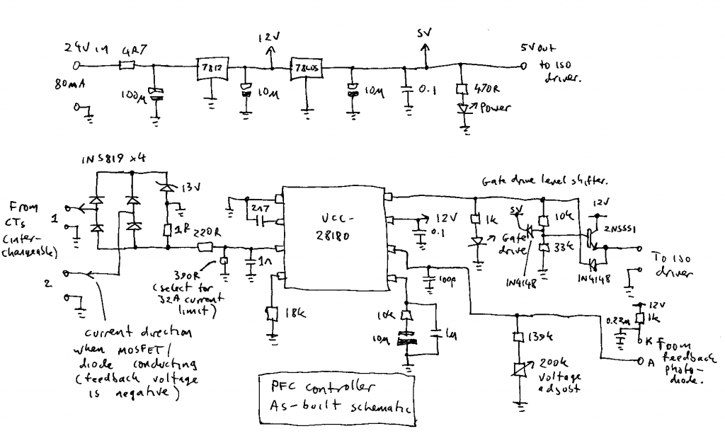
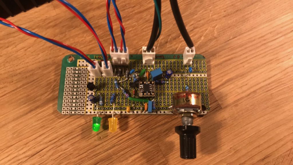
The PFC controller as built
This is the circuit I ended up using. It’s quite different to the original TI application circuit, so I’ll describe the differences.
Compensation: TI provide 2 full pages of formulae for calculating the compensation components, and ain’t nobody got time for that! So I took the values from the evaluation circuit, and doubled the capacitors and halved the resistor because it seemed like a good idea.
Gate drive: Silicon carbide MOSFETs need a negative gate voltage to turn off, and the UCC28180 doesn’t provide this, so I had to make a separate gate driver, which I’ll describe in the next post. The Silabs isolated gate driver chip needed a 5V supply and a 5V signal, so I had to add a level shifter and a 5V regulator.
Inductor current feedback: The UCC28180 is designed to take feedback from a resistor in the DC bus negative. This is a very common design choice in small PFCs. I added the 4x 1N5819 diodes and associated circuitry to adapt the signal from the CTs to look like it came from the original resistor. The 13V zener is used to clamp the spikes when the CT cores reset. A value of 13V guarantees reset even with the maximum duty cycle allowed by the controller chip.
I tested the CT feedback on the UCC28180 eval board before committing to building the full sized version, in case the chip turned out to be unhappy with it for some unforeseen reason, but it performed identically to the original resistor feedback, as far as I could tell.
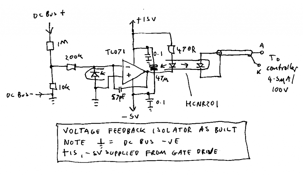
Voltage feedback: Since the CTs provide isolation of the current signal, and I ended up using an isolated gate driver, I decided to isolate the voltage feedback too so the control circuit would be completely isolated from the high voltage side. I used a simple circuit based on the HCNR201 linear optocoupler and a TL071 opamp.
Voltage feedback isolation circuit
The voltage feedback input of the UCC28180 has a high enough impedance that it can accept the current from the photodiode (4.5uA per 100V DC bus voltage) directly with no amplification or buffering. This simplifies the circuit considerably and provides some nice synergy. The UCC28180 has circuitry to detect an open feedback network, a dangerous condition that can cause the output voltage to run away, blowing up expensive pieces of power electronics. By configuring the voltage feedback in this way, the protection still works for an open circuit anywhere in the signal path, including forgetting to plug the isolator into the main board, and loss of power to the isolator’s opamp.
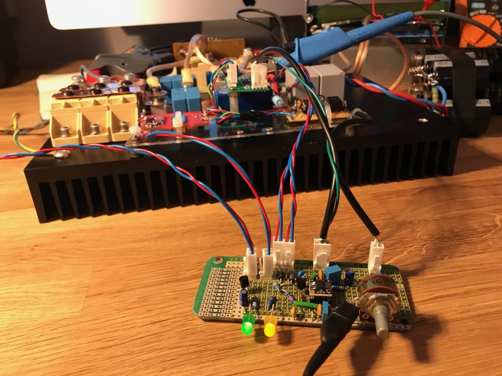
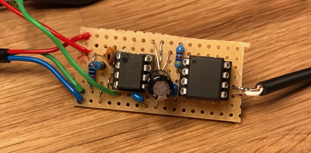
The controller. Knob is for output voltage adjustment.The voltage feedback isolator
Both circuits were easily constructed on protoboard with through hole components (and an adaptor for the UCC28180)