I decided it was time to build a new power supply for Odin with power factor correction. (See all posts on the PFC)
Power factor what? To explain, we have to go back to the turn of the last century and the War of the Currents. Alternating current won so all of our mains supplies are AC. However, solid-state Tesla coils, like most power electronics, run off DC. Odin needs several kilowatts of power at about 750V DC.
The simplest way to achieve this is to use a voltage doubling rectifier on the 240V AC mains. I used this in my previous large solid-state Tesla coil, the OLTC2, with one small refinement. I used SCRs instead of diodes to allow soft starting and varying the output voltage.
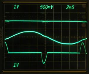
The major drawback of this circuit is a very poor power factor, especially at reduced output voltage. It is particularly bad in a DRSSTC, as it has a huge capacitor on the DC bus for energy storage, and the rectifier charges this directly. I improved the power factor somewhat by connecting a large iron cored inductor in series with the incoming mains. This worked well enough, and you can see details of the old power supply here here and here.

I used this same power supply topology in Mjollnir, Little Cook and Odin. There was no room inside the smaller coils for the passive PFC inductor, so I used a much smaller one, making the power factor even worse. The shortcomings really became apparent in a few shows I did with Odin. It performed really badly when running off a generator, and there were two venues with 3 phase supply that I couldn’t use.
After much thought I decided to go for the simplest possible solution: a boost PFC. These are very common in larger consumer electronics, and controller ICs and design information are readily available. It is also easy to modify for 3 phase input. Essentially you just replace the rectifier with a 3 phase one. The line currents aren’t nice sine waves any more, but the power factor is still greatly improved over a plain rectifier with the same filter capacitance.
Probably the biggest drawback for Tesla coil use is that the output voltage can only be greater than the peak value of the rectified input voltage. You are limited to a minimum of about 400V when running off 240V single phase, and 600V from a 415V 3 phase supply. This is a problem for me at least because I like to check the tuning at reduced voltage after setting the coil up at a new venue.
Eventually I persuaded myself that I could live with this and set to work designing a boost PFC.
Leave a Reply