When I started designing I already knew that the heart of the thing would be silicon carbide MOSFETs and diodes. I heard so much from Anders Mikkelsen of Advantics raving about how awesome they are. 🙂
On recommendation from Anders I chose the C3M0065100K MOSFET and C4D10120D diode. These are available from Farnell, Mouser etc. for about £10 each. I figured that 2 in parallel would allow me to run an inductor current of 32A RMS, a reasonable match to the mains supplies available in the UK and Europe. Anders also kindly donated an inductor capable of handling 32A RMS. 🙂
The remaining design decisions were set by the dumpster find of a large heatsink and set of 3 Semikron dual diode bricks. Having such a beefy oversized rectifier made short circuit protection easy: I just needed to come up with one more heavy duty diode to bypass the delicate SiC diodes, and then a short on the output would simply pop the circuit breakers on the mains input.
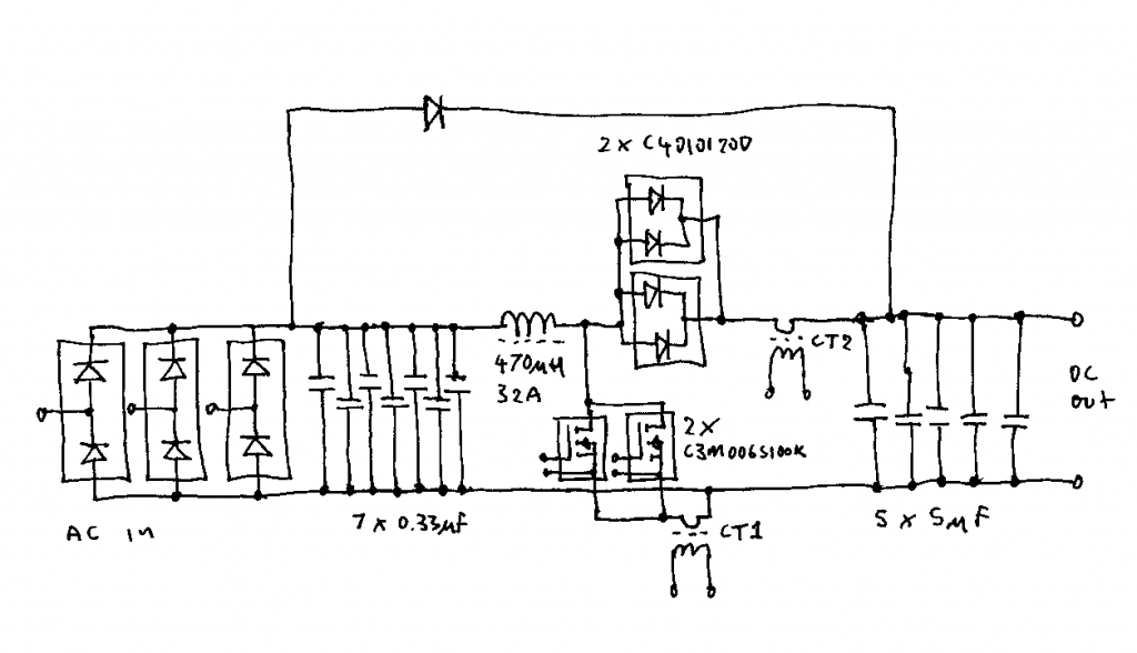
CT1 and CT2 are small ferrite cored 1:200 current transformers sensing the MOSFET and diode currents. Their outputs are combined in the controller to give the inductor current.
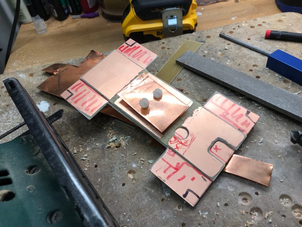
SiC MOSFETs can switch incredibly fast, so a good layout with minimal stray inductance is important. I decided to make a multi-layer structure out of pieces of single-sided copper-clad PCB and copper sheet.
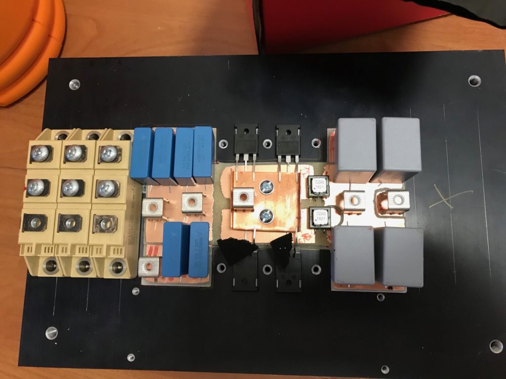
I didn’t manage to fit as many capacitors as I wanted: only 5 on the input and 4 on the output. The output ones in particular will have a hard time with serious amounts of HF ripple current. They are only there to filter out the HF ripple. Large electrolytic capacitors will be needed to handle the power frequency ripple, they will be mounted somewhere else and connected by wires.
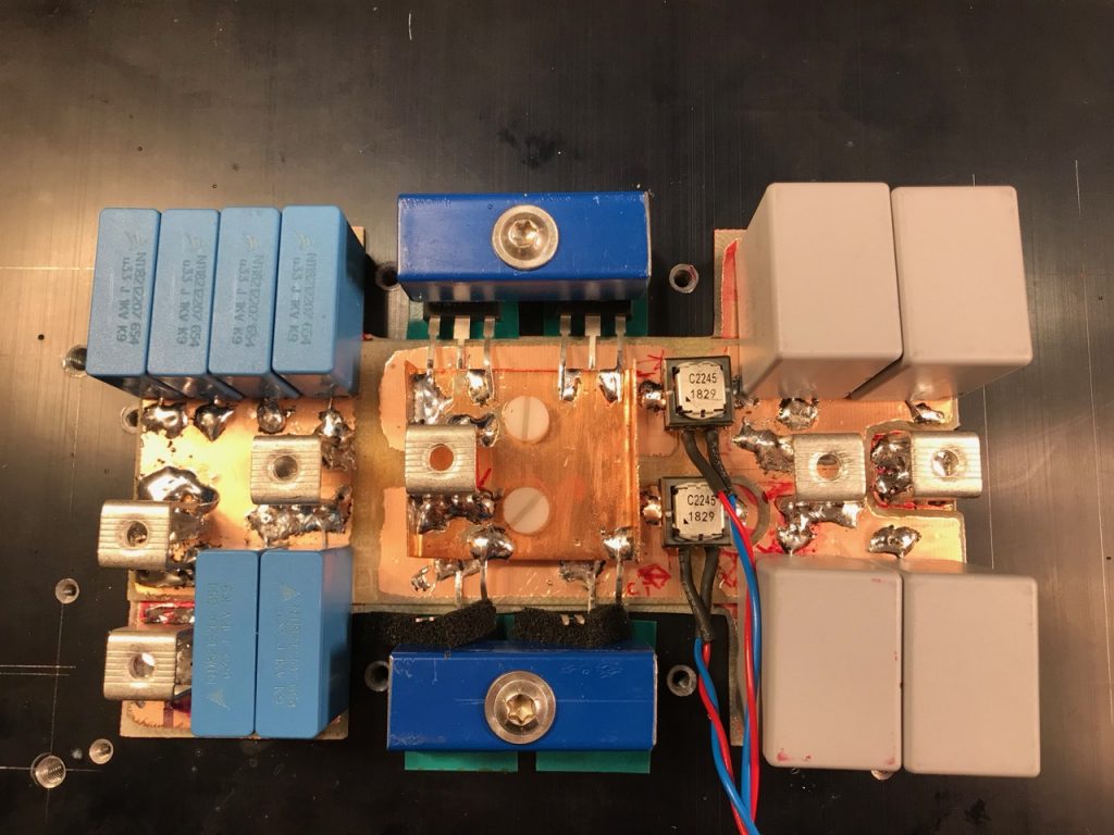
Clamps for the MOSFETs and diodes made from pieces of Ikea cabinet legs. 🙂
Leave a Reply