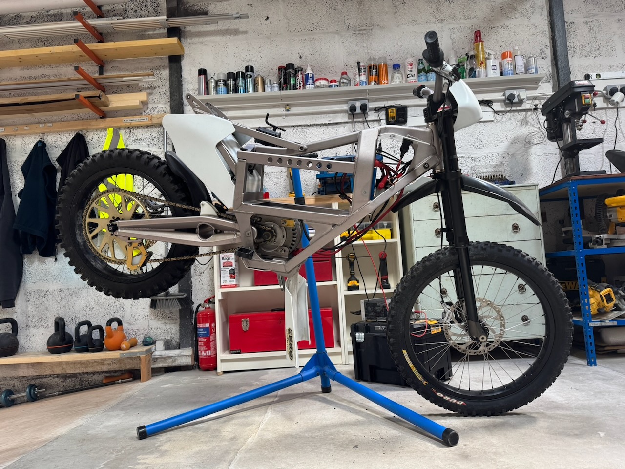
After a few rides of the Zero I became interested in how the throttle mapping works. There are two switches on the dashboard to select 25 or 50mph top speed and “low/high torque”. Regardless of the setting, the throttle response seemed quite aggressive and tricky to control at low speeds. I suppose this is partly the reality of having a 15kW electric motor in a relatively light vehicle, but it felt like there was more going on than that.
Zero updated the dashboard soon after the bike came out, and I got the old one, so I started by taking it apart.
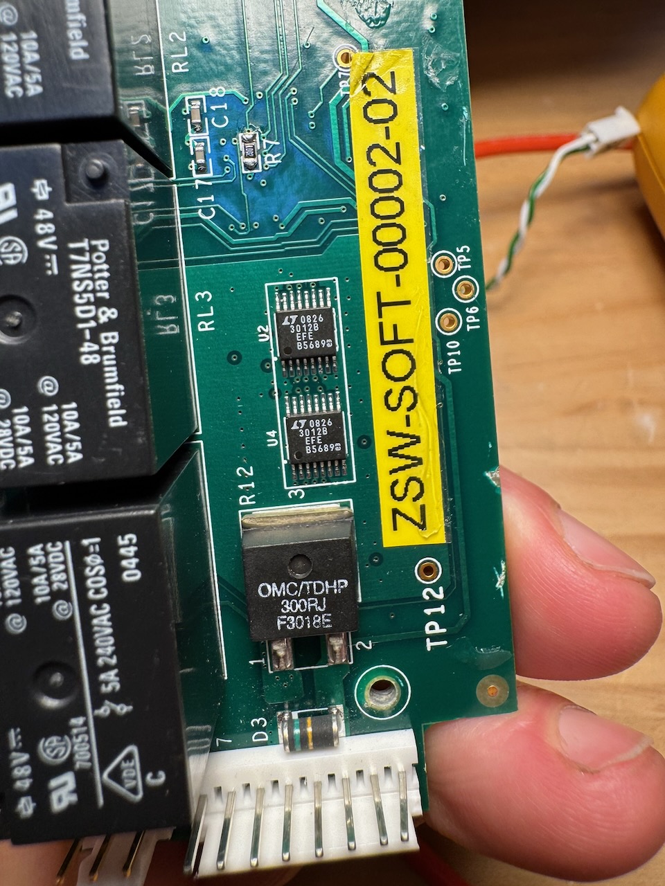
Oh no. It has software.
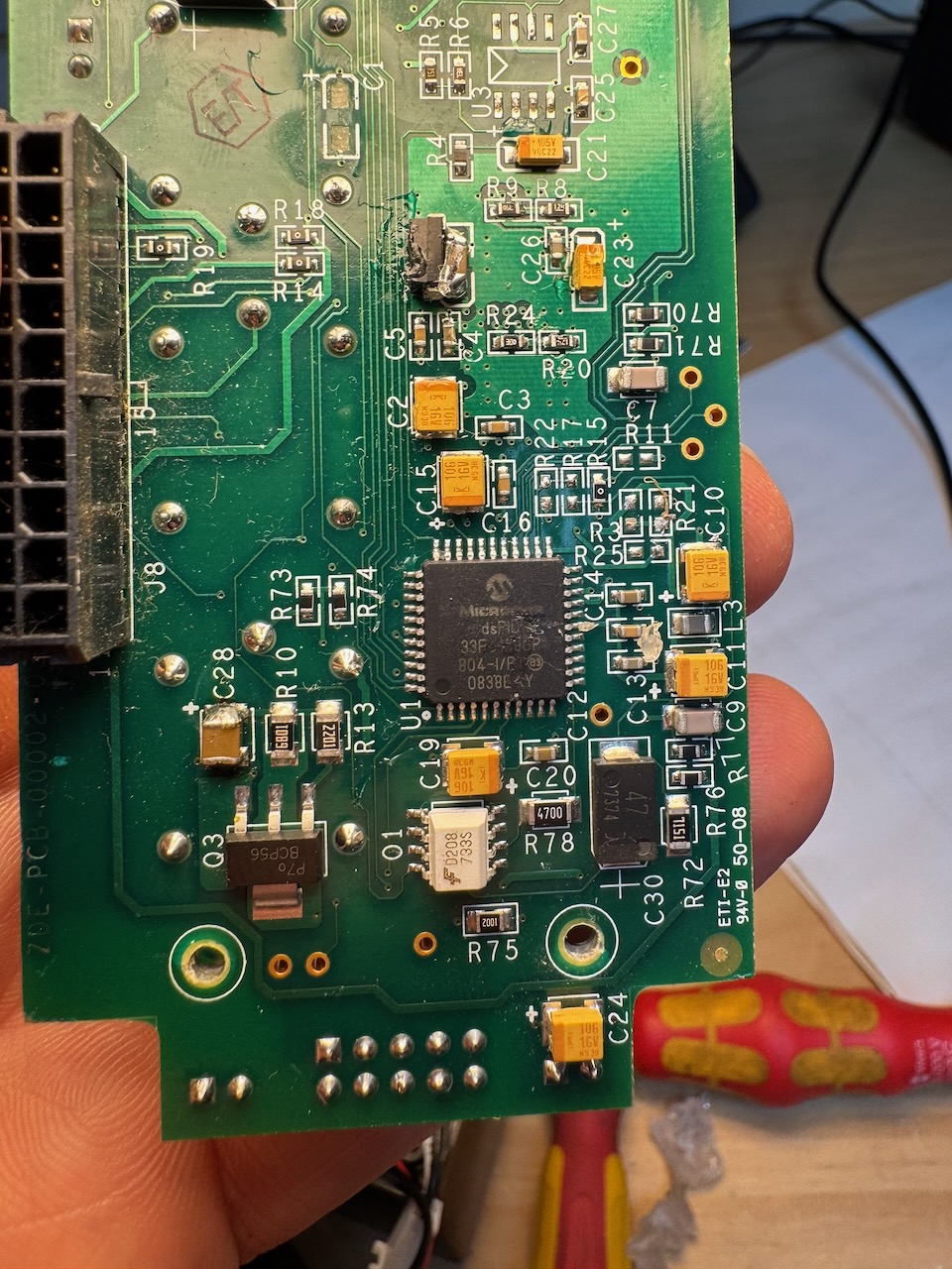
On the other side of this thick multi-layer board, a Microchip dsPIC. Quite a high end MCU for running a LED bargraph voltmeter. And it didn’t even run the voltmeter: that was a completely separate analog board made by 4QD.
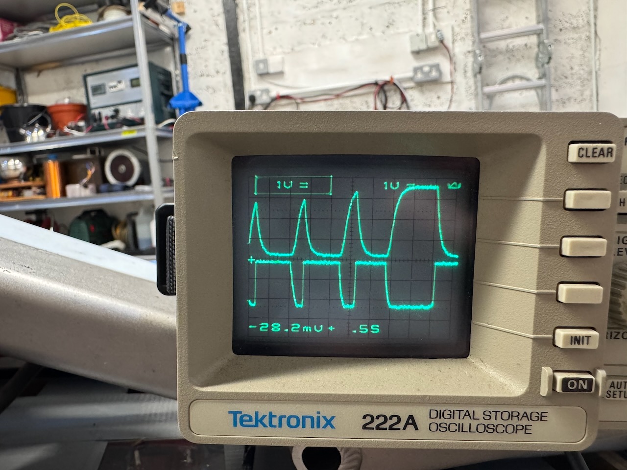
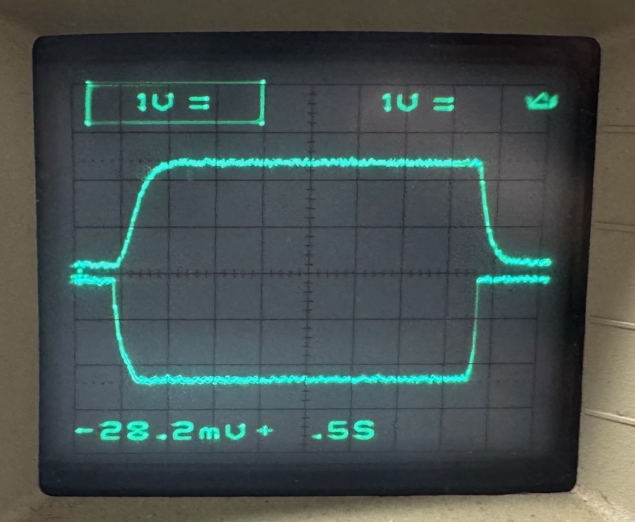
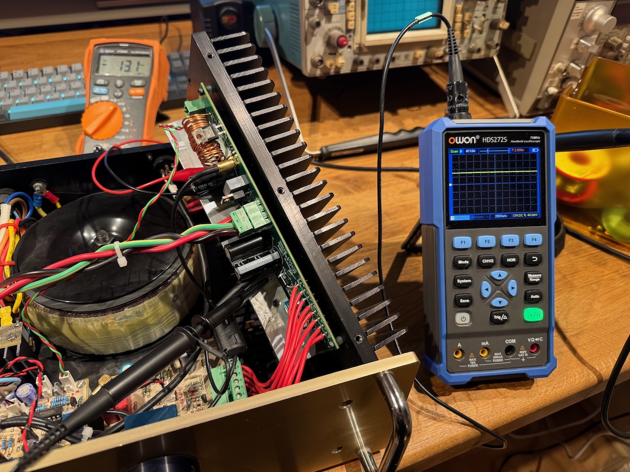
I dusted off my ancient Tektronix 222A (with no battery 🙁 ) and hooked the two probes up to the throttle pot and the motor controller’s throttle input.
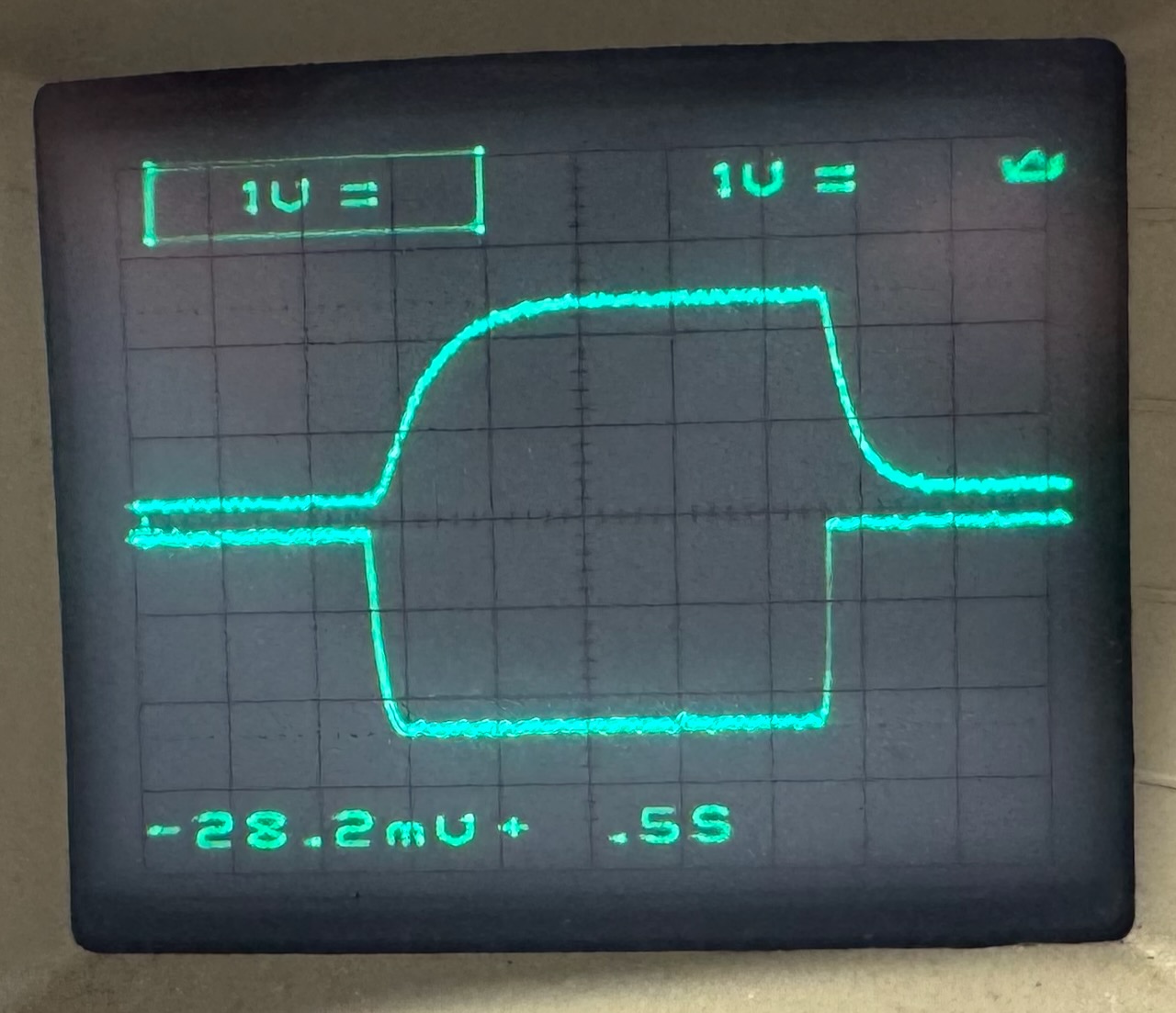
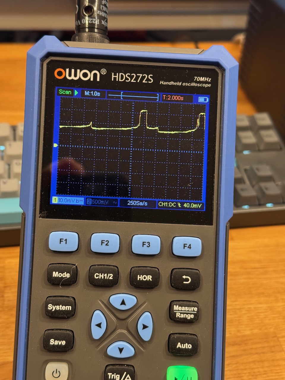
The bottom trace shows the throttle pot voltage, going more negative as it opens. The top shows the voltage output to the motor controller. Some kind of low-pass filtering is obviously going on: I whack the throttle open as fast as possible, but the voltage to the controller’s throttle input rises more slowly.
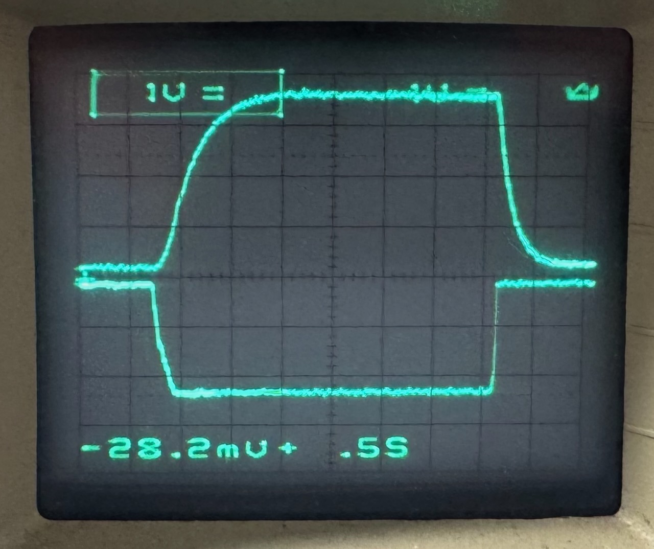
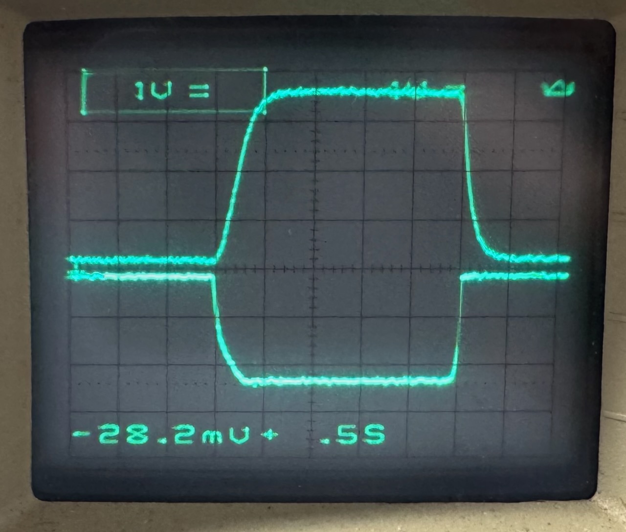
I repeated this experiment for the 4 combinations of switch settings. Luckily, the bike didn’t care if I disconnected the throttle input from the controller, so I was able to do this without the rear wheel spinning frantically on the stand.
25mph speed, low torque25mph speed, high torque50mph speed, low torque50mph speed, high torque
There are a few interesting observations here:
The 25mph mode just cuts the throttle demand voltage in half. Now in a modern EV powertrain, the throttle demand maps to torque. And cutting the available torque in half doesn’t halve the top speed. The reduction in speed would depend on grade, terrain, rider weight and so on.
When I rode it, I also noticed the acceleration from a standstill was just as aggressive in 25mph mode, but it suddenly dropped off around 25mph.
From this we can conclude that the controller is working in a voltage mode where the throttle demand just sets PWM duty cycle and motor voltage directly. This seems an odd way of doing things, though obviously it would make the controller design somewhat easier for Alltrax.
We can also see that the “low/high torque” switch doesn’t directly control torque either. It changes the time constant of the low-pass filter.
This does kind of influence motor torque if you squint at it. Newton’s law says that force equals mass times acceleration. If we take this into the rotational domain, and then into the electrical domain through a permanent magnet DC motor, we get that torque is proportional to the rate of change of motor voltage. The faster the motor voltage ramps up, the more current will flow, the more torque will be generated and the harder the bike will accelerate.
This is only true when considering inertial forces though, which is to say accelerating on flat ground. Regardless of the setting of the torque switch, the full torque is available for climbing steady grades.
So overall I think the Zero would be more rideable if it had a real motor current feedback loop that allowed the powertrain to operate in torque mode. I stand by my earlier description of it as a “giant demented cordless drill” because the direct mapping of throttle position to PWM duty is exactly how a cordless drill trigger works too. 🙂
The motor controller must have an internal current limit that overrides the throttle demand, but exploring that is for another post…
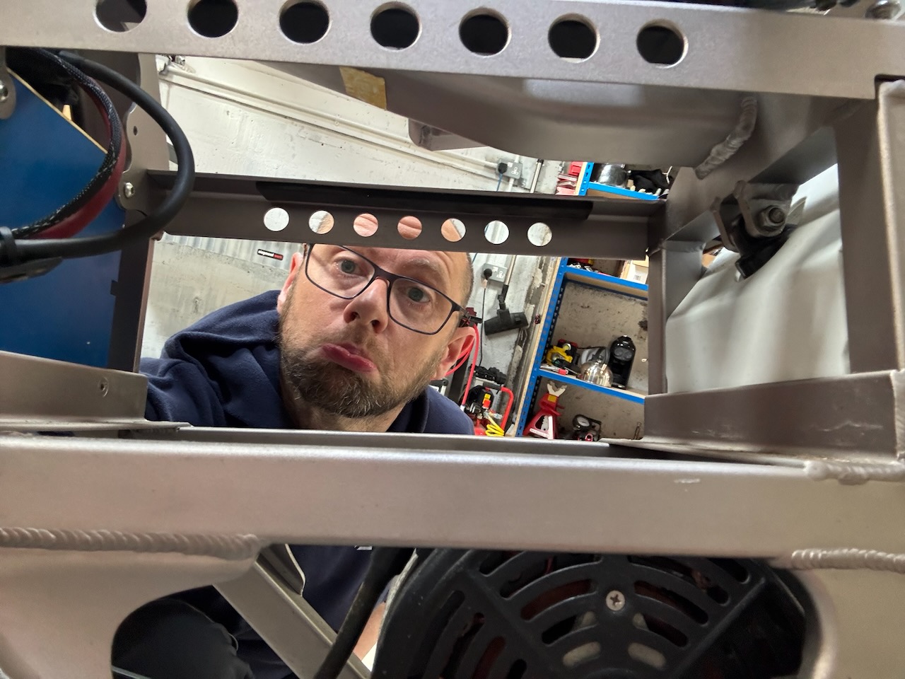
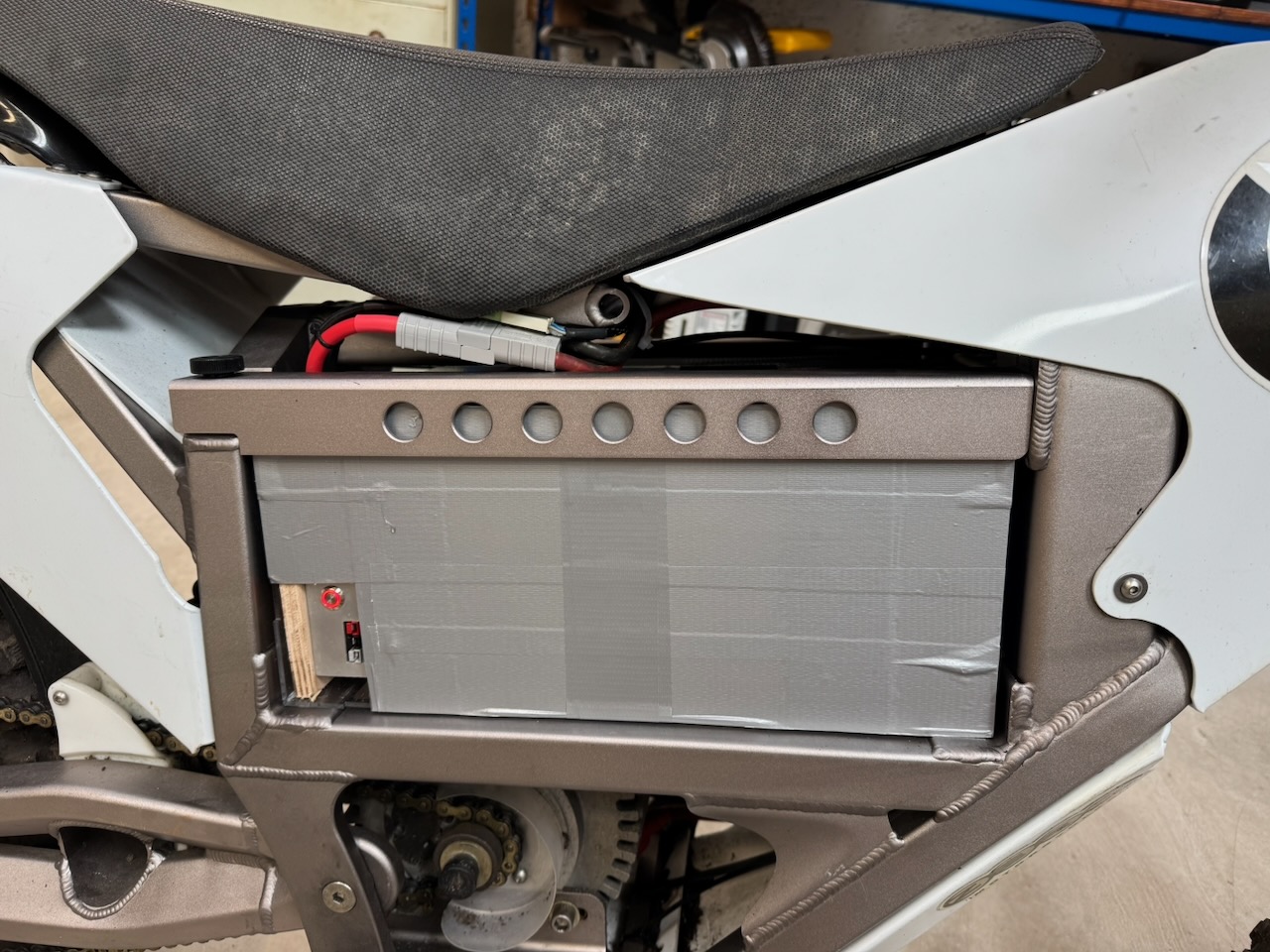
This electric motorcycle arrived at Conner Labs with a sad empty hole where the battery should have been.
The battery connected with a standard Anderson plug and another smaller 2 pin connector. Could it be some annoying custom BMS data connection? Or just a battery temperature sensor? I opened negotiations by stuffing a 10k resistor into the small plug and connecting a 48V power supply to the large one.
The dashboard lit up and the rear wheel turned, which seemed pretty encouraging.
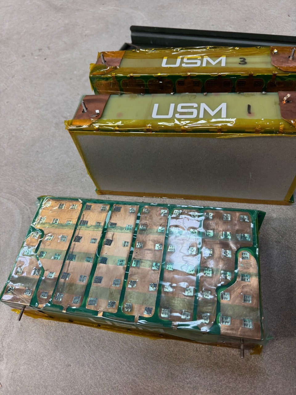
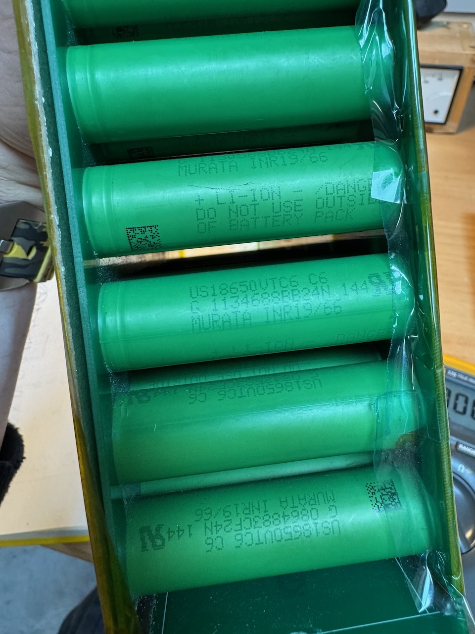
Ooh, Sony/Murata VTC6 cells, I wonder what state of health they are in?
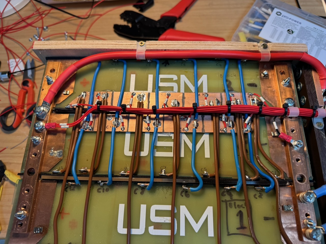
These modules are 14S6P, and in a stunning coincidence, the Zero’s original battery was also 14S.
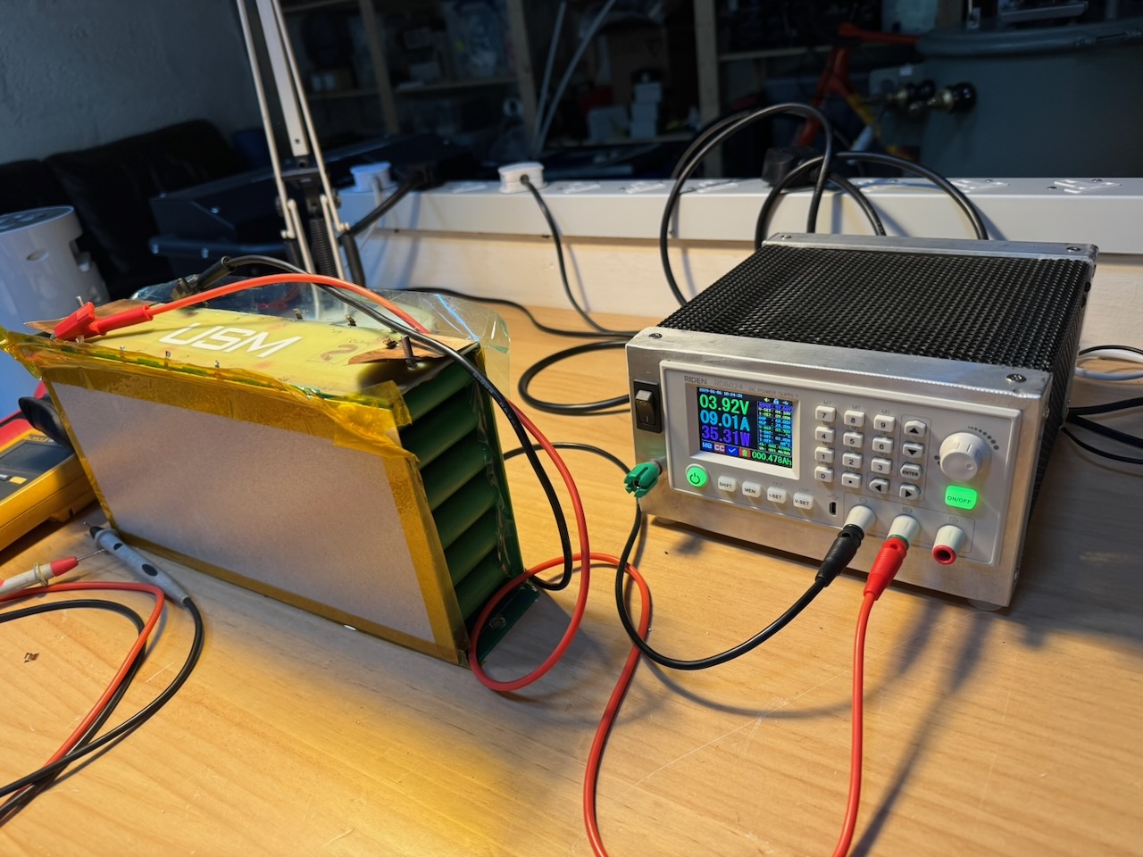
Using a bench power supply, I charged each section of each module to 4.1V. The Riden RD6024 has a dedicated battery charging terminal and tail current cutoff mode that hopefully made for more consistent results. The amp-hours needed varied wildly between sections, showing that the battery was indeed badly out of balance.
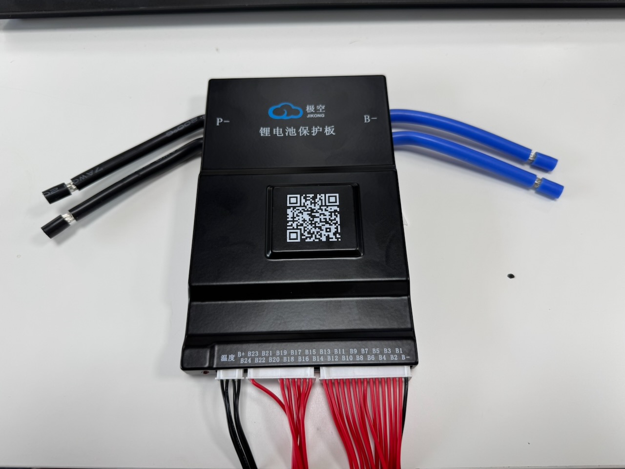
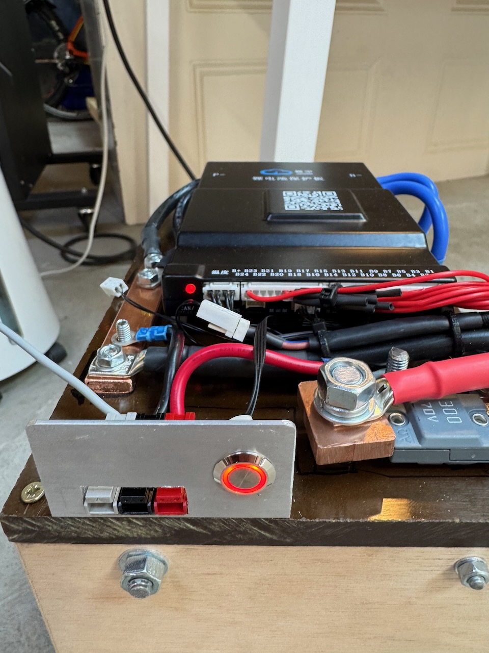
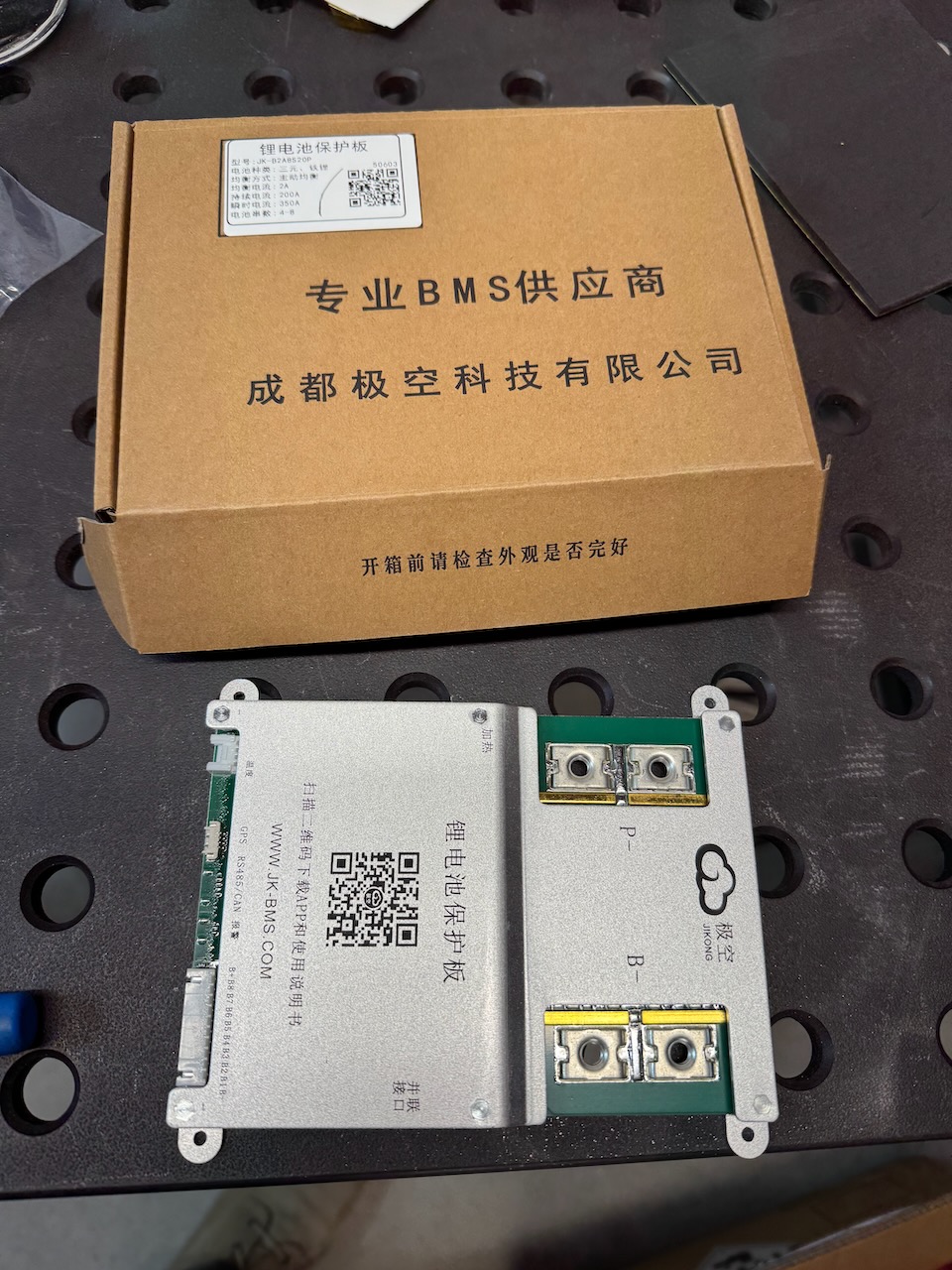
Once I could see that I had enough good cells to build a battery, I bought a BMS (JK B2A20S20P) This is rated at 200A continuous, 350A peak, and the bike’s controller (an Alltrax NPX) is rated 300A peak, so hopefully it will be up to the job. I’ve used the JK BMS before and it wasn’t a complete disaster.
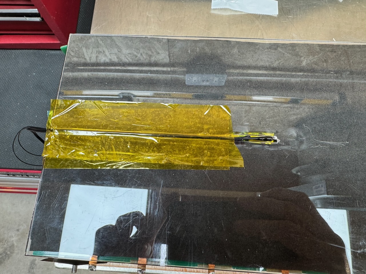
I got some laser cut acrylic spacers with slots for the BMS temperature sensors (and 2 more 10k NTCs, one for the bike’s dashboard and one for the charger)
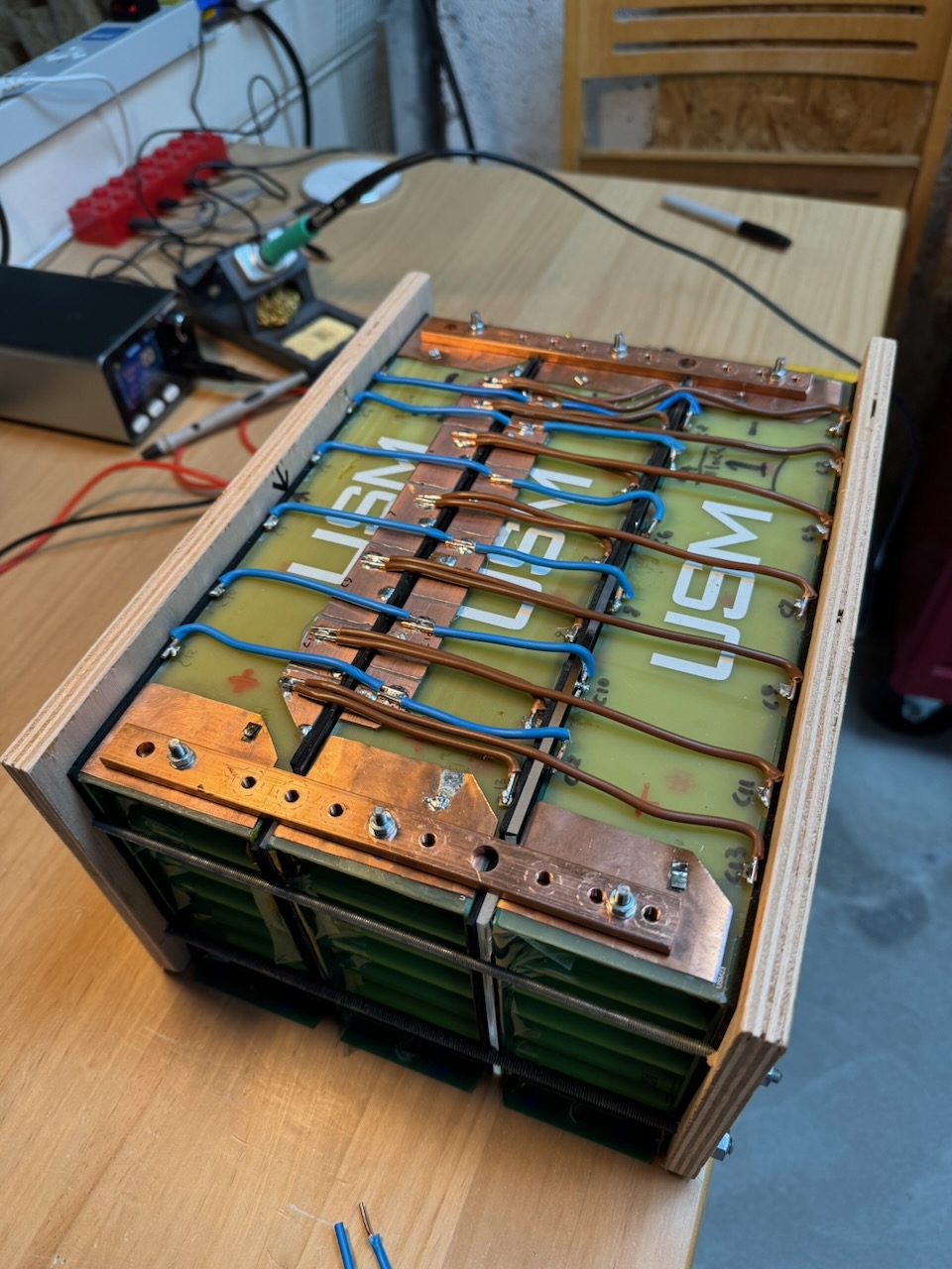
Then clamped it all together with some Plywood Aided Design ™ Just a temporary fix of course, if it fits the bike’s battery compartment and performs well, some more fire and water resistant material will be substituted in future. I promise lol.
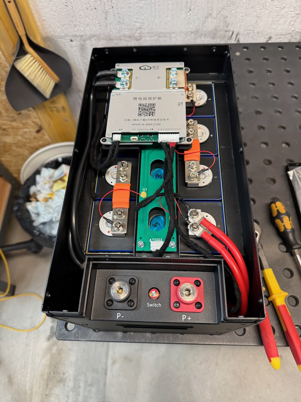
You might notice that I connected all of the cell taps of all of the blocks in parallel. The correctness of this approach is debatable :/ but I thought it was a reasonable compromise, compared to an individual BMS for each string.
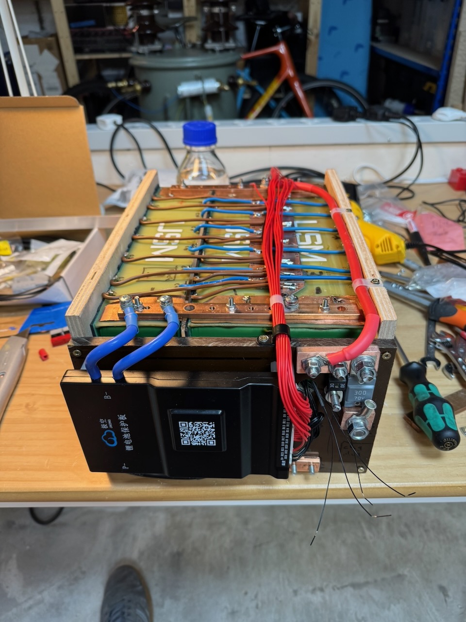
I mounted the BMS and fuses on a Tufnol end plate. Even for a temporary fix we can’t risk these coming loose and causing a short circuit.
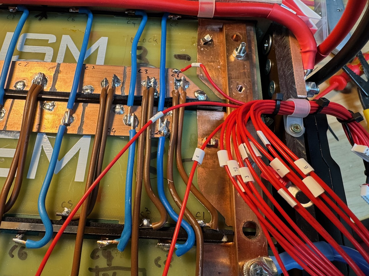
The days of marking wires with splodges of permanent marker are over at Conner Labs.
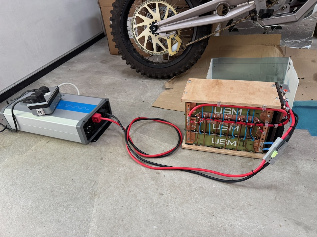
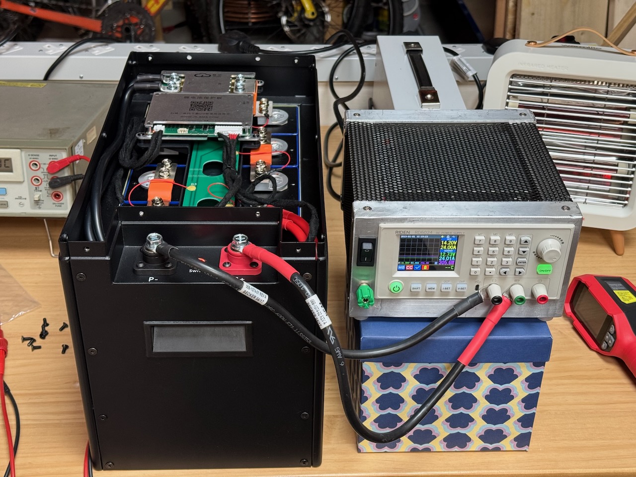
Soon it was time for the battery’s first cycle, for which I borrowed a 48V inverter as a load.
With 2500W of load on my 50V, 54Ah battery I expected it to last a bit over an hour. At this point there was a slight disappointment as the discharge was ended by cell 3 undervoltage at only two-thirds of the expected capacity. 🙁
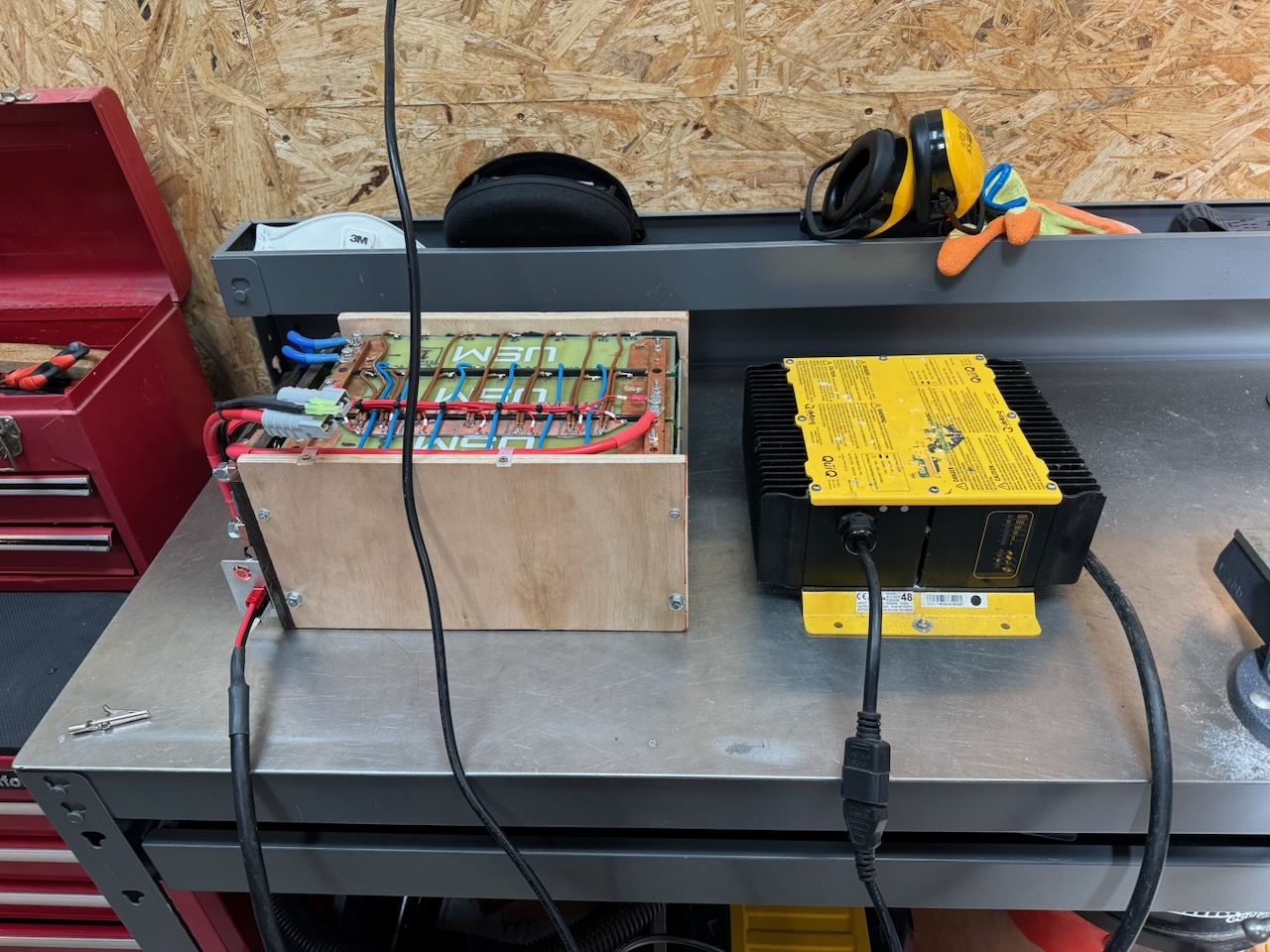
Then it was time to attempt a recharge with the Delta-Q QuiQ charger supplied with the bike. It would sometimes cut out at random with a sequence of flashing lights that wasn’t documented anywhere. For future me and others reading, the white wire is not for a temperature sensor! Just connect it to the black one to make the charger run.
Also, these chargers have programmable firmware with a selection of different algorithms. Mine were labelled lead-acid but had been reflashed with a custom “algorithm 99” that was in fact for 14S lithium ion.
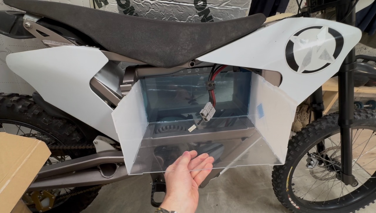
The project was “completed” (?) with a laser cut acrylic outer enclosure and a generous wrapping of duct tape.
[In this episode of the Chinesium Mine, we dabble in the home energy storage market]
I’ve loved playing with batteries ever since I was a kid, except for one horrible incident with a Burgess Safari Lite battery that put me off testing them with my tongue for life. More recently, electric vehicles and grid-scale battery energy storage have become A Thing, and all have standardised on the lithium iron phosphate battery (aka LiFePO4, LFP) so I thought I’d better get one for professional development. 🙂
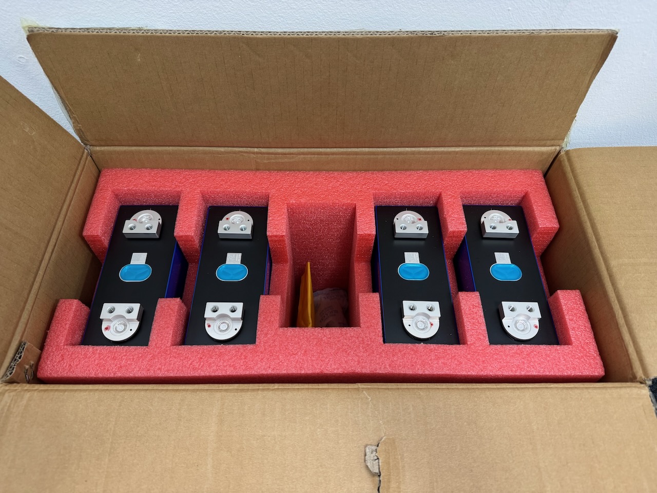
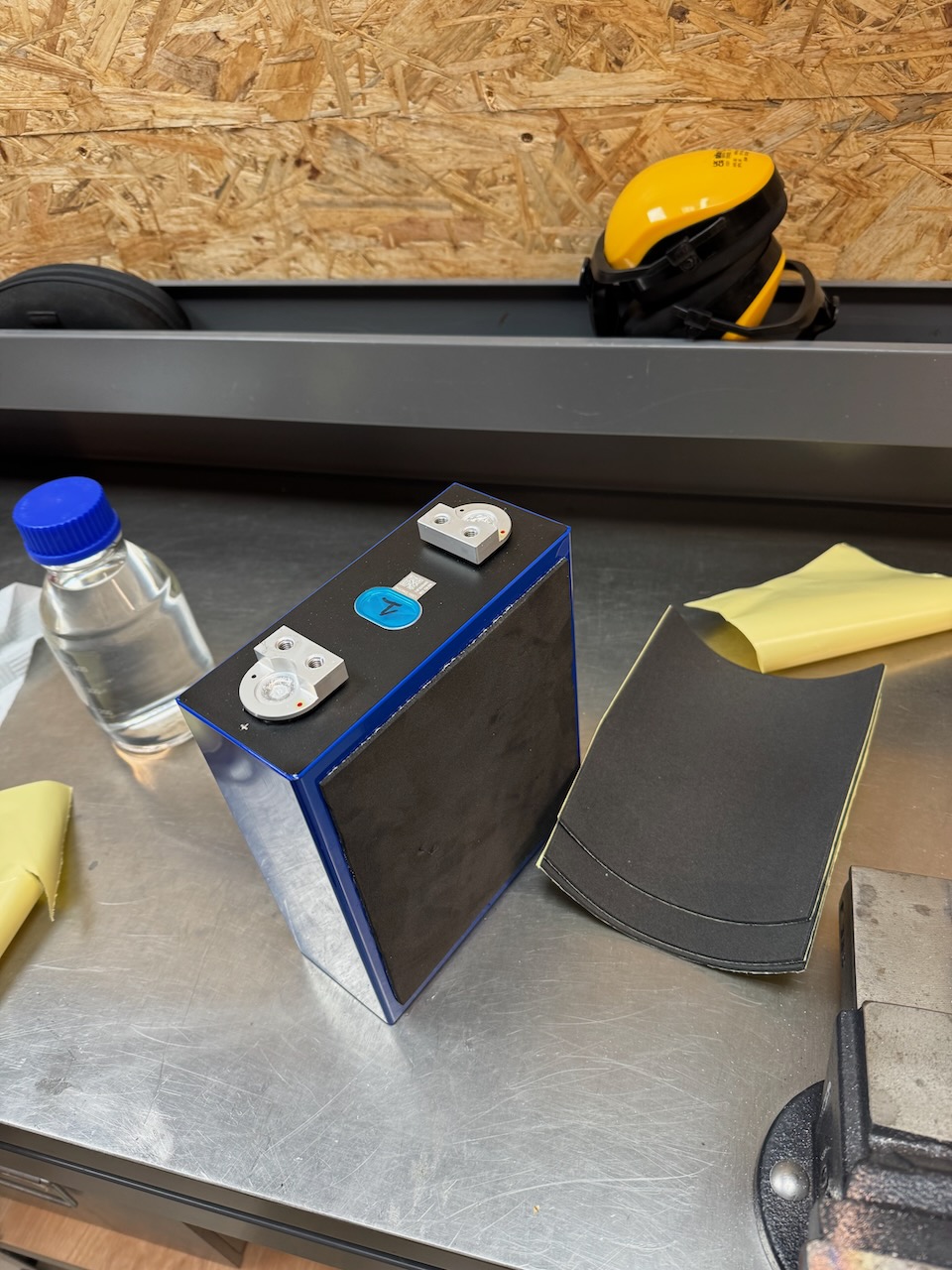
Besides 100 different types of vape battery, Fogstar also sell large prismatic LFP cells and all kinds of accessories to build your own battery pack. I opted for their 12V DIY bundle with the EVE MB31 cells. Shipping 20kg of lithium ion batteries could have turned into a nightmare, but they were delivered with absolutely no hassles.
A word of warning: Similar LFP cells can be found very cheaply on Ebay, Amazon, AliExpress, but buyer beware. There are a LOT of factory rejects and pulls from failed battery packs out there. I was reasonably confident that the Fogstar ones would be good.
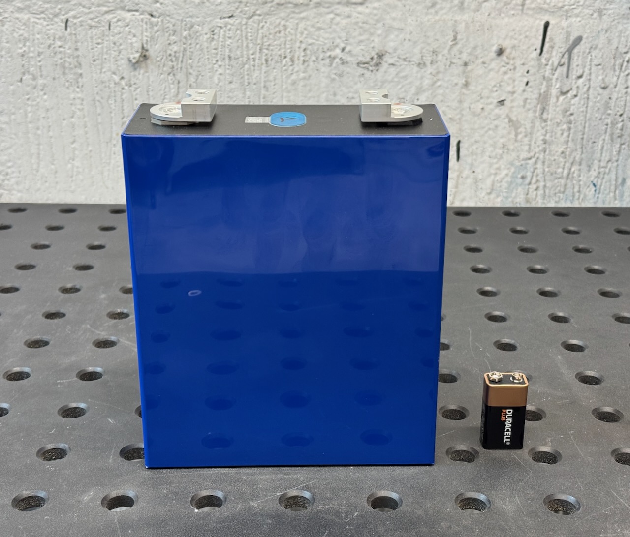
At only 3.2 volts each, the risk of another Burgess Safari Lite incident is minimal.
It’s not all about voltage though. These have a capacity of 314 amp-hours and can deliver a lot of current.
After doing some experiments with the raw cells [document in future and insert link] it was time to assemble the kit.
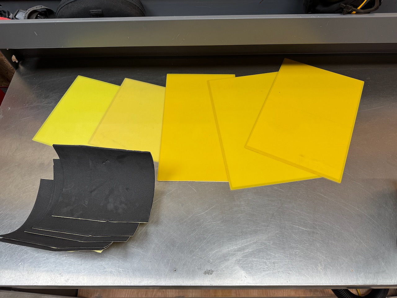
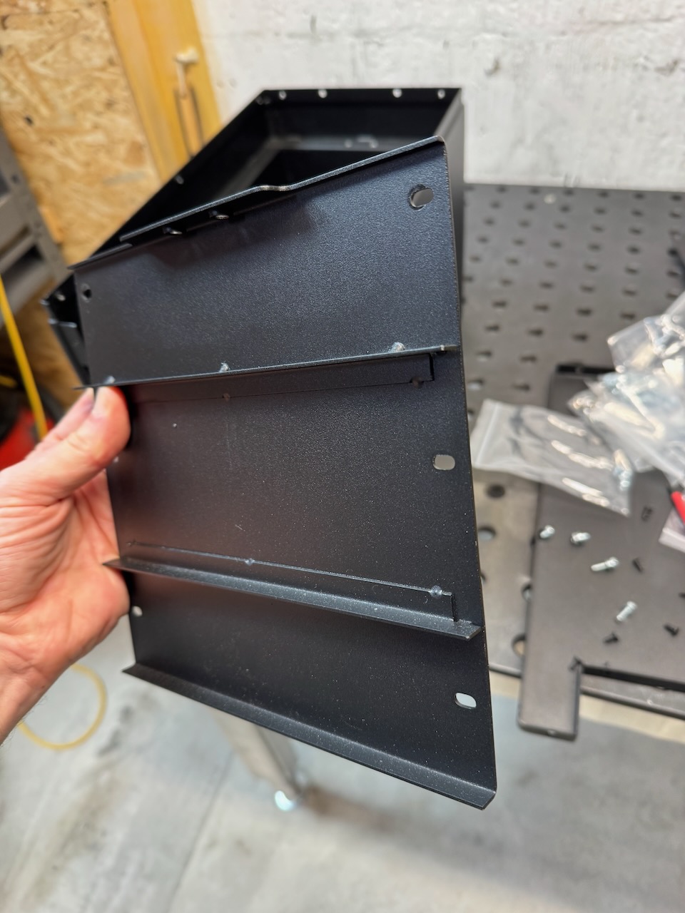
Internet best practice says that the blue plastic wrap can’t be relied on for electrical insulation, and the manufacturers say that the cells need some pressure applied to their broad sides for optimal cycle life. The Fogstar kit covered both of these bases: FR4 glass fibre sheets were supplied to line the metal battery box, and foam pads to go between the cells. All sticky backed for Blue Peter nostalgia.
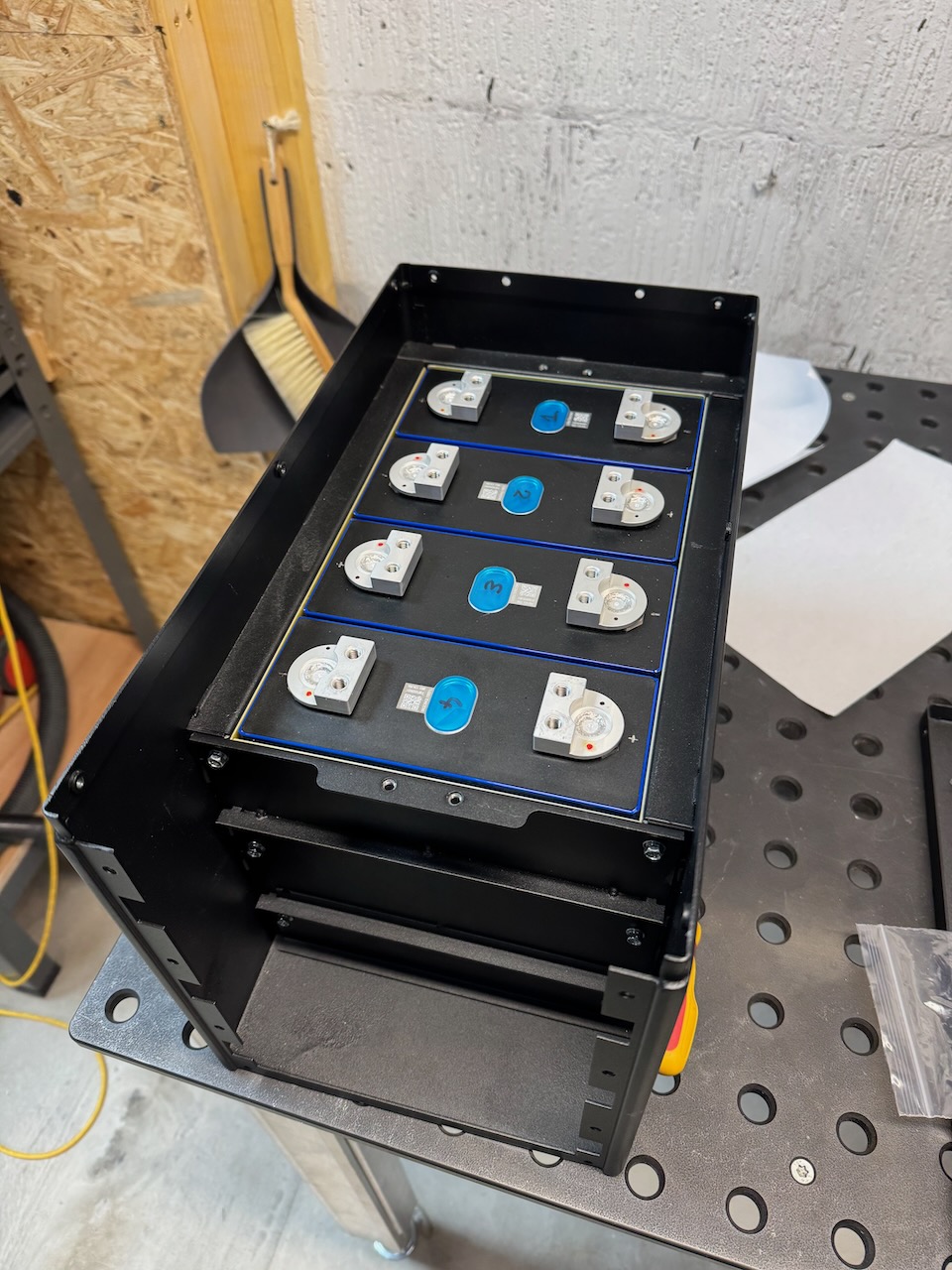
EVE’s recommended compression force for their cells is 300kg! I’d be surprised if this metal plate and its 6 screws were up to that amount of force.
Having said that, it did seem to squish the foam pads down a bit and clamp the cells in place firmly.
The next step was to fit this clamping bar over the tops of the cells, complete with a sticky backed foam gasket on the underside. The main purpose of it seems to be to stop the cells falling out if the battery is turned upside down. (At this point it’s worth mentioning that LFP cells are completely sealed and won’t leak electrolyte unless something goes very badly wrong. I’ve seen them mounted in almost all orientations, but they probably work best with terminals up.)
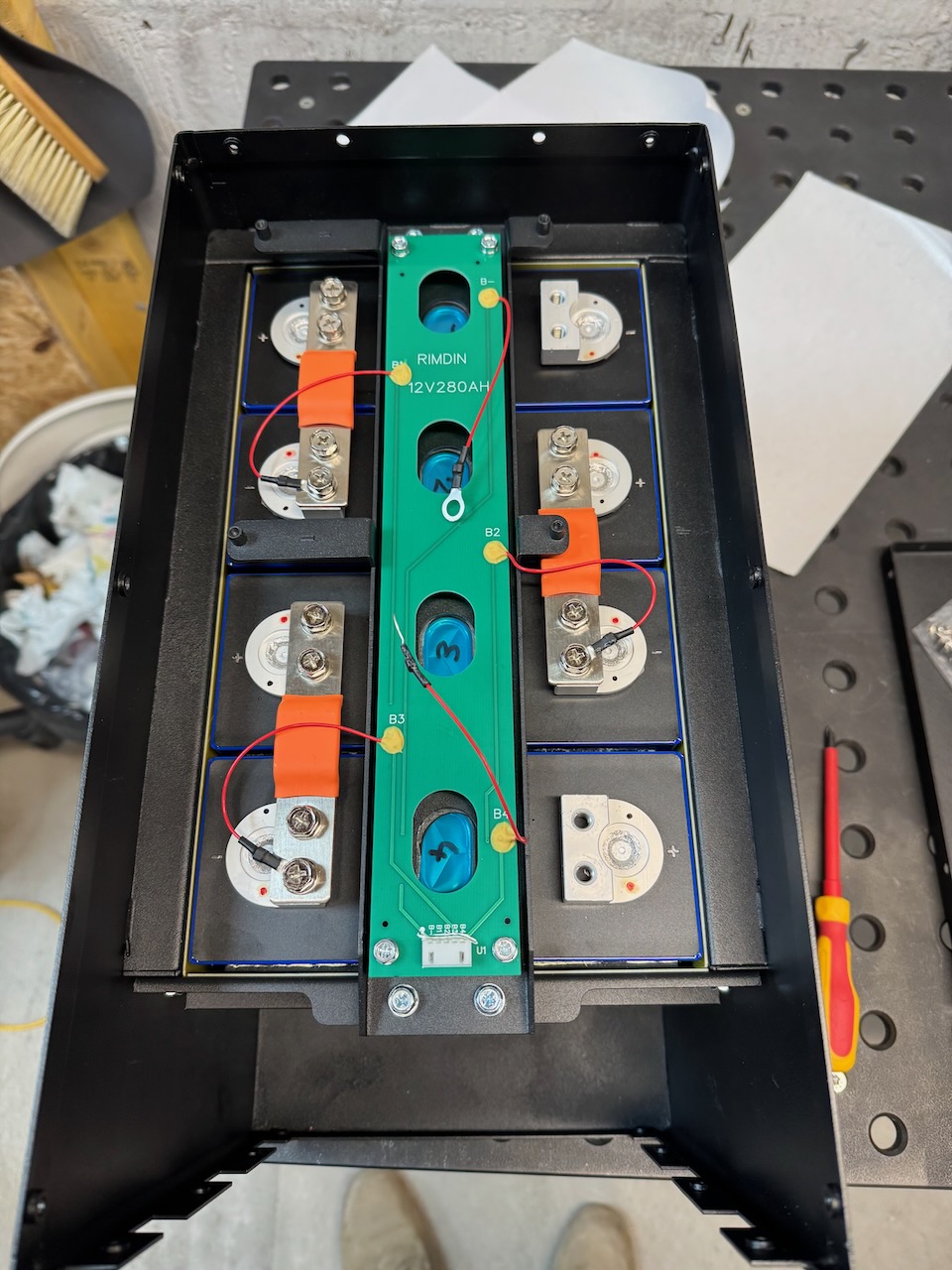
They are also rumoured to expand slightly as they charge. For my 12V stack, it probably works out to less than 1mm of expansion between empty and full. This is why the busbars supplied with the kit are flexible.
LFP are similar to the other lithium ion chemistries, in that they have no ability to self balance, and no tolerance of overcharging or discharging to very low voltages. A single incident can turn your new cell into a “spicy pillow“. The cell bloats up with gas and is ruined for good.(though to be fair, LFP spicy pillows are much less likely to catch fire or explode than the other chemistries)
To make sure the cells stay nice and prismatic, we need a BMS. The two most popular brands seem to be JK and JBD. My bundle included a JK 200 amp model with 2A active balancer.
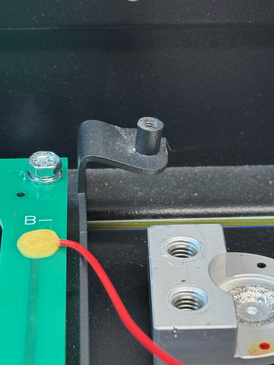
The mounting locations for the BMS needed a bit of gentle adjustment with a screwdriver, hammer and pliers. Out of the box, the BMS sat too high and the busbar connecting it to cell 1 negative put a lot of strain on the circuit board.
I liked the terminals and cable/wire harnesses supplied with the kit.
They even included a 400 amp ceramic Mega fuse in case the BMS overcurrent protection fails. LFP might not be prone to catching fire themselves, but they most certainly can supply enough current to start a fire.
Now came the hardest part of the build, did I mention that I’ve had enough of dodgy software to last me a lifetime? The BMS is configured and operated over Bluetooth by a smartphone app. It has two passwords, one to view status, and a different one to edit the settings. And nowhere do JK tell you what the default passwords are, or even that there are two. (For future reference, the view-only is 1234 and the settings password is 123456)
Victron use a Bluetooth PIN on their gizmos and notify you right in their app that the default is 000000. But their equivalent LFP battery costs 4x what this one did…
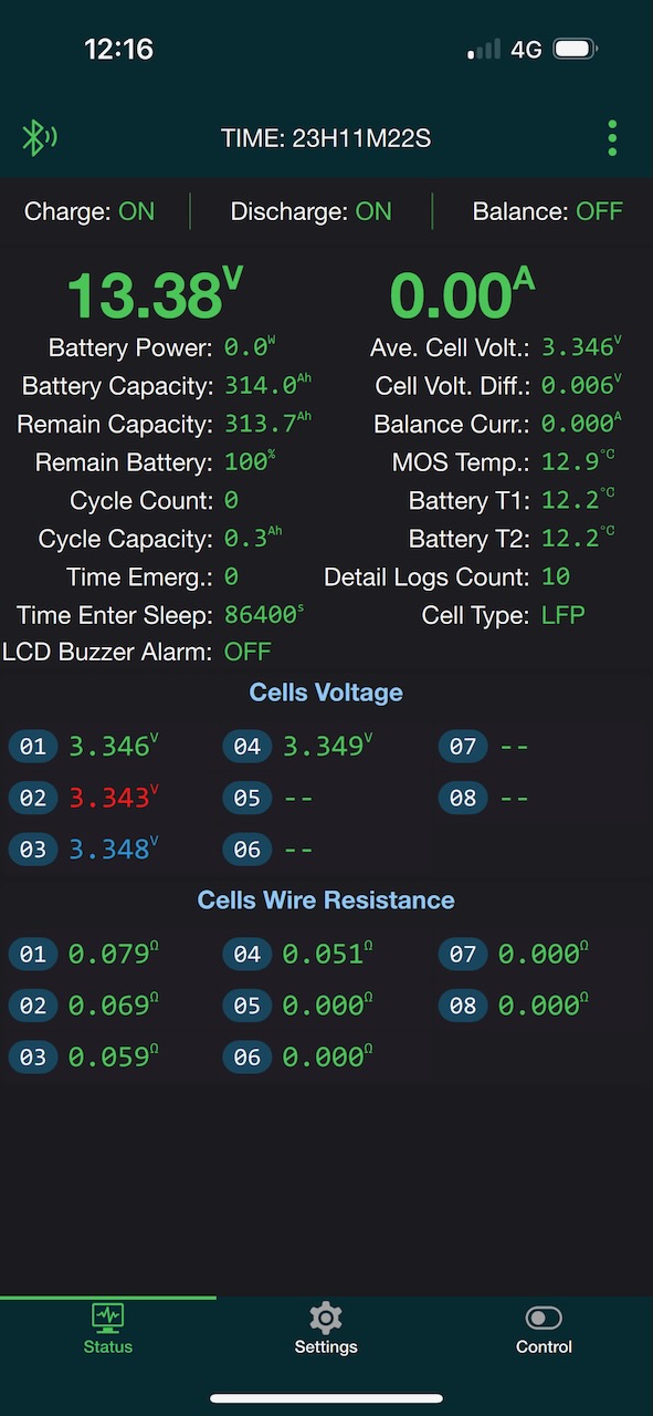
Eventually I got into it and was able to select the LFP battery type and enter the actual capacity of 314Ah. To be fair, the JK BMS app seemed pretty good apart from the out-of-box experience with passwords.
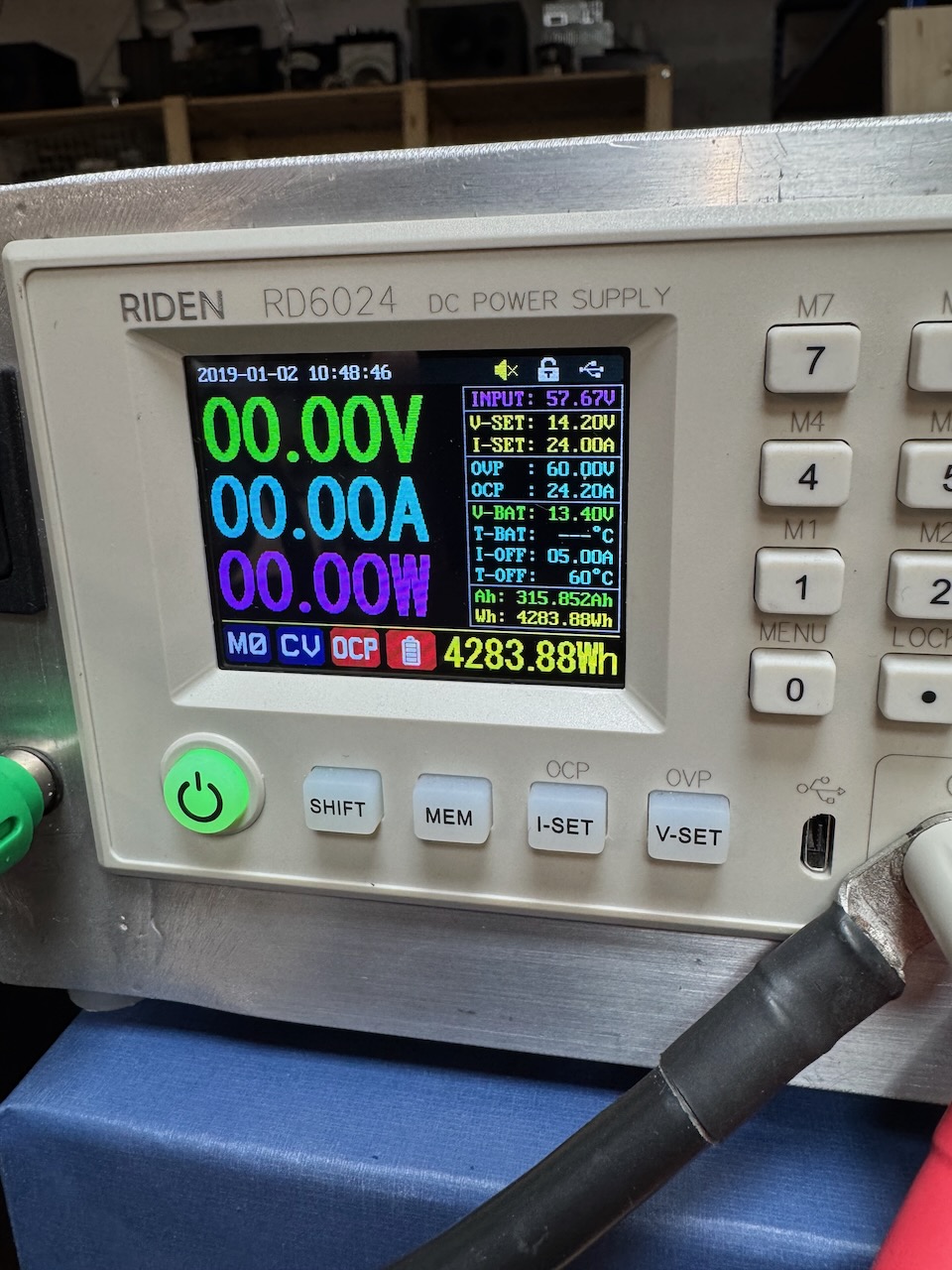
Then the first charge could commence… I set the Riden RD6024 (another golden nugget of Chinesium) to 24A, 14.2V, and a charge termination current of 5A.
Screenshot
With 24A into an almost completely empty 314Ah battery, the first charge took rather long. When I came back the next day it had finished, and both the Riden and the BMS showed almost exactly 314Ah input to the battery.
Screenshot
Which was oddly satisfying 🙂
All in all, this is one serious piece of Chinesium. The cells were brand new with no signs of previous use or tampering with the QR codes. They were very well matched and delivered exactly the advertised capacity. The BMS worked out of the box and its voltage, current and capacity measurements were reasonably accurate.
And the kit came from a UK dealer and has a warranty! It hardly even qualifies as Chinesium, except that the cells and BMS are so proudly made in China. Did I mention that China absolutelycorneredthemarket in LFP?
It just misses out on the highest grade because there was no documentation whatsoever. Like none.
I’m a fan of the Riden RD60xx series of power supplies. They definitely qualify as Chinesium, but a fairly high grade. They come as a small panel mounting unit that functions as a non-isolated buck converter. Riden also sell cases for them and a few different switchmode power supplies to feed the module with bulk DC.
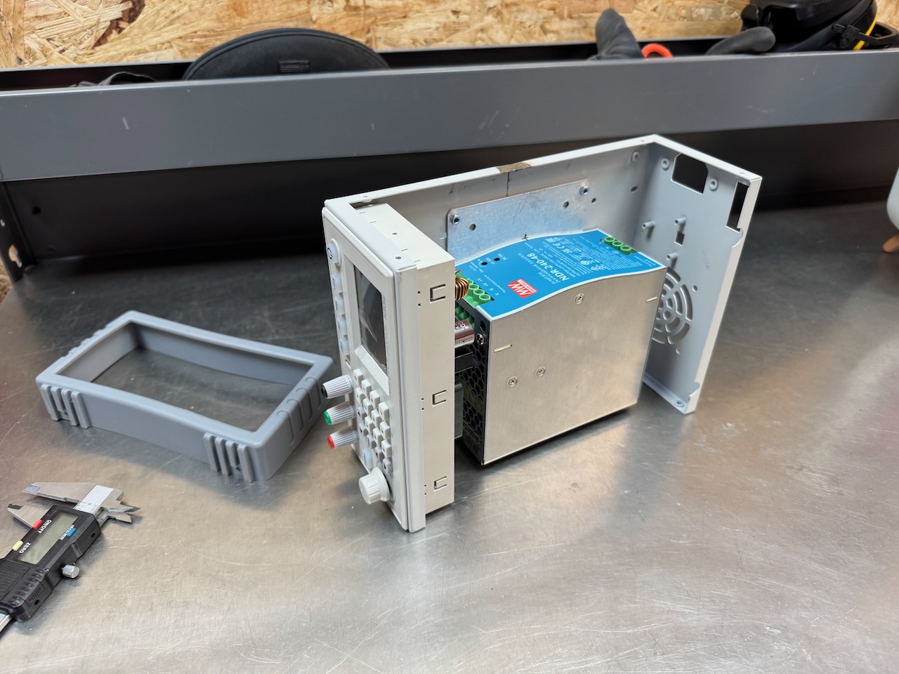
To build this one I used the RD6006P module, a 60V/6A version that claims to have a linear post-regulator for low noise, paired with a Meanwell NDR-240-48 switchmode power supply. This came from CPC, and all the other parts were sourced from AliExpress.
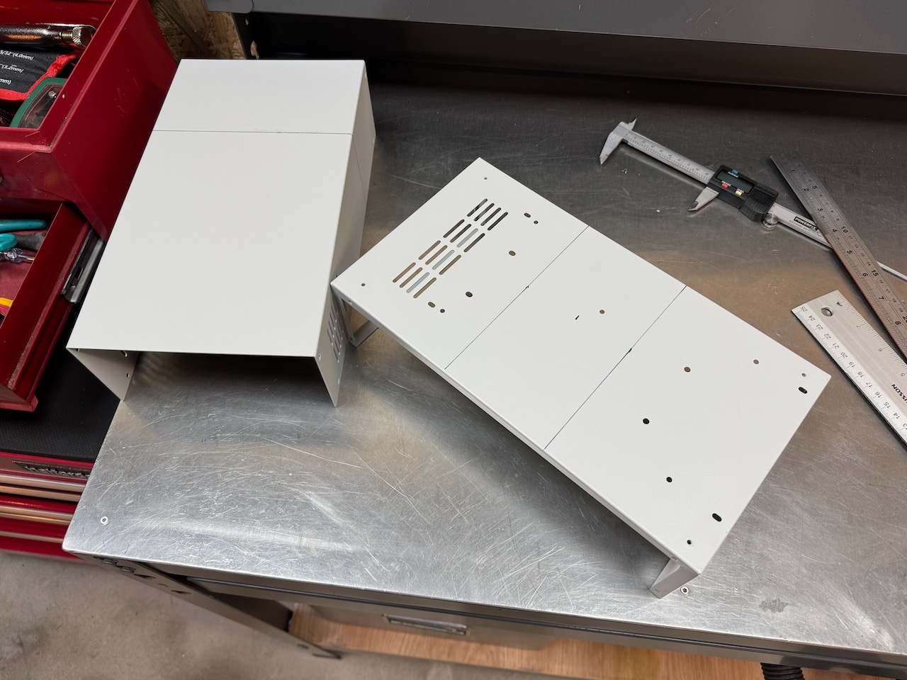
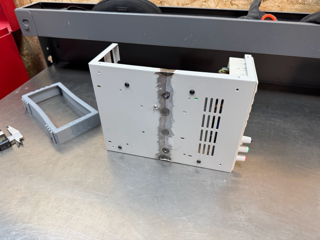
The official Riden case is designed to fit their largest bulk power supply, the 1440W that ships with the RD6024. The 240W Meanwell PSU is much smaller…
Let’s cut and shut it a little 🙂
What an impressive scar, Dr. Frankenstein would be proud. I tried to limit the heat input as much as possible but the thin steel still warped horribly, so I gave up after a few tack welds.
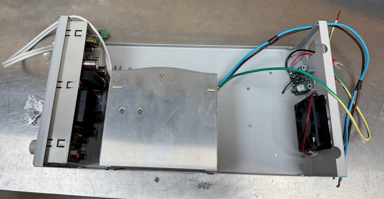
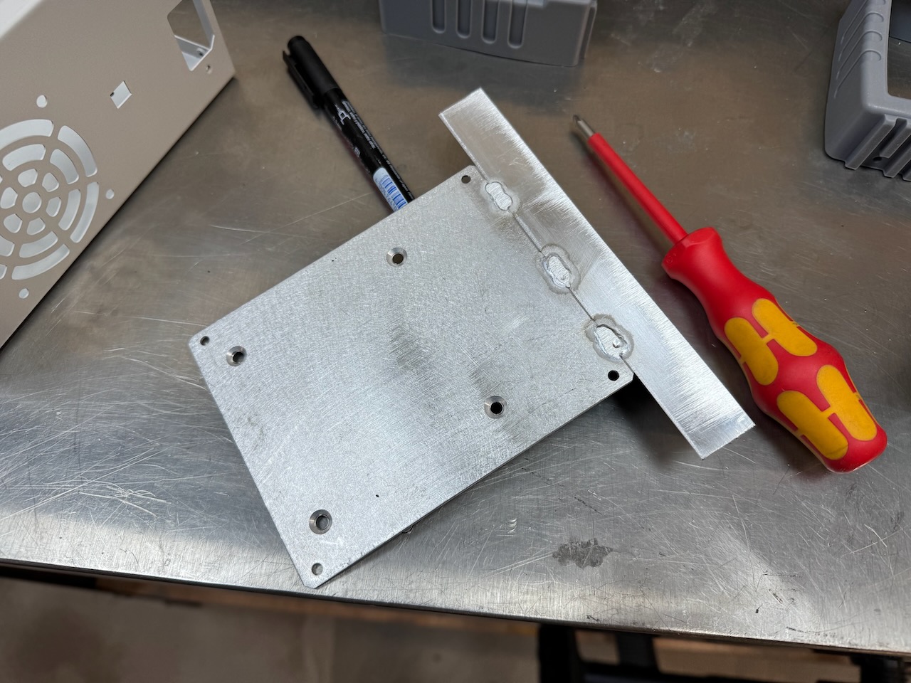
A bracket was made out of surplus aluminium sheet and angle to hold the PSU in place and handily also straighten out the warped casing a bit.
The Meanwell fits with room to spare, I think I could have cut the case even shorter.
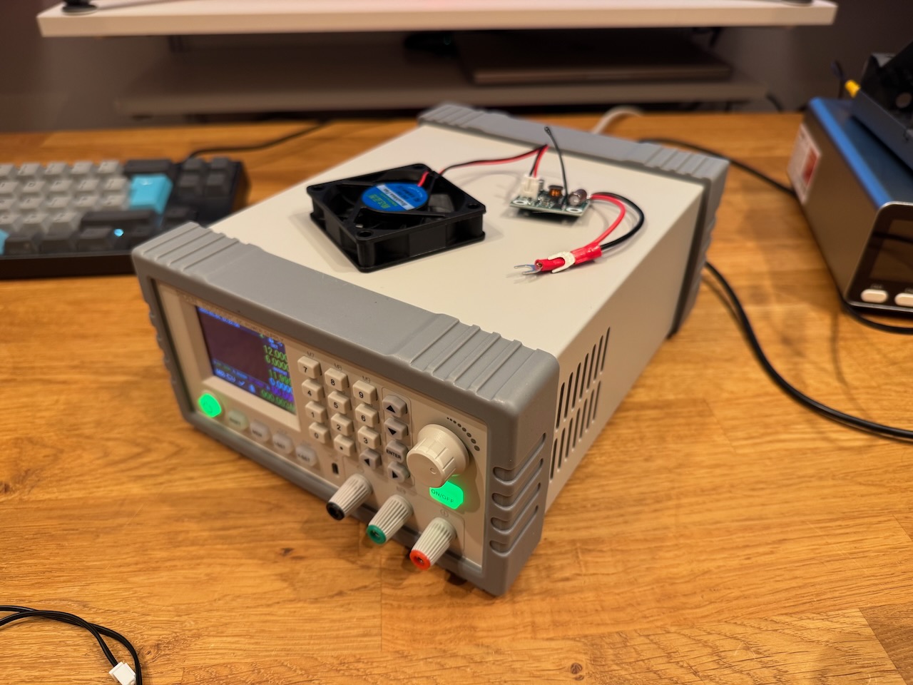
It worked, and I’ll install the fan kit another day 🙂
[In this episode of The Chinesium Mine we can’t resist the urge to dismantle the new power bank]
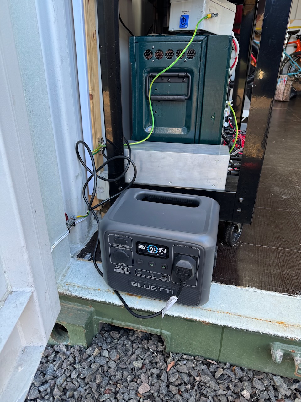
During my stay at Container Labs I got a Bluetti AC50B in the Black Friday sales. It was very useful as a kind of bucket of electricity that could be charged at home and used to recharge the main batteries on site.
I liked the Bluetti because it was cheap, used the safer LFP chemistry, and would accept a 230V AC input directly, unlike many other brands that need an external power brick to charge off mains. During my time at Container Labs it worked reliably and appeared to meet its advertised energy, power and runtime specs (700W, 448Wh) just fine.
As usual I couldn’t leave it alone and had to mess around with it.
AC UPS functionality
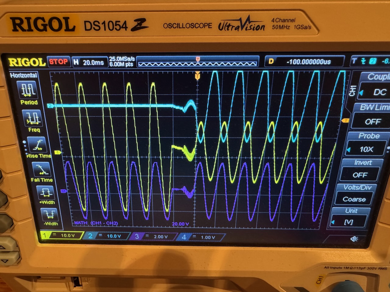
I checked out the behaviour when used as a UPS, by hooking up oscilloscope channels 1 and 2 to the live and neutral outputs from the front panel AC outlet, and connecting and disconnecting the mains input.
This scope shot tells us a lot about how the unit works inside. Even before taking it apart, we can see that it must use a bidirectional inverter/charger to transfer power between the AC side and the battery.
When AC mains is connected, it is passed through to the front panel outlet, and the inverter/charger charges the battery. The changeover of the front panel outlet from inverter to mains is seamless, as it synchronises to the mains frequency/phase before toggling the relay.
When the mains is disconnected, it quickly switches over to inverting mode. The switch back to inverter on loss of mains entails an interruption of about 20ms, a bit more than a dedicated UPS, but I’d be surprised if any load would be upset by this. I tried it several times and chose the worst looking transfer for my scope shot.
So overall it’s quite usable as a UPS. And they even used a double pole relay to change over both live and neutral. Some cheap UPSs only change over the live, and can feed voltage back into the neutral pin of the plug after it’s pulled out of the wall.
1 point for UPS functionality and not needing a power brick.
Other AC trivia
The output frequency is selectable as 50 or 60Hz in the Bluetti app. As I tested software in a previous life, I tried setting it to 60Hz before plugging it into our 50Hz mains. The unit wasn’t bothered, the frequency simply ramped down to 50 as part of the synchronisation process, and remained at 50 the next time mains was disconnected.
The power quality is decent, like most “true sine wave” inverters the waveform looks closer to a sine wave than the actual mains supply. (though again like most inverters, it’s easy to mess that nice waveform up with a nonlinear load)
With the inverter turned on but no load, the runtime displays as 41 hours. We can infer an idle power consumption of about 11W.
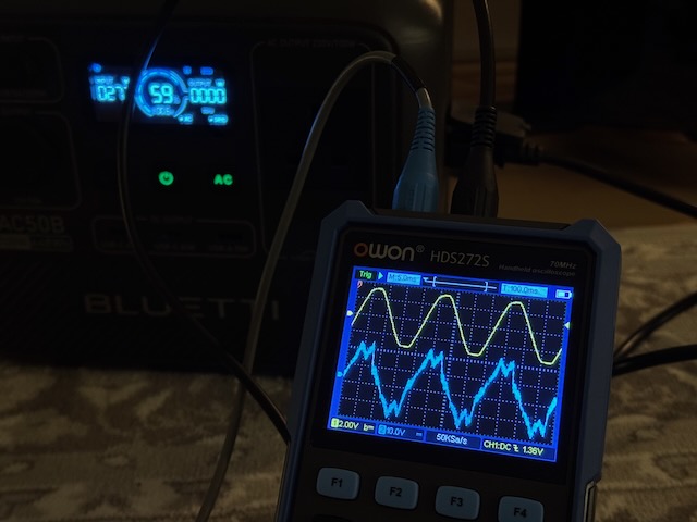
I also had a look at the current drawn from the mains when the unit is charging. Not the most sinusoidal, and a bit noisy, but it’s definitely making some kind of effort at power factor correction. (blue trace is current, yellow trace is mains voltage for reference, at 275W charging power)
Charging from the Lister diesel generator was also a success. It would drop out when a heavy load was removed from the generator, but always restarted.
Teardown
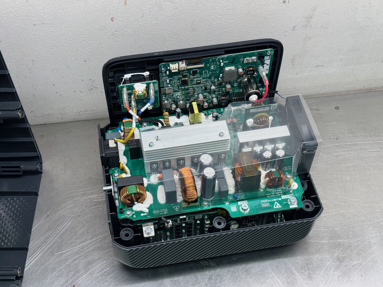
Next I took it apart. 1 point for not having any “warranty void if removed” stickers 😀
The build quality seems surprisingly good. The battery proper is in the bottom of the case. It looks like a bunch of large cylindrical cells.
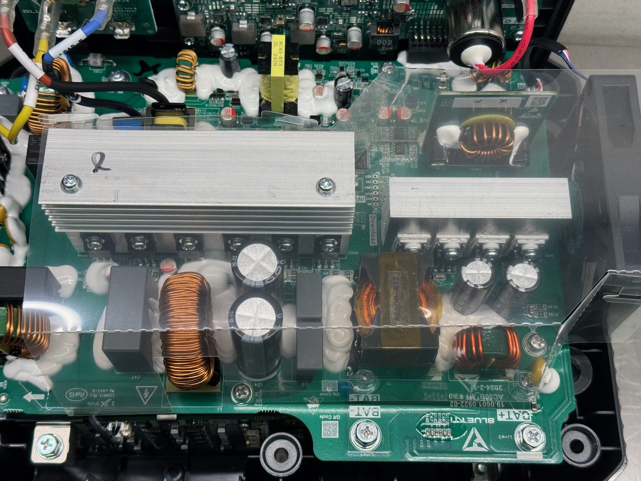
Most of the power electronics is on this PCB. Below the 2 large heatsinks we can see the circuitry for the inverter, which matches my earlier guess of a bidirectional inverter/charger.
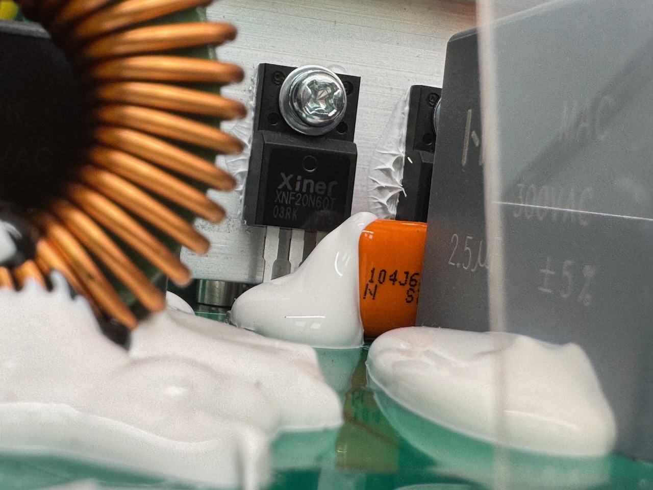
On the left heatsink we can see 6 XNF20N60T IGBTs from Shenzhen Invsemi. (£0.53 each if you buy 50.)
4 of these IGBTs function as the inverter H bridge when inverting, and rectify the incoming mains when charging. The remaining 2 function as diodes when the unit is inverting, to rectify the high frequency output of the DC-DC stage. When charging, these act as a half bridge driver.
On the right heatsink we can see a full bridge of 4 low voltage MOSFETs that drive the DC-DC stage when inverting. They must work as a rectifier when charging, but I didn’t figure out if they went to the extra hassle of synchronous rectification.
The DC-DC topology is probably a LLC with the inductance integrated in the transformer, and resonant capacitors on the secondary side.
I believe the vertical PCB above the MOSFET heatsink is the MPPT for the PV/DC input.
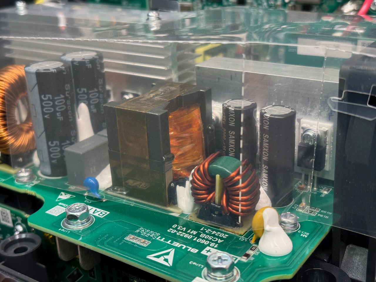
A better view of the DC-DC converter transformer. Our old friend triple insulated Litz wire is doing most of the work here as usual. I couldn’t make out a part number for the MOSFETs.
(It wouldn’t surprise me if there was another controller chip of some kind on the underside of the power board, but I didn’t dismantle that far.)
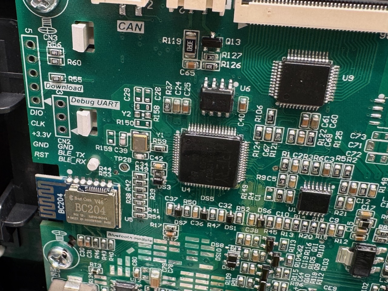
I was fairly sure everything in this unit would be Chinese, but Artery are actually Taiwanese. Their chips seem heavily inspired by the STM32.
Smart functionality
We can also see a Bluetooth module in this pic. The Bluetti smartphone app works fine, but there’s absolutely no security or pairing process. You just install on your phone and connect to any Bluetti within range.
Minus one point for cybersecurity. I’m sure if I took this to a seriously nerdy event like EMF it would be hacked and remotely self-destructed in 5 minutes. Todo: figure out how to add a switch that disables the Bluetooth.
Direct battery output?
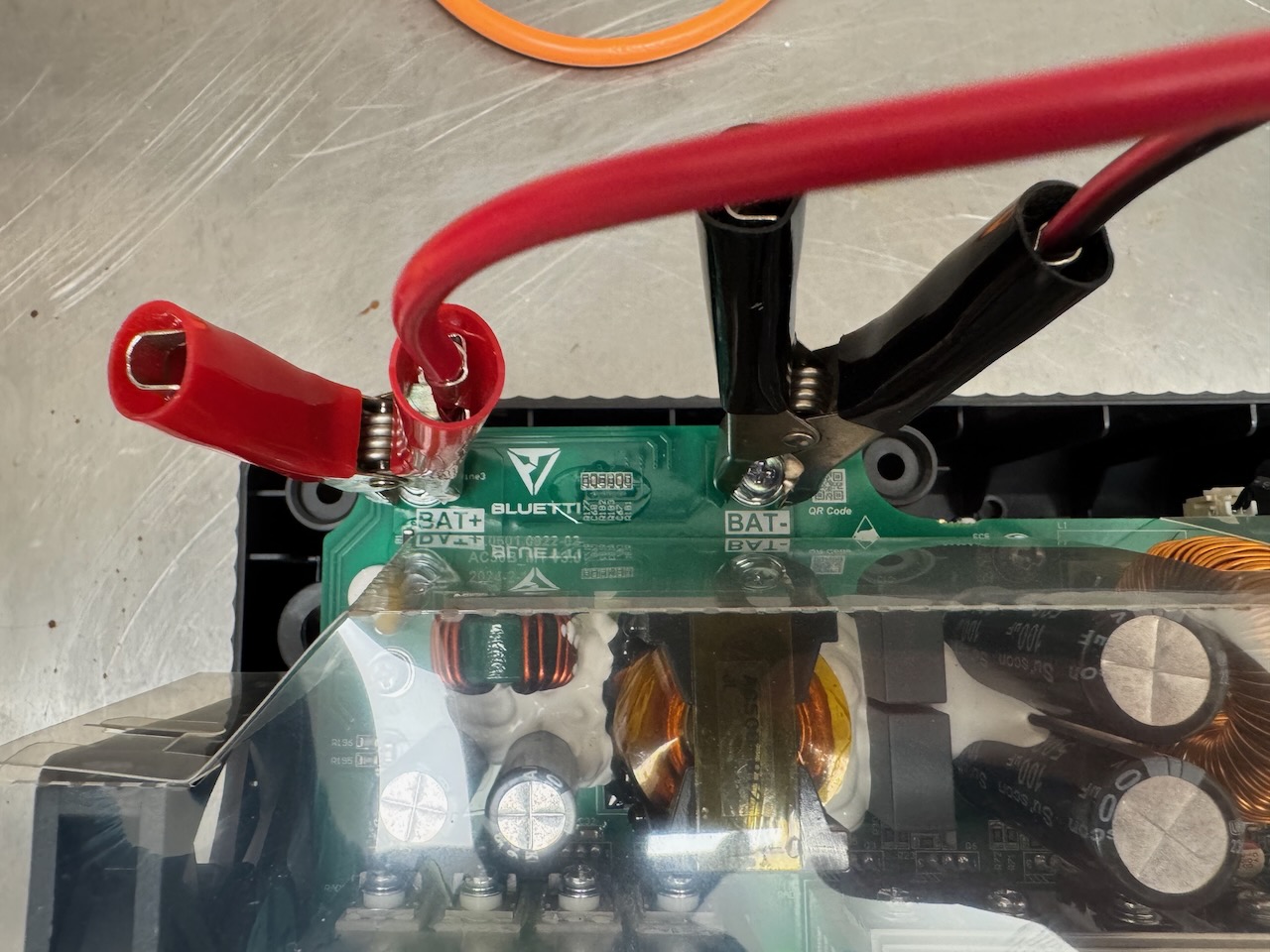
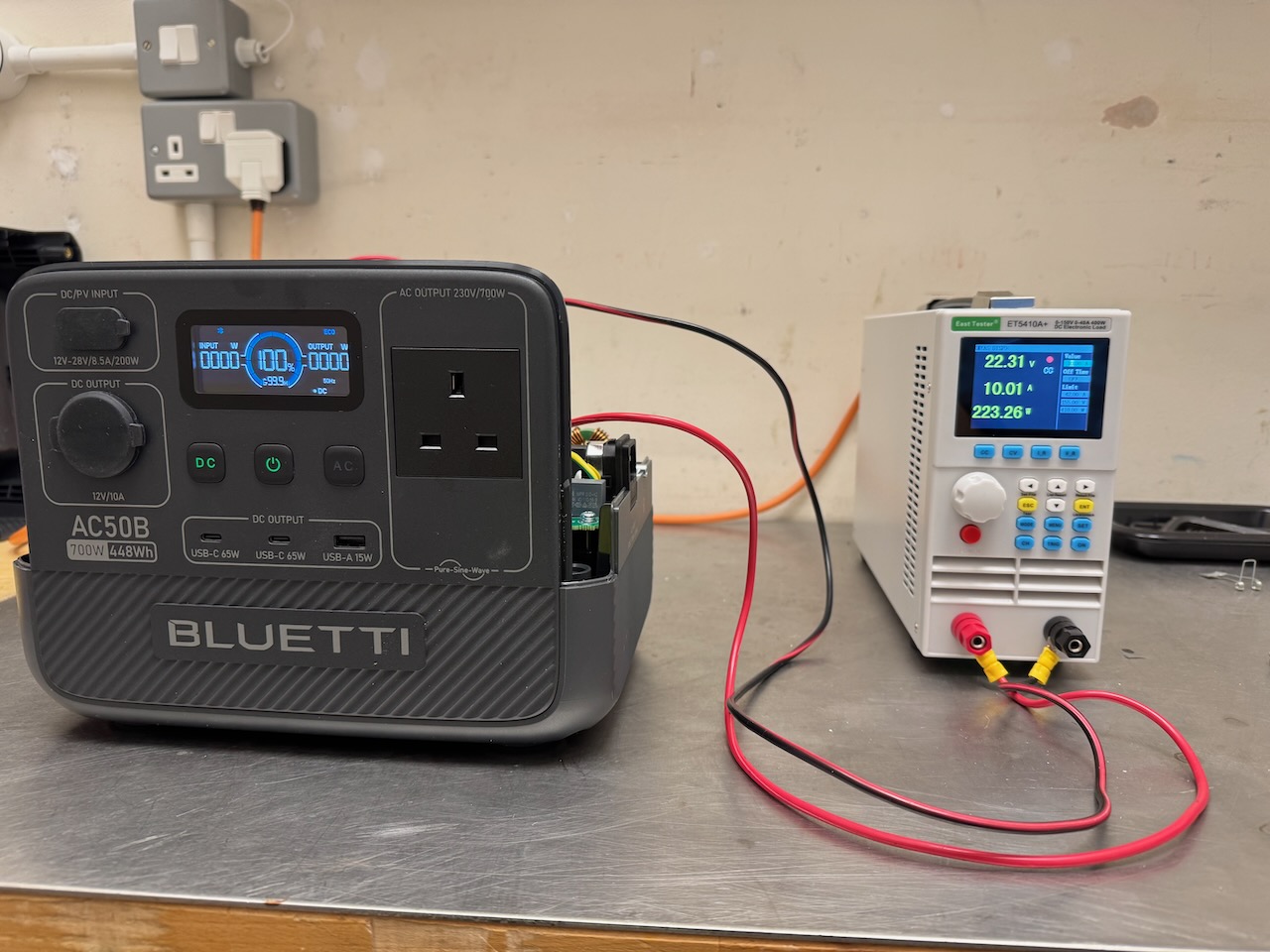
I couldn’t resist trying to draw power directly from those clearly marked BAT+ and BAT- terminals.
It worked, I was able to max out the electronic load and the Bluetti didn’t complain. At 22.3 volts, we can guess the battery must be 7 LFP cells in series.
The output power display showed 0 and the runtime remained at 99.9 hours the whole time, but the SOC display started to decrease. Half a point for “expandability” 🙂
Only half a point because I suspect something awful would happen if these terminals got shorted out or the battery was drained completely through them.
DC inputs and outputs
The DC/PV input is an XT60 connector. Bluetti supply two adaptor cables: a cigarette lighter plug, and a MC4. I tested it with 12 and 24V power supplies and it measured up to the rated 8.5A and 200W. I didn’t actually try it with a solar panel.
The 12V cigarette lighter output is 12.0V exactly and has pretty much no overload capacity. It trips off just above 10A even for short pulses. of current draw. This is to be expected considering that it’s derived from a 24V battery with a DC-DC converter, and I haven’t had any trouble with it in practice: the highest powered device I have that plugs into a cigarette lighter outlet is a 12V air compressor, and it ran that.
One point for comprehensive DC connectivity, and for not having any barrel jacks (aka DC5521)- arguably the worst DC power connector in the world!
DC UPS?
Would it work as a DC UPS to power Raspberry Pis and the like from the USB ports? I can’t say for sure that it doesn’t have some evil quirk that would stop this working, but I didn’t see any issues.
It can charge from AC or DC while powering DC loads. There is no float stage to the charging. The charger toggles on and off and the battery micro cycles between 98 and 100%. Or maybe it was 95 and 100%. Either way it seems like a reasonable charging algorithm, given that lithium batteries don’t like being held at high voltage indefinitely.
I also didn’t observe any overzealous auto shutdown of the DC outputs if the load didn’t draw current for a long time.
Conclusion
All in all, this is a perfectly good power bank. The only thing that leaves a slightly cheesy taste in my mouth is the “Power Lifting” feature, which is claimed to allow the unit to run appliances rated up to 1000W. It does this by simply letting the output voltage sag to about 200V under heavy load, so a resistive load that would draw 1000W at 230V only draws 700.
So as an engineer I feel cheated, but as a human being, I got coffee and porridge from this 1000 watt travel kettle (drawing 715W as you can see) Grudgingly then I give it an extra half point for the “Power Sagging” feature.
The final verdict: with 4 points this is
🀄️🀄️🀄️🀄️ Reactor grade Chinesium
A genuinely innovative product developed in China. The Chinese might not have invented the portable power station genre (that credit probably goes to the American founders of Goal Zero) but they surely have designed some nice units.
[In this episode of The Chinesium Mine we summon the ghost of Jim Williams to help reverse engineer some very bad frequency meters]
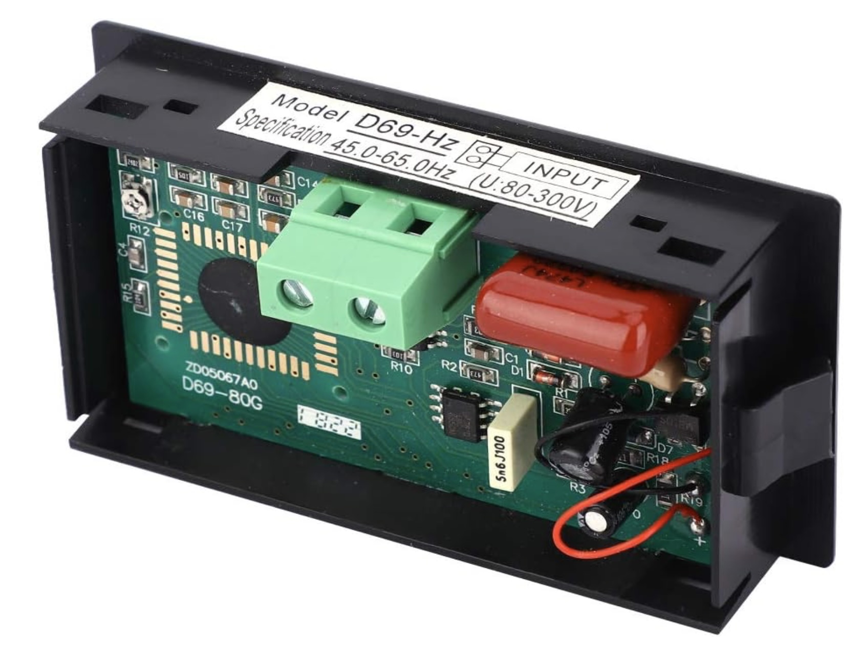
Back when I had the Lister diesel generator I spent some time looking for a frequency meter for it. I eventually settled on the “D69-Hz” digital panel meter from a questionable eBay store.
I bought 2 of these meters and was rather disappointed, both examples seemed very sensitive to temperature. And I wanted to use them to measure small changes in frequency in a location that sees big changes in temperature. Bother. The proverbial chocolate teapot (also useless because of excessive temperature sensitivity)
Out of curiosity I decided to dive a little deeper to figure out just why they were so bad.
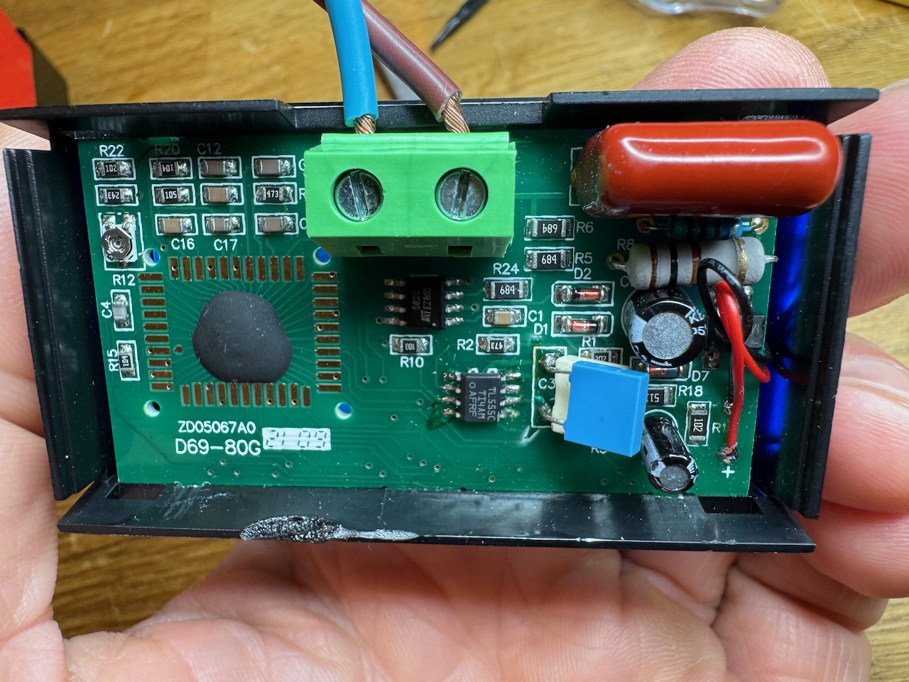
The obvious way to make a frequency meter is to use some kind of timer/counter algorithm to count cycles of the unknown frequency against a stable reference. But that was too obvious for our Chinese designers. This meter uses a frequency-to-voltage converter bolted onto the front of a digital voltmeter.
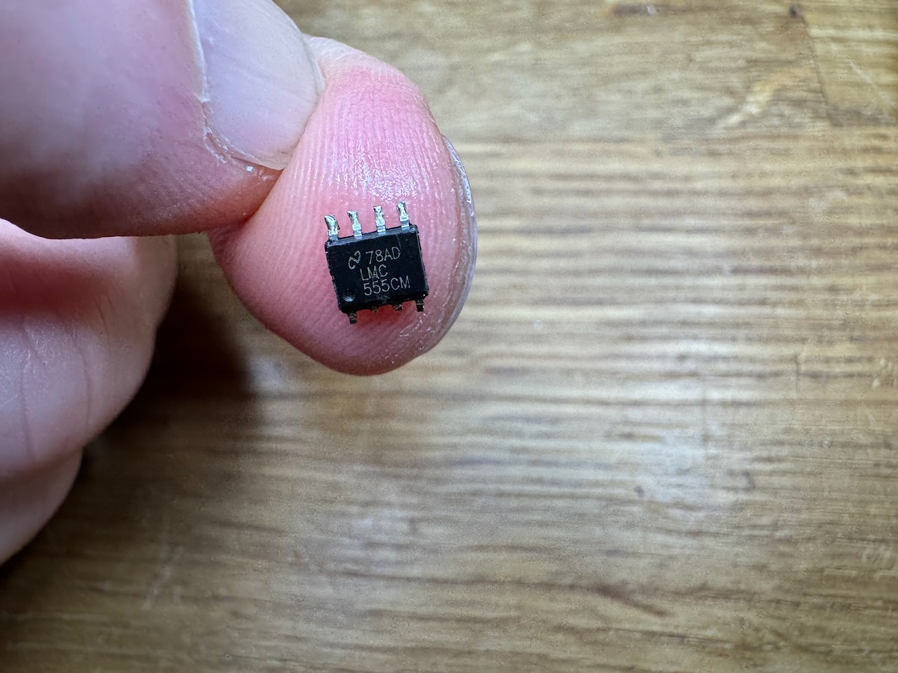
The F-V converter is a monostable made from a 555 timer chip, that generates a narrow pulse for each zero crossing of the input. These pulses are then averaged by the digital voltmeter chip. Everything runs off a single 3.3V rail, and the 555 timer used is of the CMOS variety, a LMC555.
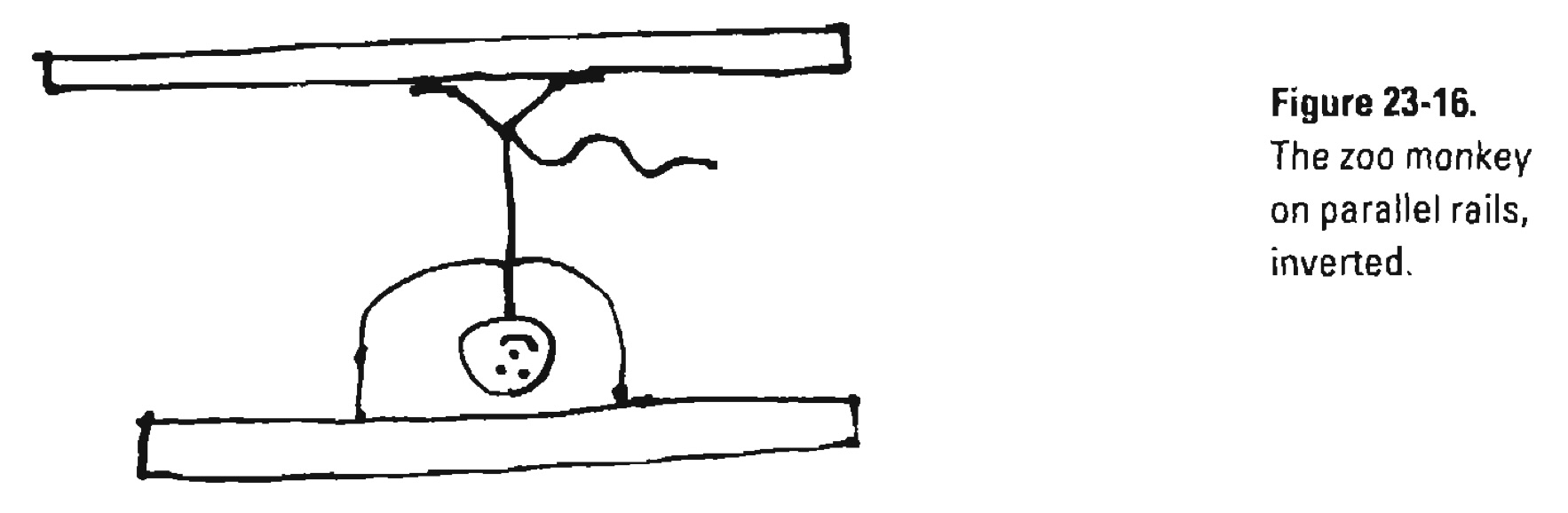
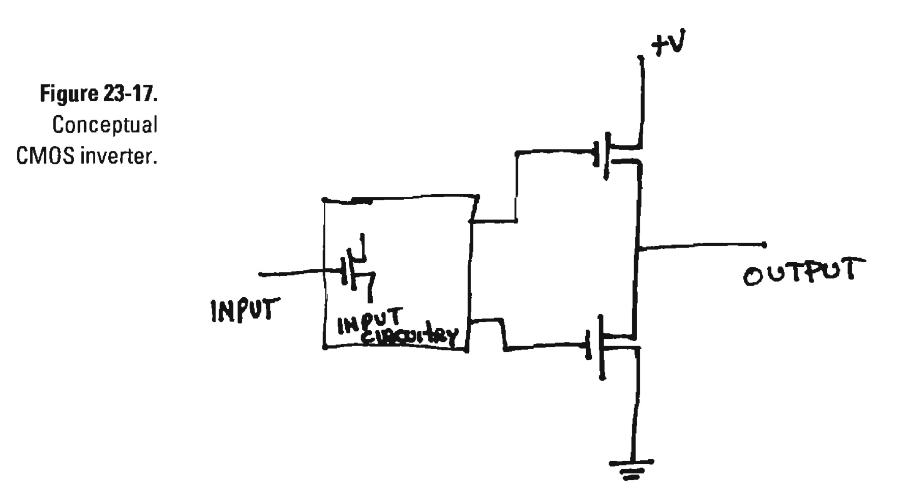
As the legendary, late Jim Williams explained in his writeup of the “zoo circuit” (see figures 23-16 to 23-18) the output stage of a CMOS digital IC is made of MOSFETs that switch cleanly from one supply rail to the other. There are no Vbe voltage drops like with bipolar transistors.
Williams was talking about a CMOS logic inverter chip, the 74C14, that he used to squeeze some more performance out of his “zoo circuit” V-F converter. But a CMOS 555 timer chip has the same output stage as a 74C14, and the designers of our Chinese F-V converter used CMOS here for the same reason: to eliminate the error due to the temperature dependency of those Vbe’s.
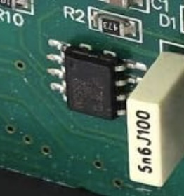
I scoped the output of my so-called “LMC555” and discovered that it was only putting out about 1.8V peak-peak with its 3.3V supply, and the output increased when the chip was warmed up.
Hah! a fake! A common or garden bipolar 555 timer remarked as a more expensive CMOS version. By far the most likely explanation for the missing 1.5V of output is two bipolar transistor junction voltages at 0.7V each. The 555 timer internal schematic on Wikipedia shows a Darlington pair for the high side of the output stage, so that would be our two Vbes right there. The low side is a common emitter, which would only drop a few hundred millivolts.
C3 is the monostable timing capacitor, I had to change it from 5.6nF to 3.2nF to reduce the pulse width in compensation for the increased output voltage of the new 555 chip.
Having done this, R12 was tweaked to read 50.0Hz with a mains frequency input at room temperature. Most Chinese meters I’ve seen so far have a “fortune trimmer” like R12 that can be twiddled to give almost any answer you want. I don’t think I even want to know the tolerance or tempco of this part.
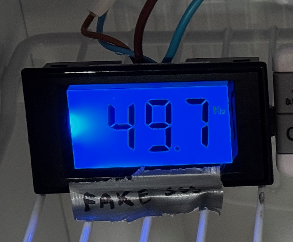
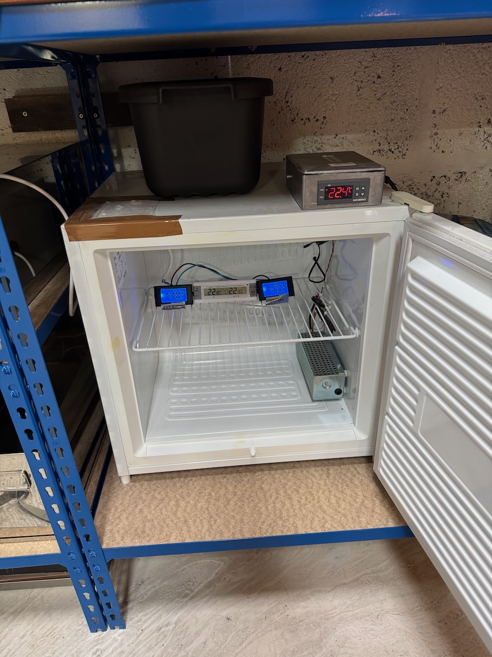
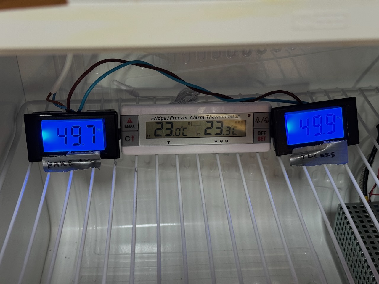
My modified D69-Hz seemed much more stable, so I put it in the Hayburn Labs environmental chamber alongside an unmodified one and a thermometer.
The environmental chamber is not a precision instrument (actually it’s a freezer from a charity shop) but it’s still incredibly useful for freezing and boiling prototype circuits to discover any temperature-related quirks before the customers do.
The mains frequency varied by more than I expected during this experiment, due to those meddling wind turbines. I had to go and look up the actual National Grid frequencies corresponding to the photo timestamps.
At 23C the meters read 49.7 and 49.9. National Grid official value was 50.111Hz so our modified meter is reading 0.211Hz low.
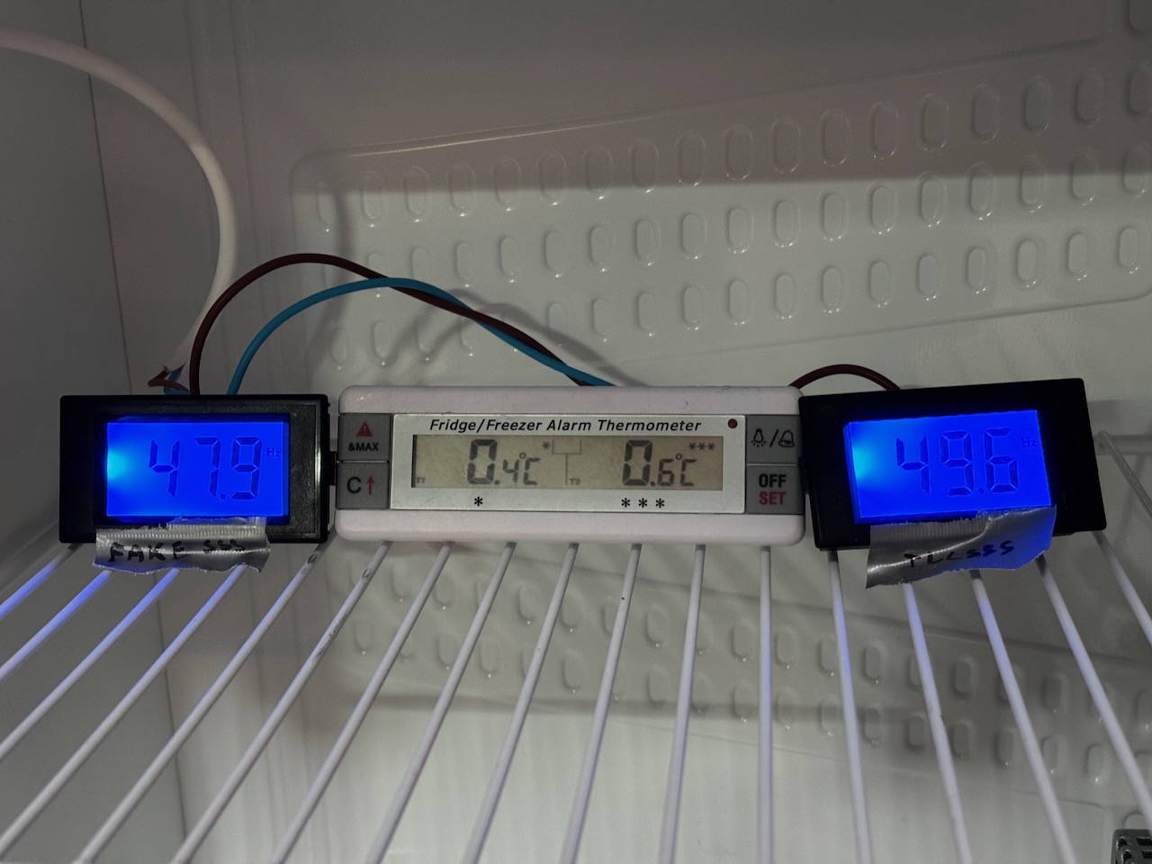
After refrigerating to 0C and allowing some time for temperature to equalise, the stock meter gave a reading of 47.9 and the modified one 49.6. Actual mains frequency was 50.041Hz so the modified meter has an error of -0.441Hz.
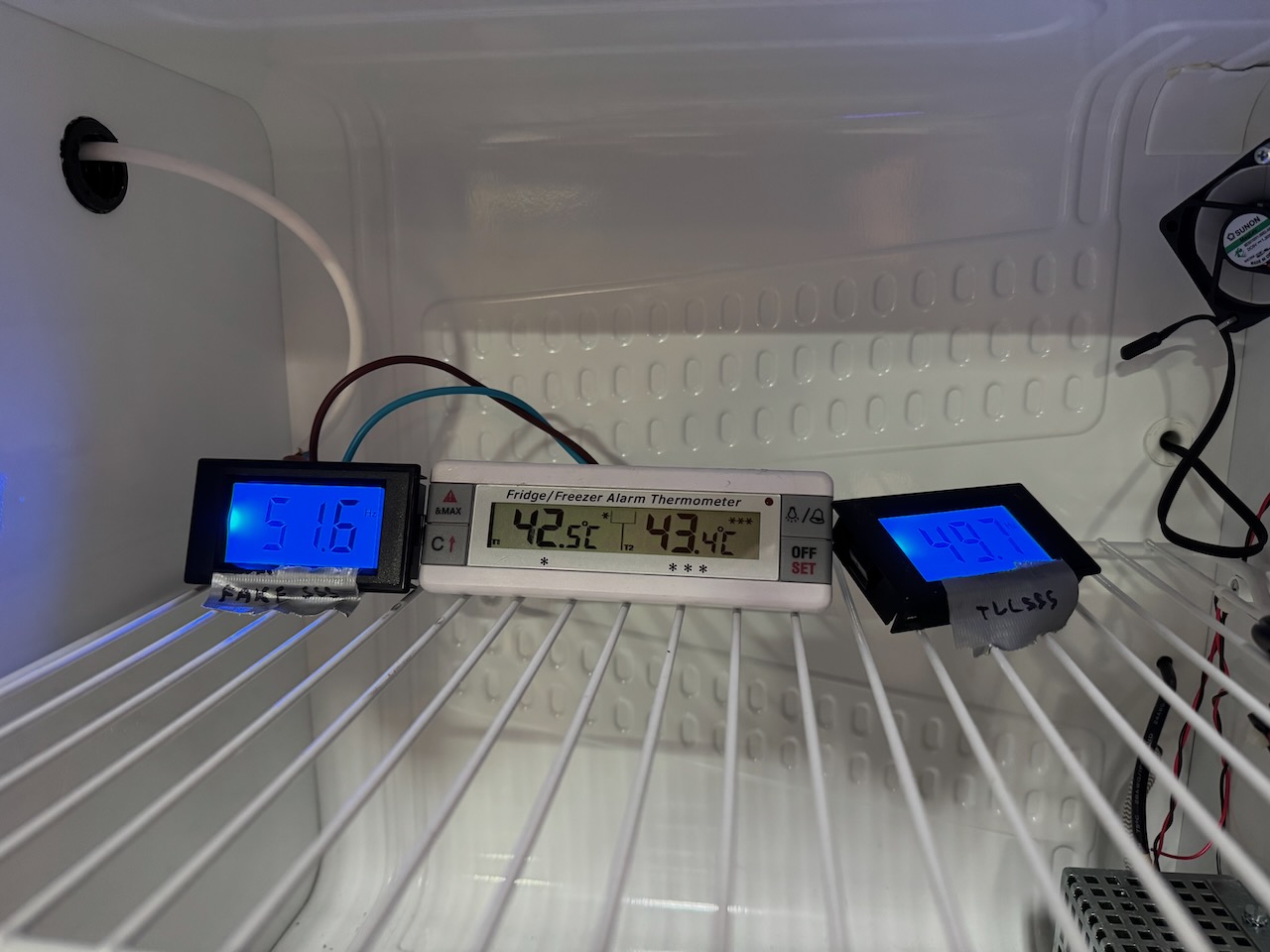
Stewing at 40C for 20 minutes produced a result of 51.6 for the fake 555 and 49.7 for the TLC555. Actual mains frequency was 49.881Hz so the modified meter error is -0.181Hz.
So over the 0-40C temperature range, we have an error of 3.7Hz (7.5%) for the unmodified meter and 0.26Hz (0.5%) for my modified one.
Conclusion: When I originally tested the Lister diesel, it gave a frequency of 51.25Hz unloaded and 50.00 on full load. And the temperature in Container Labs varied from below zero, to over 30C. The error with temperature of the unmodified meter would be more than twice the generator’s actual change of frequency, so it would have been completely useless.
By replacing the fake 555 chip, we reduced the temperature sensitivity by a factor of 15. But the error still works out as 20% of the frequency range covered by the Lister diesel.
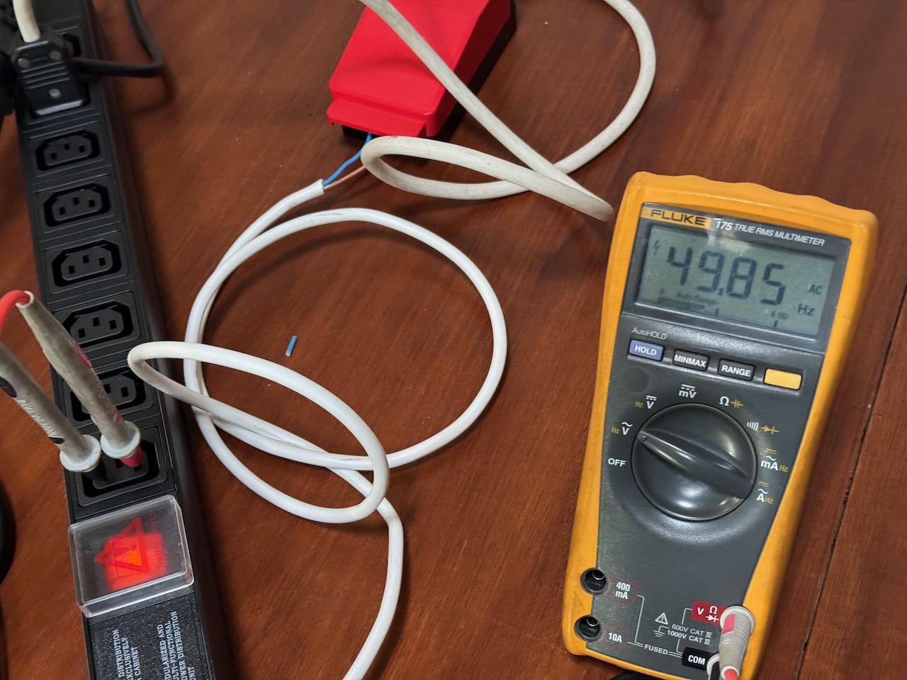
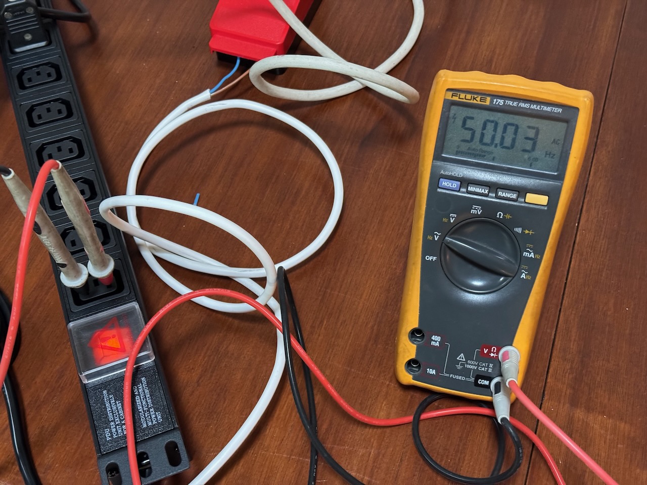
As a check I got out the same Fluke meter that I originally used to test the generator. It agrees with the National Grid website to within 0.01Hz.
(National Grid official value was 49.854)
(National Grid official value 50.034)
With this level of accuracy, I guess Fluke’s budget must have stretched to an actual quartz crystal in there somewhere, to give an accurate reference for a frequency counting algorithm. Our poor D69-Hz meters probably have a RC oscillator for the clock.
You can still buy the D69-Hz on Amazon, if you’d like a more laborious way of wasting money than simply setting fire to a £10 note. Believe it or not, I don’t earn a commission if you buy through this link. 😀
The 5.6nF capacitor and phoney “LMC555CM” are visible in the product photo, so I’m pretty sure it’s the same Shenzhen Chocolate Teapot Industries product.
[But it did. Extending your diesel heater control panel]
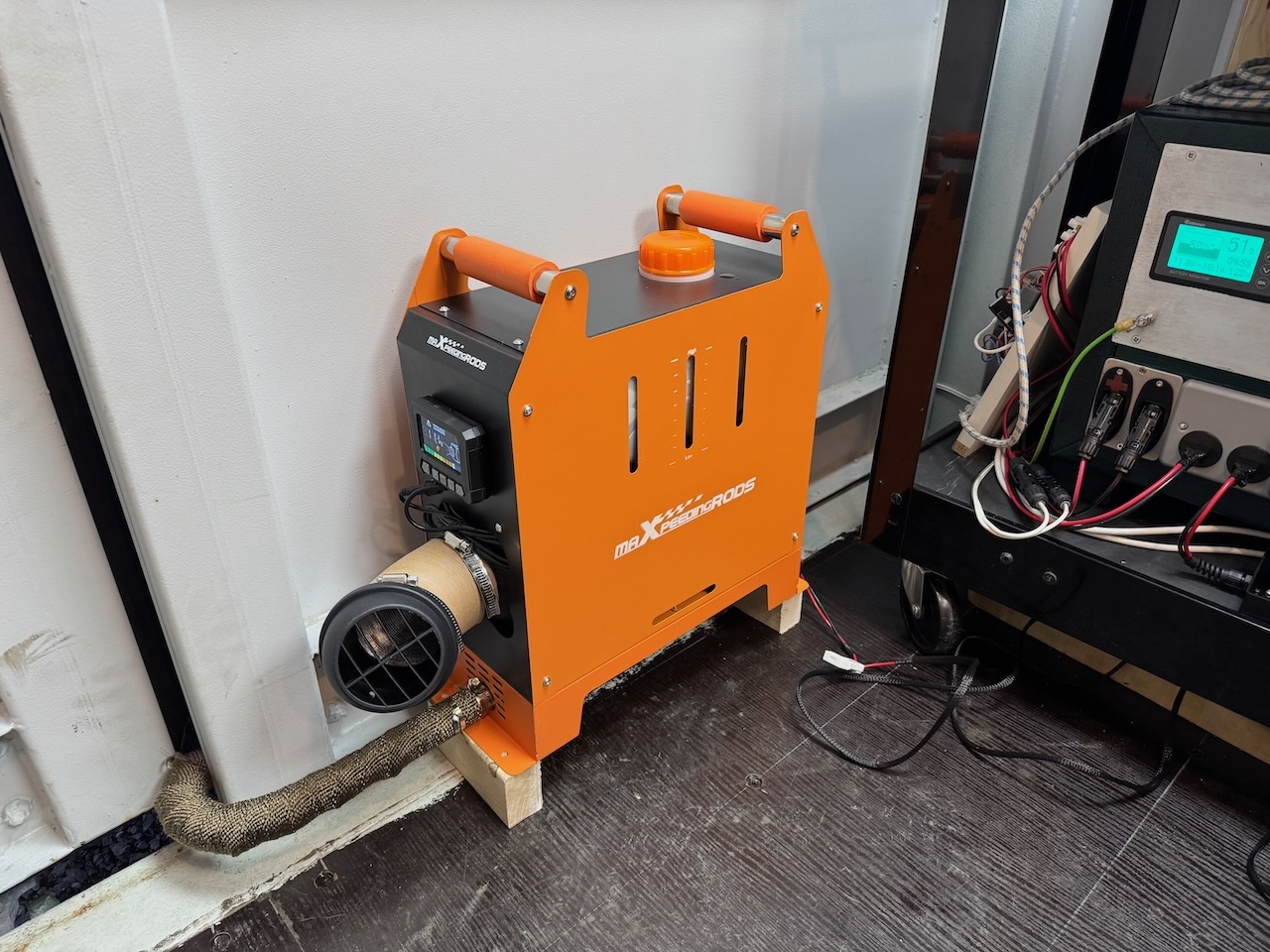
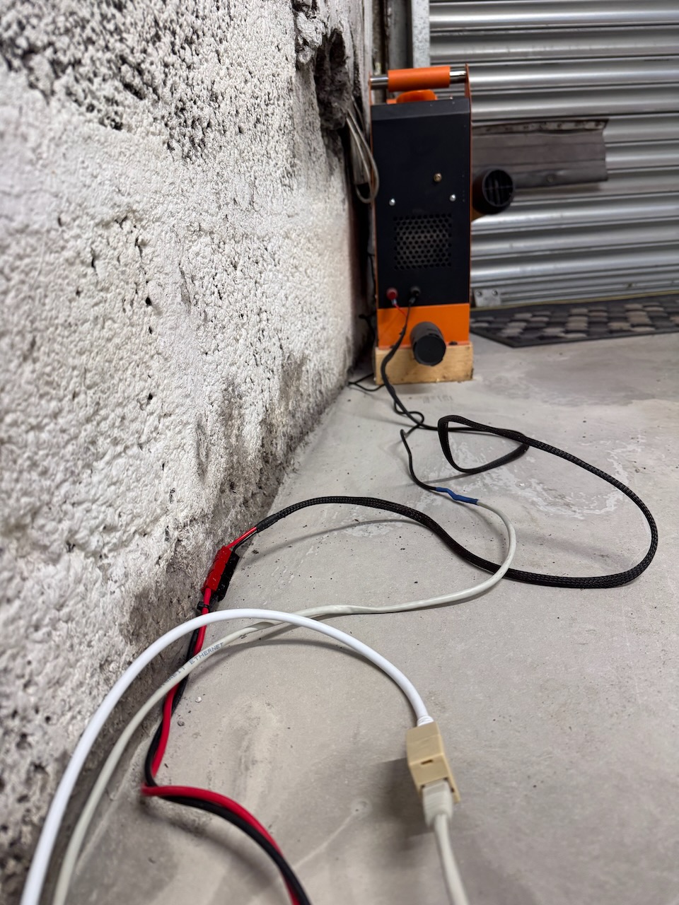
When I moved into Hayburn Labs, the diesel generator had to go, but my trusty (ish) MaxpeedingRods diesel heater came with me. I thought it was worth keeping as the running cost is about half of an electric heater.
There are dozens of brands of these devices, all Chinese clones of the Webasto air heater, priced at about one-fifth of the real thing. The real Webasto and Eberspacher heaters are sold as bare units for permanent installation in a vehicle, with the combustion air inlet and exhaust routed directly to the outside. But some Chinese entrepreneur came up with the idea of mounting the whole system together with its fuel tank into a portable box, with the combustion exhaust through a short length of pipe to nowhere in particular. This package proved quite popular and it’s now even possible to buy a European made version, the Autoterm Travel Box 2.
Mine must be one of the better clones as it hasn’t caught fire or gassed me with carbon monoxide. Yet.
For now combustion air is drawn from inside the building, and the exhaust pipe is poked through a hole in the wall. As I’m doing the place up (and making it more airtight) I plan to relocate the heater outside for safety, and it would be nice to extend the cable that connects the heater to the control panel. I haven’t seen much information about this online, so I’m documenting my experiments here.
According to the intertubes, all of these heaters have a 3 wire connection with a low-speed digital data link similar to the automotive LIN bus.
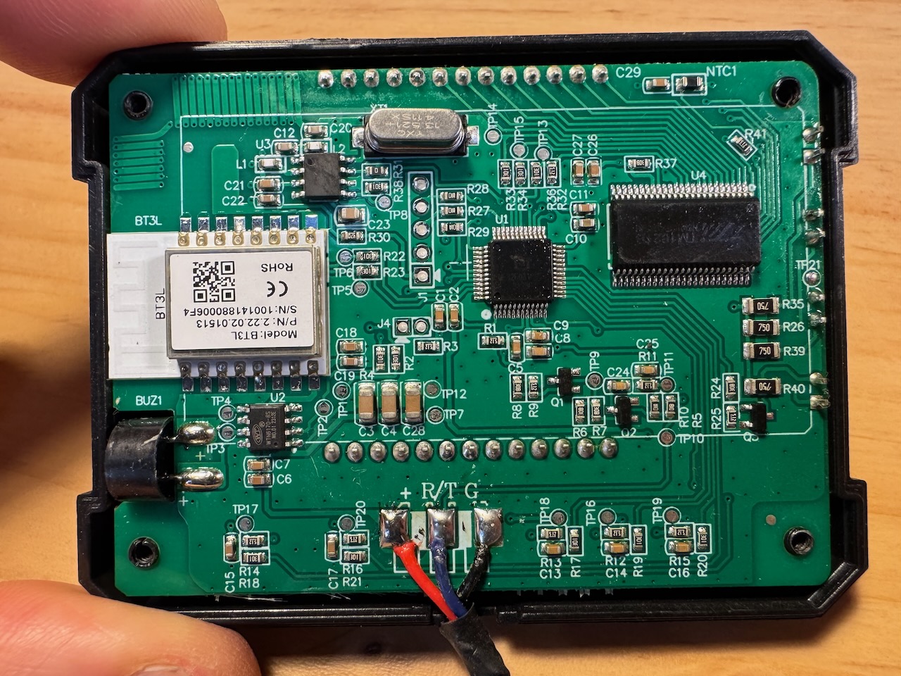
On opening the control panel, sure enough I found 3 wires marked +, R/T, and G, which I guess are positive supply, a bidirectional data line (Receive/Transmit?) and ground. Real LIN uses 12 or 24V for both power supply and signalling, but according to the manual, this is 3.3V. (yes it has a printed manual in legible English)
You can see from the PCB that it has both Bluetooth and 433MHz wireless remote functionality, and it came with a remote that works, so why am I even bothering to extend the wire? Well the temperature sensor for the thermostat functionality is on this board. Probably “NTC1” in the top right corner. So I think it makes sense for it to be in the main work area.
I unsoldered the three wires from the control panel PCBA, snipped a Cat5 patch cable in half and attached the two half-cables with the following colour code:
Signal name
MXR wire
Cat5 wire
+
Red
Orange, orange/white
R/T
Blue
Blue
G
Black
All other wires
As a Cat5 has 8 cores, I had 5 left over so I used several in parallel for the positive supply and ground. I thought this would help with voltage drop and noise pickup if it really does use 3.3V levels.
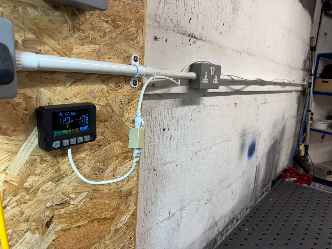
I plugged the two ends together with a RJ45 coupler, and the panel lit up and still seemed to work. So for my next test I interposed a 15m Cat6 Ethernet cable.
It still worked…
Discovering what happens when the control panel is unplugged with the heater running is an exercise for the reader. A reputable manufacturer like Webasto would of course have tested this and made sure it went through its normal cool-down and shutdown sequence. I wonder if the Chinese clone makers have that much attention to detail.
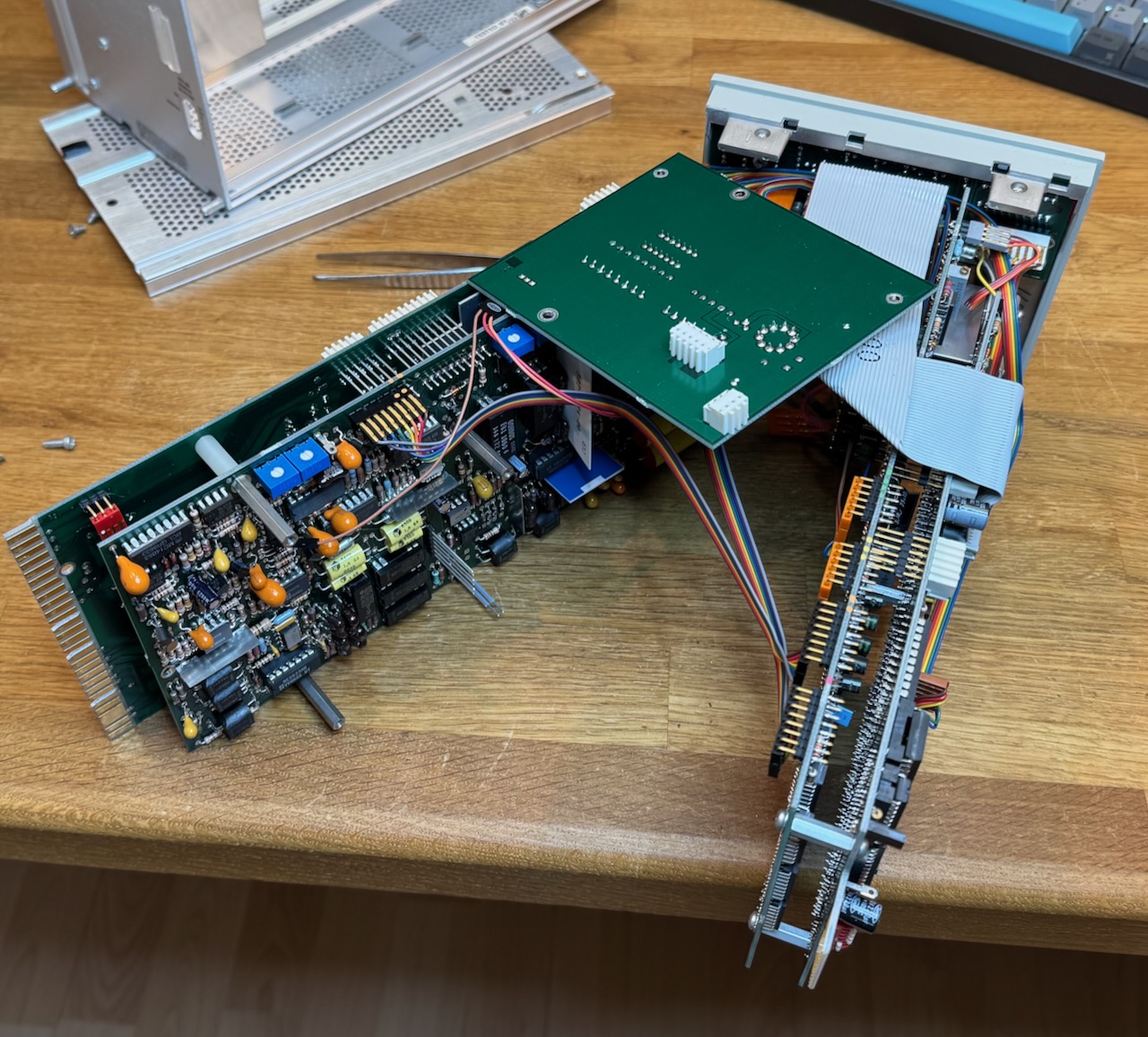
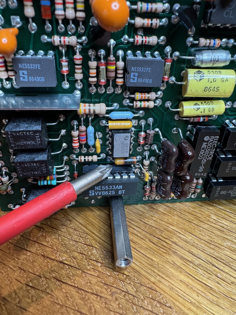
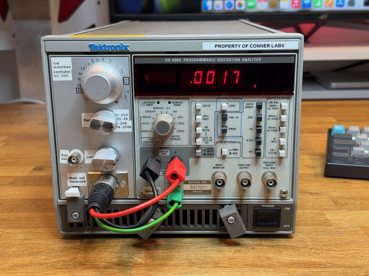
I’ve been doing a bit of work on audio amps lately, so it was a bit annoying when my Tektronix distortion analyser suddenly died.
With a very distinctive smell. I try to avoid using tantalum capacitors in my own designs, so it was one I hadn’t smelt in a while. The older tantalum beads were somewhat unreliable, with a tendency to fail short circuit, crack open and spew their metallic innards in a way that always reminded me of the egg from the first Alien movie.
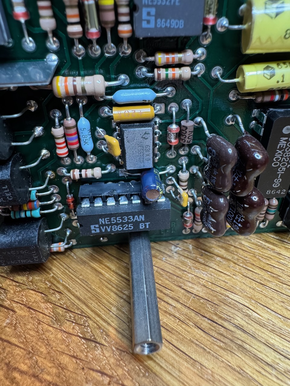
The innards of the DA4084 are a sandwich of multiple circuit boards connected by random wires, and a bit fiddly to dismantle. And of course the obviously burnt tantalum capacitor was right in the middle of the sandwich.
I guessed it was used for decoupling and the value wouldn’t be critical, so I replaced it with a 10uF electrolytic.
In 2011 I built the Selfless Amp, my first hifi power amp designed from scratch, albeit very strongly influenced by Douglas Self.
I also used it as an opportunity to try the then-new ThermalTrak power transistors from OnSemi. These have a temperature sensing diode co-packaged with the transistor, which promised to eliminate all biasing hassles.
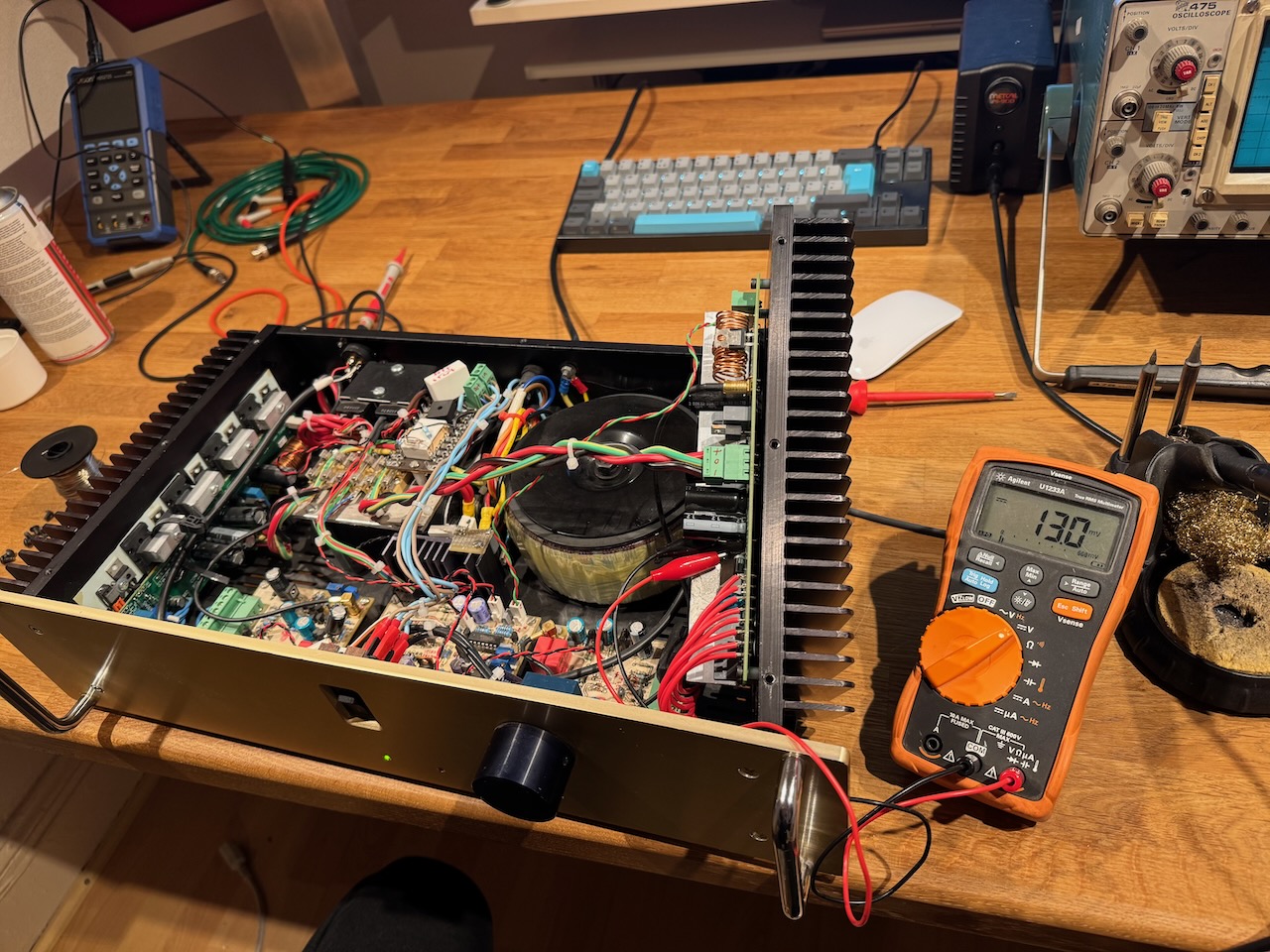
More recently I noticed the right channel heatsink was getting a lot hotter than the left channel. The problem would come and go, and a few times I reset the bias only for it to become too cold later.
I ran it for ages like this but eventually got the time and inclination to get to the bottom of the issue. Prodding the circuitry with a stick and bending the circuit boards made no difference, so loose connections were ruled out. And the fault followed the output stage board when parts were swapped between channels. Therefore it was most likely either in the driver transistors, bias generator transistor, or one of the output devices.
Connecting a scope in roll mode across one of the emitter resistors, I could see the quiescent current jumping around at random.
I tried replacing the driver and bias generator transistors (Q1 and Q3 in this schematic) but it made absolutely no difference. At this point I also noticed that the jumps in quiescent current could be seen across all of the emitter resistors. If the problem was in an output transistor, I’d expect it to only affect a single device.
This pretty much narrowed it down to an issue with the ThermalTrak diodes, so my next move was to replace Q4 and Q5, the pair of output devices whose diodes are used for bias generation.
Stability was restored.
I have seen faults like this in the past where semiconductor junctions would develop temperature sensitive behaviour over and above the usual -2 millivolt per kelvin. The late Bob Pease wrote about a batch of diodes he came across that acted as thermostats, going open circuit above a certain temperature. This seems to be a less extreme version of the same thing, where the forward voltage of the ThermalTrak diode jumps around at random by 10s of millivolts as the temperature ramps up. I’m an applications guy, not devices, so I don’t know the semiconductor physics behind it. My guess would be bad packaging putting a temperature dependent mechanical strain on the device.
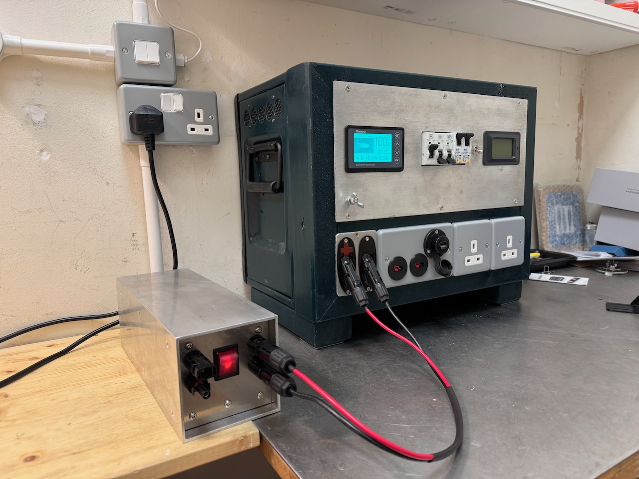
The Power Tank uses a Victron MPPT 75/15 for battery charging. I experimented with this and found that it would happily charge from a DC power supply connected to the PV input.
I tried several different bench power supplies and also 18V DeWalt cordless drill batteries, and all seemed to work fine. Victron specify that the DC input voltage has to be at least 5V above battery voltage for the charger to start, and then 1V greater for it to continue running, so in practice 24 or 48V DC would be a good input voltage for my 12V system.
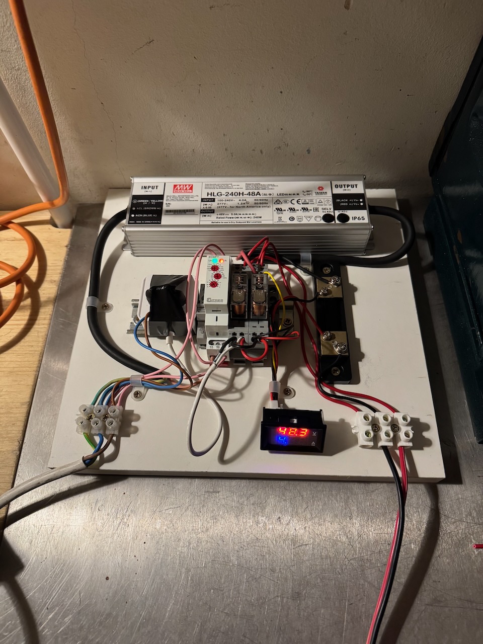
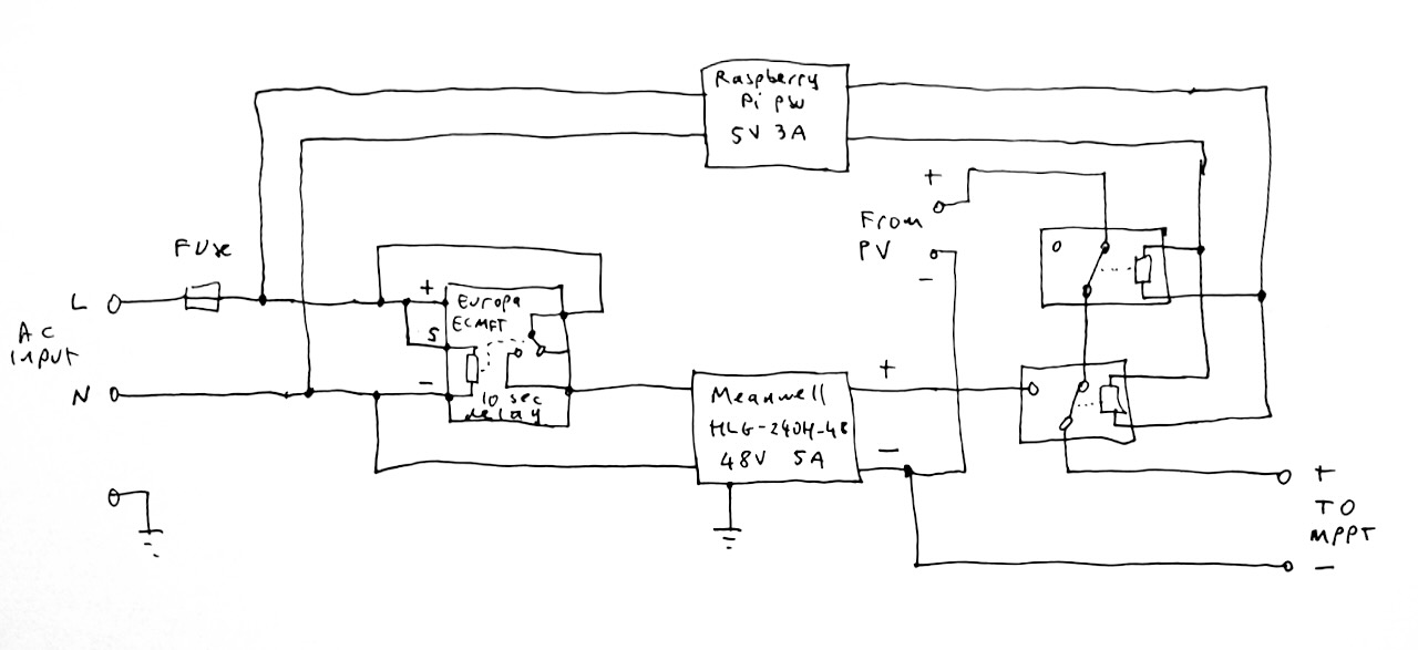
I settled on a Meanwell HLG-240H-48A LED driver obtained cheaply on eBay, that supplies 48V DC at 5A.
This worked just fine plugged directly into the solar input, but I decided to complicate things by adding an automatic changeover between solar and AC charging when AC power was present. My first attempt was to use a couple of diodes to OR the solar and PSU inputs, but this didn’t work. The PSU would be dragged into current limit as soon as it was turned on, and the MPPT would then ramp its output voltage up and down searching for a max power point and never find it.
The key to a successful changeover turned out to be to disconnect the solar panels, wait 5-10 seconds for the input voltage to fall to zero and the MPPT to shut down, and then connect the power supply. I made a circuit to do this automatically depending on the presence of AC power.
This junk box inspired design is based on a Europa ECMFT timer relay, and a Raspberry Pi 4 wall power supply that I’d previously cut the DC plug off for some reason. When AC power becomes present, the Raspberry Pi wall wart supplies 5V to a changeover relay, that disconnects the MPPT positive input from the solar panels and connects it to the 48V DC PSU, which is still turned off. After 10 seconds the timer relay switches the PSU on.
When AC power is lost the reverse happens. The 48V PSU turns off straight away, while the Raspberry Pi PSU keeps the changeover relay energised for a few seconds on its stored energy. This avoids the changeover relay having to break the 48V while current is flowing.
The main weakness of this circuit is that it uses a relay to break and make the DC output of the solar panels. Relay contacts typically have much reduced DC ratings compared to their AC rating, and most won’t even handle more than 30V DC.
This isn’t a huge problem, if there was lots of solar power available, why would I even be switching over to AC charging? Also my solar array is tiny and puts out less than 30V DC. However, I paid it some lip service by choosing a relay with a 30V DC rating, and putting two of them in series on the PV side. (What if the 2 relays don’t open at exactly the same time I hear you ask? Next question please…)
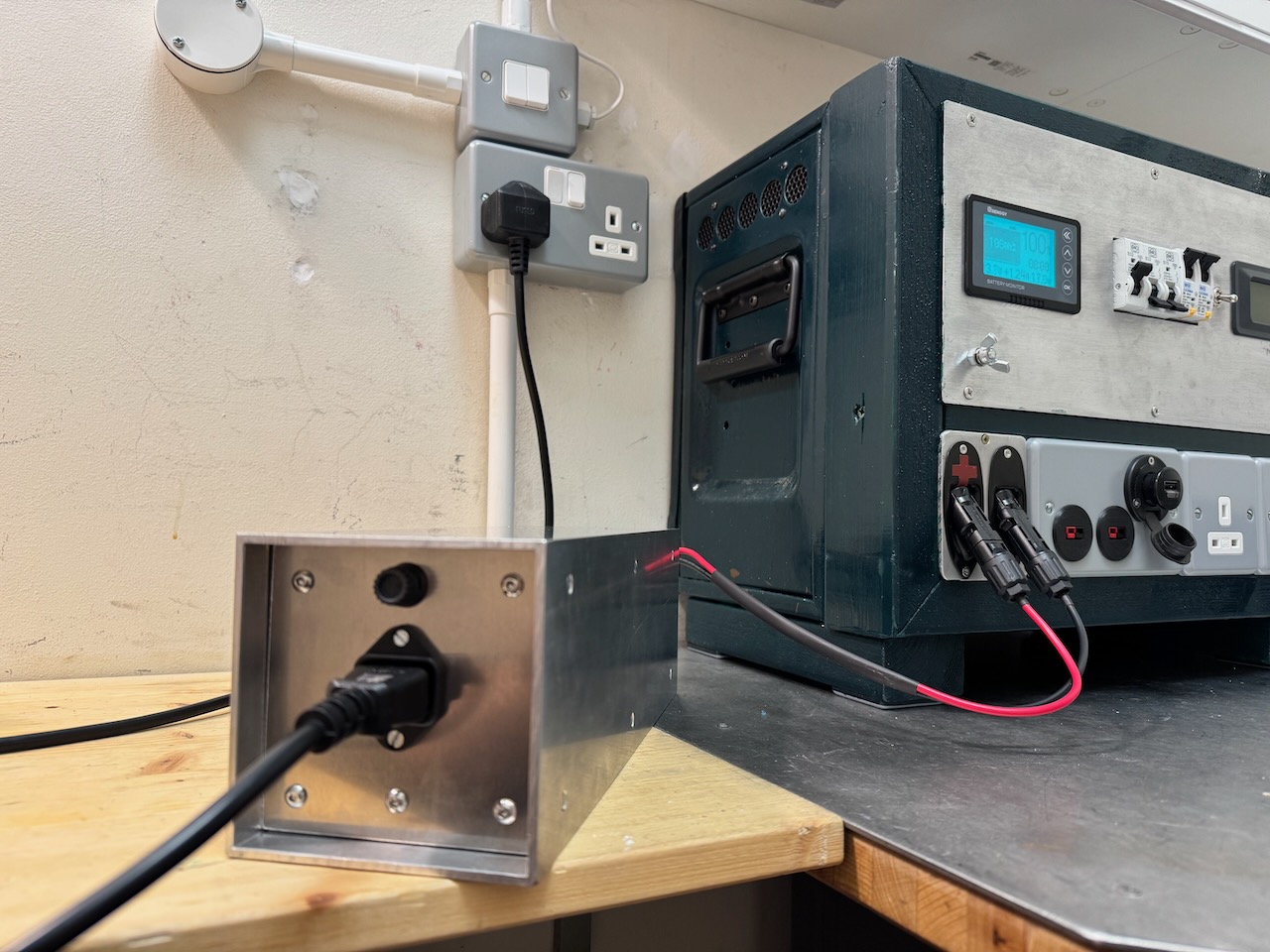
I tried a new enclosure construction technique for this, based on a piece of 4″ x 4″ aluminium box section. The ends are made of sheet aluminium and attached to the box section by aluminium angle. The HLG-240H-48A is screwed to the case with a generous amount of heatsink compound to help it lose heat by conduction, which it seems to manage OK.
You might notice that the prototype had a digital voltage and current meter which is now gone. This cheap Chinese meter turned out to be basically a random number generator so I ditched it.
I think it looks great, but the wiring was a real pain and ended up very messy inside, because it all had to be done through the ends. I’m not sure I’d use this technique again unless the innards could be made to slide out as a single unit. That wasn’t possible in this case because of the power supply covered in heatsink grease.