Tesla Model 3 heater testing

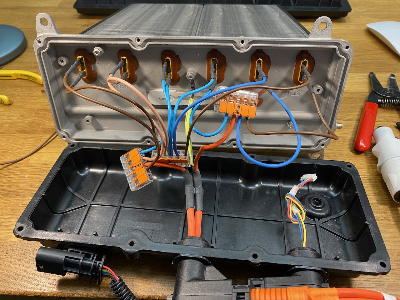
I thought I’d better test the characteristics of the PTC elements in a scientific manner as opposed to just applying 750V DC from the PFC and seeing what happens.

When measured with a multimeter at room temperature, each element read about 600 ohms. This would imply a rather low power output if that was the minimum resistance.

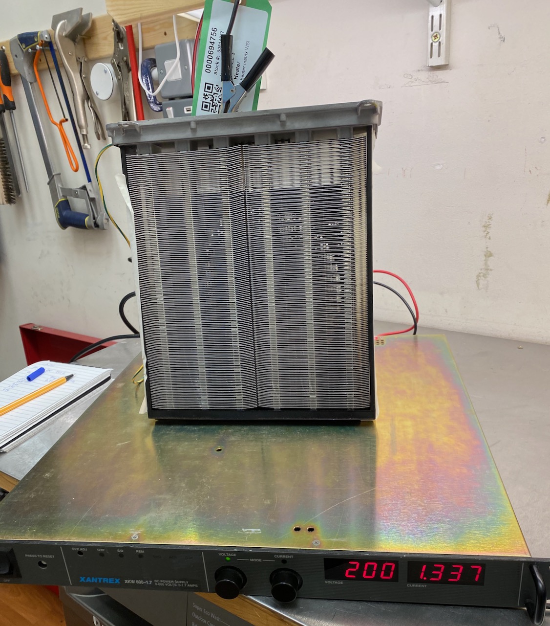
For my next experiment I connected one of the elements to my old Xantrex 600V bench power supply. The 600 ohm cold resistance would imply a draw of no more than 1A at 600V if the element was purely PTC. But to my surprise, the current draw actually began to increase as the element got hotter, eventually hitting the PSU’s 1.7A current limit at only 200V.

This means that the elements must actually start off as NTC, and transition to PTC at a higher temperature. That kind of makes sense, as a car heater matrix has to be able to start up from very low temperatures. Purely PTC elements would presumably exhibit an immense current surge when the heater is turned on after leaving the car parked overnight in Canada. πŸ™‚

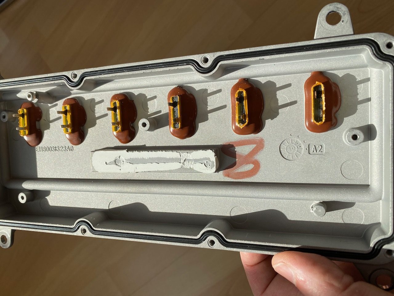
I was wondering why Tesla bothered to implement individual control of the 6 elements, and I guess the turn-on surge is the answer to this too: by turning them on sequentially the surge can be made 6x smaller. It’s not like a Tesla traction battery (or even an IGBT) would care if the turn-on surge was 10A or 60, but maybe it allows them to use a lower rated fuse to connect the heater to the battery. Fuses rated for high voltage DC are expensive so the savings made here might outweigh the cost of 5 IGBTs and drivers.

Anyway, I couldn’t test above 200V due to the limited output current. The next larger PSU I have is the PFC, and it has a minimum output voltage of 400V (600 on 3 phase) so I will just have to “send it” as the kids say nowadays.

Tesla Model 3 cabin heater teardown

I needed a high power dummy load that was a bit more health and safety friendly than my bucket of immersion heaters. I investigated lots of possibilities until I eventually found a Tesla Model 3 heater matrix on eBay. The Internet said it could draw up to 6kW, and being PTC, it shouldn’t catch fire if I forget to turn the fan on, which would look great on a risk assessment. So I went for it. πŸ™‚

The lid is held on by penta-lobe screws with a tamper-proof peg in the middle. There was nothing in my collection of tamper-proof bits that would fit, but a sturdy flat-bladed screwdriver worked quite well after Dremeling a new slot or just jamming it in hard enough to break off the peg. πŸ˜€

Ooh, fancy! What does all this stuff even do?

There appear to be 6 separate PTC elements, each with low side switching by a 600V IGBT and non-isolated gate driver.

To the left of the IGBTs is a voltage divider and low side current shunt, and on the right an isolated CAN interface and DC-DC converter. Handling CAN communications and A/D conversion of the voltage and current signals, we have an 8 bit ST microcontroller (probably sharing its 0V rail with DC bus negative)

Of course I immediately set to work reverse engineering the CAN protocol so I could command it to connect its elements in 2 groups of 3 for 800V input. Oh wait that’s not gonna work πŸ™ we need a hardware solution…

The heating elements were connected to the PCB by spring clips that released quite easily, but the PCB was stuck firmly to the aluminium enclosure with thermally conductive glue. I freed it with the old embedded programming trick of heating the enclosure with a heat gun and prying with a paint scraper. (sadly this doesn’t work any more in Python 3 πŸ˜‰ )

With the PCB removed we can see the terminals for the heating elements, looks as if some sort of spade terminal should fit nicely. (Also note the little nodule at bottom right which appears to be for cooling the CAN transceiver chip.)

And after a pulsating second half the score is Wago 221, CANbus 0. πŸ˜€