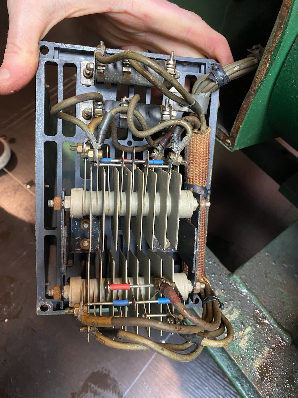
After a period of working OK Lister’s output voltage began to sag horribly under load. The selenium rectifiers are known to be unreliable so I decided to replace them.
The below schematic shows how the Brush 3kVA alternator is wired (Brush connection diagram 9840322)
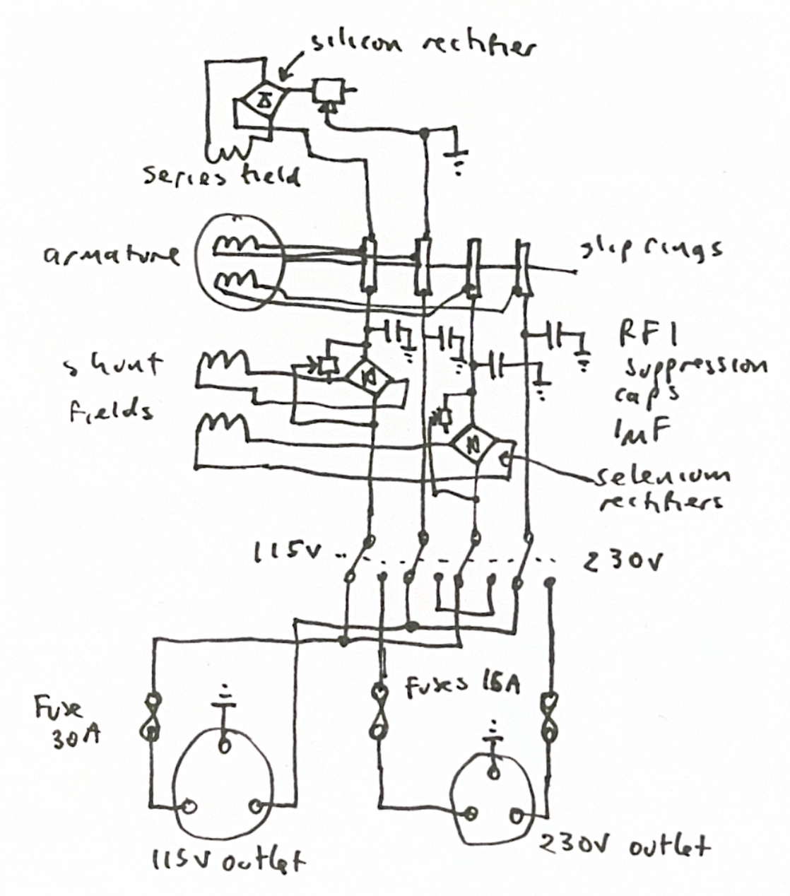
The generator has both shunt and series fields. A silicon bridge rectifier provides excitation for the shunt field while the series fields are energised by a portion of the load current, through the selenium rectifiers. The armature and series fields are in two identical sections that can be switched in parallel for 115V or in series for 230.
Note that in 230V mode the output is centre tapped to earth. Both live and neutral pins of the outlet have 120V on them. This seems to be a design decision by Brush to reduce the risk of electric shock, however it means that live and neutral both need to be fused.
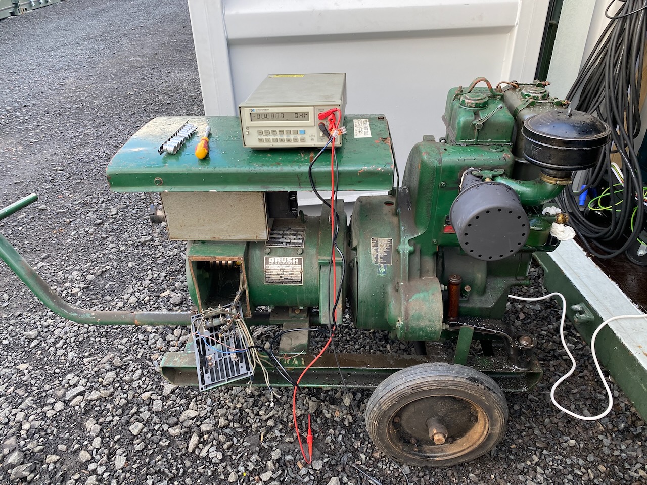
I took the opportunity to do some 4 wire resistance measurements while the wiring was disconnected. One section had a series field resistance of 0.20 ohms and a diverter resistance of 1.00 ohms. The other had a field DCR of 0.21 and the diverter resistor was set to 0.87. This resistor was burnt from a previous short circuit so I cleaned it and reset to 0.96 ohms using the unburnt end.
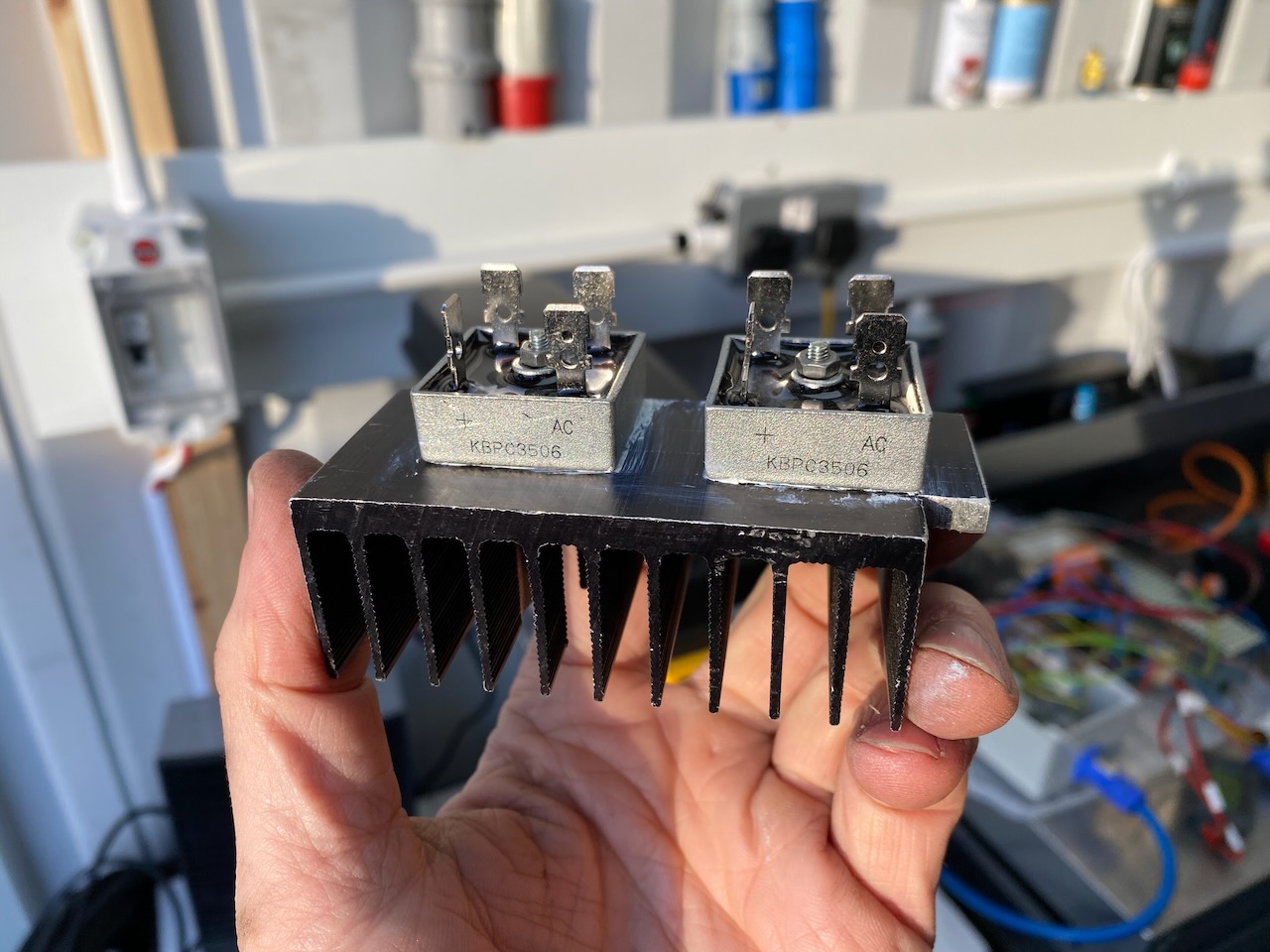
I prepared two KBPC3506 silicon bridge rectifiers on a heatsink. These are an inexpensive 35A 600V part available from many distributors.
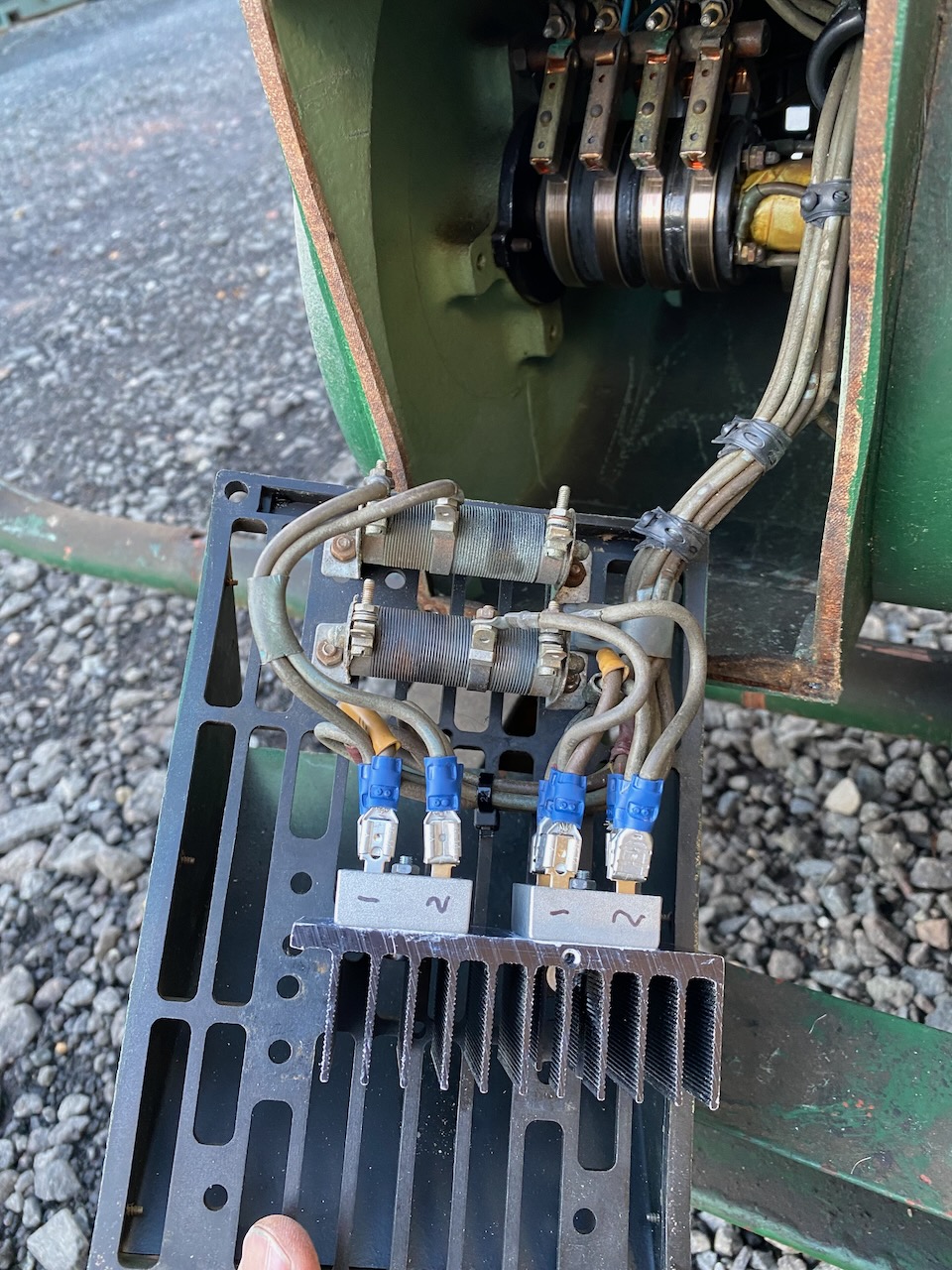
The new rectifiers are much smaller so I was able to get rid of a lot of wiring, and that sketchy looking woven tube that was probably asbestos.
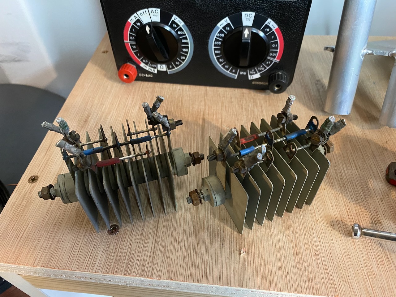
Of course I saved the original rectifiers, lol no, they went straight in the toxic waste.
Leave a Reply