When I started designing I already knew that the heart of the thing would be silicon carbide MOSFETs and diodes. I heard so much from Anders Mikkelsen of Advantics raving about how awesome they are. 🙂
On recommendation from Anders I chose the C3M0065100K MOSFET and C4D10120D diode. These are available from Farnell, Mouser etc. for about £10 each. I figured that 2 in parallel would allow me to run an inductor current of 32A RMS, a reasonable match to the mains supplies available in the UK and Europe. Anders also kindly donated an inductor capable of handling 32A RMS. 🙂
The remaining design decisions were set by the dumpster find of a large heatsink and set of 3 Semikron dual diode bricks. Having such a beefy oversized rectifier made short circuit protection easy: I just needed to come up with one more heavy duty diode to bypass the delicate SiC diodes, and then a short on the output would simply pop the circuit breakers on the mains input.
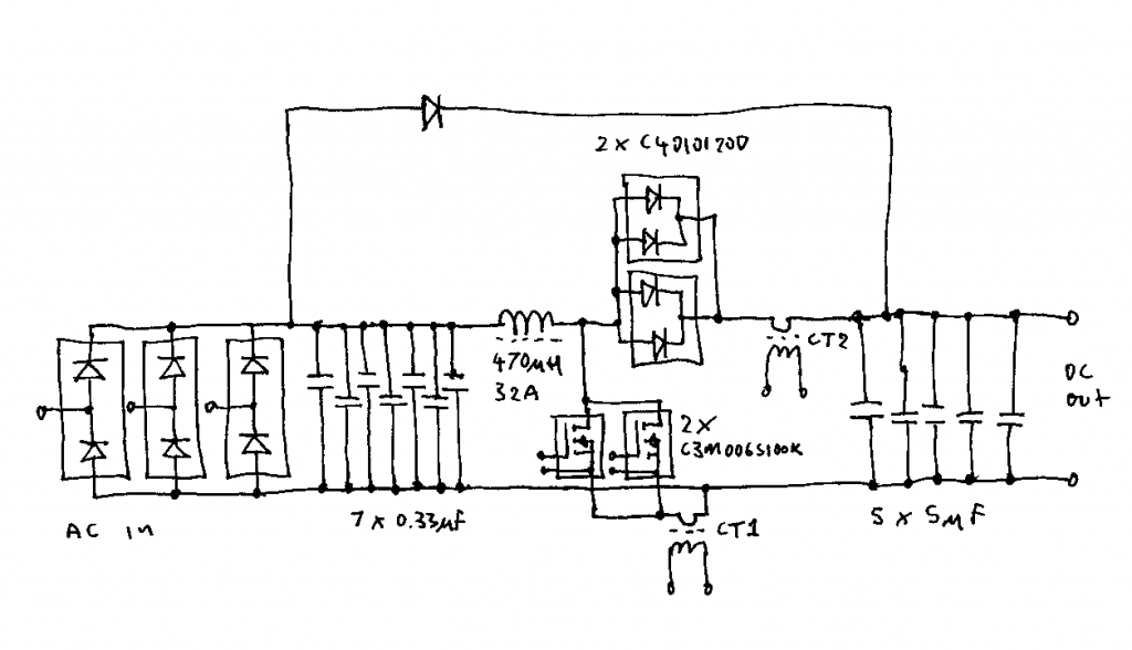
Schematic of the boost PFC engine
CT1 and CT2 are small ferrite cored 1:200 current transformers sensing the MOSFET and diode currents. Their outputs are combined in the controller to give the inductor current.
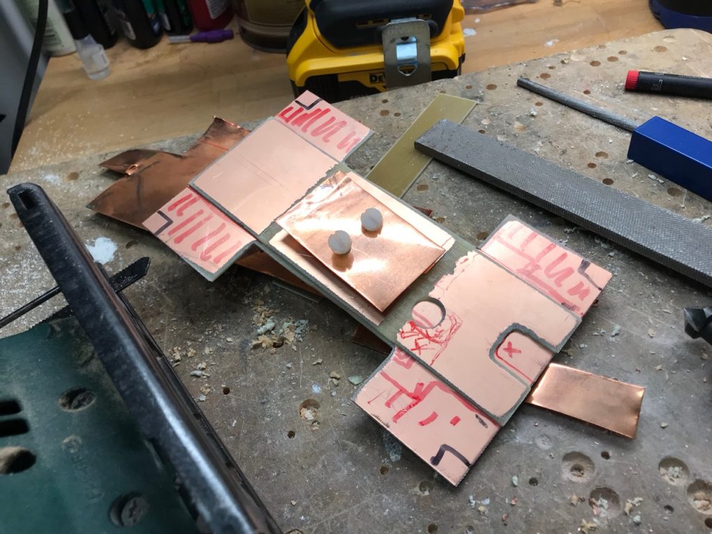
DIY 3 layer PCB 🙂
SiC MOSFETs can switch incredibly fast, so a good layout with minimal stray inductance is important. I decided to make a multi-layer structure out of pieces of single-sided copper-clad PCB and copper sheet.
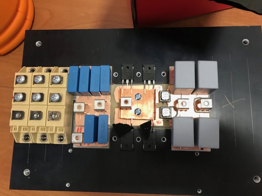
Trial fitment of the components.
I didn’t manage to fit as many capacitors as I wanted: only 5 on the input and 4 on the output. The output ones in particular will have a hard time with serious amounts of HF ripple current. They are only there to filter out the HF ripple. Large electrolytic capacitors will be needed to handle the power frequency ripple, they will be mounted somewhere else and connected by wires.
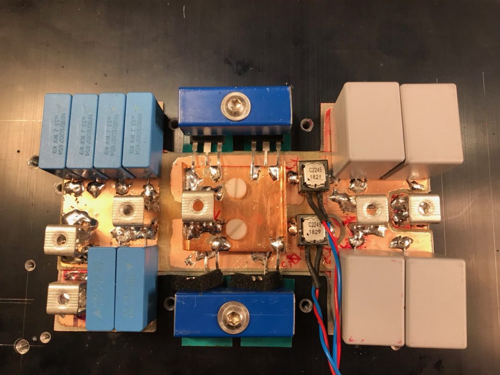
Assembled
Clamps for the MOSFETs and diodes made from pieces of Ikea cabinet legs. 🙂
I decided it was time to build a new power supply for Odin with power factor correction. (See all posts on the PFC)
Power factor what? To explain, we have to go back to the turn of the last century and the War of the Currents. Alternating current won so all of our mains supplies are AC. However, solid-state Tesla coils, like most power electronics, run off DC. Odin needs several kilowatts of power at about 750V DC.
The simplest way to achieve this is to use a voltage doubling rectifier on the 240V AC mains. I used this in my previous large solid-state Tesla coil, the OLTC2, with one small refinement. I used SCRs instead of diodes to allow soft starting and varying the output voltage.
The major drawback of this circuit is a very poor power factor, especially at reduced output voltage. It is particularly bad in a DRSSTC, as it has a huge capacitor on the DC bus for energy storage, and the rectifier charges this directly. I improved the power factor somewhat by connecting a large iron cored inductor in series with the incoming mains. This worked well enough, and you can see details of the old power supply herehere and here.
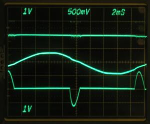
Gate pulses, line voltage and line current waveforms from the old PSU running at low output voltage.
I used this same power supply topology in Mjollnir, Little Cook and Odin. There was no room inside the smaller coils for the passive PFC inductor, so I used a much smaller one, making the power factor even worse. The shortcomings really became apparent in a few shows I did with Odin. It performed really badly when running off a generator, and there were two venues with 3 phase supply that I couldn’t use.
After much thought I decided to go for the simplest possible solution: a boost PFC. These are very common in larger consumer electronics, and controller ICs and design information are readily available. It is also easy to modify for 3 phase input. Essentially you just replace the rectifier with a 3 phase one. The line currents aren’t nice sine waves any more, but the power factor is still greatly improved over a plain rectifier with the same filter capacitance.
Probably the biggest drawback for Tesla coil use is that the output voltage can only be greater than the peak value of the rectified input voltage. You are limited to a minimum of about 400V when running off 240V single phase, and 600V from a 415V 3 phase supply. This is a problem for me at least because I like to check the tuning at reduced voltage after setting the coil up at a new venue.
Eventually I persuaded myself that I could live with this and set to work designing a boost PFC.
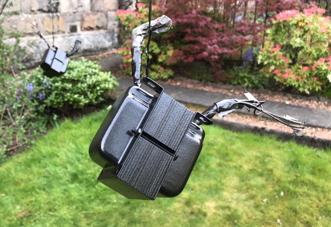
The Crown SXA has had black power transformers and silver/rust coloured output transformers for like a decade now 😉 The black Hammerite spray paint is great.
Ever since the Raspberry Pi came out, I’ve been experimenting with its audio capabilities. The latest audio gizmo available for it is the Wolfson Pi Audio Card, which promises 24 bit, 192kHz recording and playback, with analog and digital I/O, for a very reasonable price. So of course I ordered one straight away. 🙂
After waiting a month I finally got my hands on it. The software installation is somewhat unclear so I will document what I did here. I didn’t want to use the Wolfson official image as it was a massive 8GB download. I started with a copy of the image that I developed for PiTunes, and applied this patch to it, which adds the Wolfson kernel and the support files for the audio card. I then changed mpd.conf to use audio output device hw0,0 (it was previously 1,0 for the USB audio device) and added a call to SPDIF_playback.sh in my .bash_login file, to set the card up for digital output.
I also removed the invocation of pikeyd from /etc/rc.local, as the keypad and encoder were not present. They can’t be used anyway, since the Wolfson audio card hogs all of the GPIO pins. It doesn’t really matter, as MPD can always be controlled remotely.
On firing this up, I was surprised to find that it worked first time! 🙂 I verified the output to be bit perfect at 24 bit, 96kHz. This is possibly the best value for money HD audio source you can get anywhere: you should be able to pick up a Raspberry Pi, a Wolfson Audio Card, a wifi dongle and a hard disk for under £100.
This article (series of them with any luck) is inspired by Nick de Smith’s Quad 405 project. He was getting better distortion figures than my Blameless build: 0.002% at 20kHz! And from an amp that operated in Class-B and needed no bias adjustment or thermal compensation, how could this be? I had tried to understand the current dumping concept before, and failed, but this time I was determined!
So here is a simple, intuitive (and maybe even correct? 🙂 ) explanation of how current dumping works. Please refer to Snook’s DCD Mod-3 schematic, as well as the diagrams below, in which I’ve reduced the circuit to the bare minimum possible.
Current dumping amp simplified
You can see that the amp consists of three parts. First, a Class-A, current feedback error amp. In the DCD Mod-3 circuit, the inverting input of this amp is TR2 emitter, the non-inverting input is TR2 base, and the output is TR7 collector.
Second, a hefty Class-B output stage that runs with no idle current. In the DCD Mod-3 this is TR8, TR9, TR10 and associated parts.
Third, what Nick de Smith referred to as the “Maxwell-Wien Bridge”. This is obvious in the DCD Mod-3 schematic. I’ve drawn it in the same way here, but I’ve labelled the components Z1, Z2, Z3, Z4 in accordance with Walker and Albinson’s original analysis.
Then, to make things a little clearer, I’ve drawn the circuit again, but replaced Z2 and Z4 with resistors, of values roughly equivalent to their reactances at 20kHz.
We’re now in a position to see intuitively how the circuit works. The error amp is looking at the output from the output stage, fed back to its inverting input through Z1, and comparing it to the desired audio signal on its non-inverting input. It amplifies the error by a factor of -(Z2/Z1) which is -100 in my circuit. This amplified error drives the output stage, like in any normal audio amplifier. But a portion of it is also fed forward directly to the speaker through Z3. This forms a potential divider with Z4, so the speaker sees the fed-forward signal attenuated by a factor of roughly Z3/Z4, which is 100.
So, the error got amplified by -100 and then attenuated by 100 again. It follows that the error gain to the speaker is just -1. In other words, an equal and opposite signal cancelling the original error, to give a perfect output. So, we’ve rederived the original Walker balance condition: Z2/Z1 = Z3/Z4, or Z1Z3 = Z2Z4 as Walker wrote it.
(I’ve taken some liberties with a “1” here and there: the potential divider really attenuates by a factor of 101. But so did Walker and Albinson and everyone else. I’ve also assumed that the output stage’s output impedance is negligible, and its input impedance is high enough not to load the error amp down and kill the feedforward signal. Again, I believe these assumptions were also made in the Quad 405 design.)
However, as every amplifier geek knows, Z2 is a capacitor and Z4 is an inductor. In fact, I remember Quad’s full page ads in the hi-fi press, that showed nothing but a picture of the inductor and the Queen’s Award logo.
Intuitively, what now happens is that the error amp integrates the error, but Z3 and Z4 are now a high-pass network that differentiates it again, so the feedforward works just the same as if Z2 and Z4 were resistive. But using reactances leads to some elegant synergies: each one ends up doing at least two good things at once, hence presumably the Queen’s Award.
Using a capacitor for Z2 gives classic dominant pole “Miller” compensation for the error amp, with all the associated benefits.
Using an inductor for Z4 saves power, isolates the output stage from nasty capacitive loads, and low-pass filters the remaining distortion harmonics.
Indeed, Z2 is the compensation cap, and Z4 the output coil, that most classic power amp designs need anyway. The only component that a classic amp doesn’t have is Z3. This suggests to me that an ordinary amp could be converted to a current dumper by just adding a resistor from the driver stage through to the speaker end of the output coil. (It also suggests that Quad’s ads should have showed a 47 ohm resistor instead of an inductor.)
A current-feedback amp with a hefty driver, like the Alexander, seems like it would be the best candidate, but I think it should be possible with a “Blameless” type voltage-feedback circuit, too. The only complication is that when you go to voltage feedback, Z1 isn’t a single resistor any more. Its effective value, as far as bridge balance is concerned, is the attenuation through the feedback network, divided by the input stage transconductance.
I could be wrong, but if this is true then the usual Blameless values give a value for Z1 of about 2500 ohms. That means the output coil would need to be 5 times bigger, or Z3 5 times smaller. That makes it 8 ohms, so in order to drive it, the error amp becomes an output stage and we’re back to square one! So, the Alexander is a much more attractive candidate for conversion, as it has Z1 = 750 ohms and Z2 = 100pF, giving a value for Z3/Z4 similar to the Quad 405.
I’ll leave you with a puzzle: In the DCD Mod-3 circuit (and indeed every other Quad 405 circuit) what are D5 and D13 for?


