The PFC engine is working, but there are a few other things needed to make it usable. (Operationalise it? Or Heaven forbid, weaponise it? 🙂 )
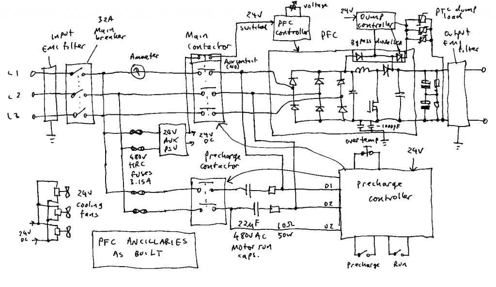
Auxiliary power supply: The PFC needs a small amount of power to run its own control electronics. I decided to use a Meanwell WDR-120-24 switching power supply to provide 24V DC. This is an industrial grade unit that will accept any input voltage from 200 to 500V AC.
The WDR-120-24 is a bit more expensive than the usual 85-265V input range units, but vital for my goal of being able to run the PFC off either 230V single phase or 400V 3 phase power, without any kind of voltage selector switch that could cause carnage if set wrongly.
Precharge: The bus capacitance of the DRSSTC is very substantial. Odin has 4700uF after a recent upgrade. The PFC itself will also need another 1000uF to allow it to work without the DRSSTC connected. All of this has to be charged to the peak value of the mains voltage before the PFC can even start, in an orderly manner without tripping any breakers.
I chose a capacitive ballast for this job, consisting of 22uF motor run capacitors with 10 ohm resistors in series. The capacitors do most of the current limiting while the resistors protect the capacitors and main contactor from the surge when the capacitors are shorted out. The resistors are attached to the main heatsink and protected by the overtemperature cutout.
The precharge controller is based around a time delay and voltage sensing relay. (Schematic in a future post) The voltage between D1 and D2 must get over 200V, and the voltage between D2 and U2 below about 20V, before the sensing relay will pull in. This energises the main contactor, connecting the PFC input rectifier directly to the mains, and powering up the PFC controller through its auxiliary contact. The PFC then goes through its own soft start procedure, charging the DC bus capacitance to full voltage.
Dump load: The large DC bus capacitance also needs discharged when the system is powered down. My previous coils all relied on bleed resistors and took over a minute to discharge. For this build I decided to try some PTC thermistors from Epcos. (Details in a future post.)
The main advantage of PTCs is that, unlike normal resistors, they limit their own temperature and won’t catch fire or explode if the switch controlling them accidentally turns on while the DC bus is powered. This allows me to switch them with a SCR which was already present in the bypass diode module.
EMI filtering: This is as much to protect the PFC from damage by the huge transients generated by the Tesla coil, as to protect the mains from the hash thrown out by the PFC. My search for suitable off-the-shelf EMI filters is documented in another post.
Leave a Reply