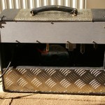
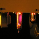
Ninja Corvette Hybrid

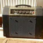
This is another long-running project that started out as a Selmer Corvette practice amp obtained from a junk shop. The Corvette was an inexpensive 3 watt practice amp, equipped with two ECC83/12AX7 valves (one for amplifying, another for a tremolo oscillator) one EL84 and one EZ80 rectifier. The whole lot blasting through an 8″ Elac speaker in a fetching croc-skin covered cabinet, with hardboard back, gold plexi front panel, and grill cloth in a shade I can only describe as “porridge” πŸ™‚

When received, it contained the original Mullard tubes and was in working order. It hummed a lot, the knobs crackled when turned, and the tremolo sounded a bit sputtery. But, it had a nice fat tone that turned into a really vicious grind at full volume. Think of a tiny raging Marshall with a hint of malfunctioning Fuzz Face.

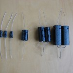
I started by cleaning the pots with contact cleaner, cleaning the cabinet, and replacing the input jack sockets and all of the electrolytic caps. This didn’t make much difference to the tone, and it still hummed. So, I added a choke to the power supply, which got rid of the hum nicely. I played it like this for a long time, it was a handy amp for practice and jam sessions. I even used it at a few gigs, but it wasn’t loud enough.

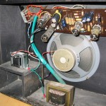
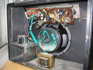
One day it got a huge hole ripped in the porridge grill cloth while kicking around my car, so I decided to mod it some more. I ripped off the old cloth, enlarged the speaker hole, and installed an Eminence Beta 8 that I had lying around, with a new wire mesh grill. That didn’t make it any louder, and it still sounded much the same, but it didn’t flap and fart so uselessly at high volume.

Then I had a crazy idea. I knew that this little amp really longed to be a monster that would make Marshall stacks flee in terror. πŸ™‚ And, it now had a speaker that could stand much more power. Why not make it into a hybrid? In the lab, I cooked up a transistor output stage inspired by the ones in the old Thomas Vox and Leslie power amps, that could be driven off the existing output transformer. When I switched it on, I was expecting it to explode or sound terrible. But to my surprise, it sounded just like the original amp, only louder. A lot louder! My first prototype measured 70 watts before clipping.

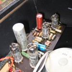
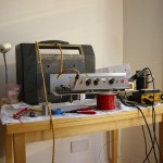
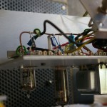
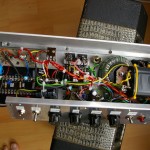
This concept lay around as a half-finished breadboard for months, as I was so busy with work, but eventually I got around to rebuilding it. I tossed out the original Selmer PCB and built a new aluminium chassis, that would hold all the valve and solid-state parts, and double as a heatsink for the output transistors. I rebuilt the original Corvette circuit with fresh components, using point-to-point wiring on tagboards, tube sockets on rubber shock mounts, and leaving out the tremolo. I also added a MOSFET follower to vary the screen voltage, and dumped the rectifier tube in favour of some silicon diodes.

The old tremolo speed knob became the screen voltage control, and the old depth knob became a 3-position switch, that selected the original 3 watt output, or 0.3 watts through an attenuator, or about 30 from the solid-state output stage. It actually measured 42W clean, so I hit the 30W target with a little to spare.

The result was amazingly successful. Well, I think so anyway. πŸ™‚ Hmm, that EL84 is getting a bit too hot.

https://youtu.be/DZigVupYve4
Demo on Youtube.

High quality version of video soundtrack

This was recorded with no (dynamic range) compression, so the 0.3 watt setting is very quiet.

Schematic

Schematic (Rev.2)

Schematic of standalone output stage
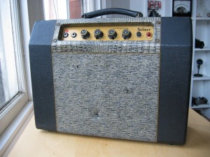
Eventually a 10″ speaker was added

11 Replies to “Ninja Corvette Hybrid”

  1. Sort of reminds me of an old Gibson Falcon I am working on juicing up a bit. On a side note do you have any experience using tubes robbed from an organ? I recently came across an old organ in the trash and impulsively pulled all the tubes out of it. I wanted to take the whole thing but the wife had a fit over the Hammond m-3 I parked in the living room.

    1. An organ should have plenty of the same kinds of tubes you find in guitar amps. 12AX7s, 6V6s, EL84s, etc. They should be good quality ones too. Hammond used tubes from makers like Mullard/Philips, RCA, and the like, and rebranded them as “Hammond” tubes.

  2. I love it! I have a tiny formerly solid state DOD combo that’s just begging for something like this!

    I just had a thought, please don’t hate me for it. Maybe you could an effect loop between the tiny tube amp and the solid state amp. I guess that’d just be like using a herzog and would defeat the whole purpose of the solid state and tube outputs interacting.

  3. Hi,
    You’re hybrid amp is really nice. Well done! I definately want to try to make my amp an hybrid as well.
    I have a question:
    – The part of the schematic you call “Pair O’ Boots”, is it giving a gain or is it adding wattage? (to get 30W total instead of 3W)? You said you also reached 42W. In the case of a SE 9W amp, can I use the same “Pair O’ Boots” or it will clip due to the higher initial input?

    Thanks a lot for sharing that!!

  4. The “Pair O’ Boots” is a current controlled current source that outputs roughly 10x the current driven into it by the tube amp. Not quite 10x because the output transistors need some drive current.

    This ratio is controlled by R26, R27 being 10x the value of R24, R25. To use the Pair O’ Boots with a higher powered tube amp, reduce the value of R26, R27 to get the gain you want. I think I ended up reducing them to 2.2 ohm because the gain was too much even for a 3W driver.

    R30, R31 also reduce the gain, but they are mainly there to control the output impedance. Increase them for less speaker damping.

  5. Thanks for your reply!

    So I could put a double linear pot instead of R26 and R27 and I will get a volume on the “Pair O’ Boots”? Would it work?

    If at gain “1”, I want full amp output, do I need to remove R30 and R31 that are damping the speaker?

    I’m not sure, but is your design is similar to Tubecad:
    http://www.tubecad.com/2013/04/blog0261.htm
    (second schematic after “Actually Building a Power Booster”)
    If not, what would be the main differences?
    If yes, you did it a long time before he thinks about it!

    Sorry, I’m very newbie. I may ask simple (stupid) questions…

    Thank!!

  6. If you can find an 0.47 ohm dual gang pot! Good luck with that :p I would like to add a volume control to this circuit but I haven’t figured out how yet.

    R30, R31 affect the tone. The larger the value, the brighter the speaker gets.

    I started with an idea similar to the Tubecad one about 10 years ago. http://scopeboy.com/boots.html The circuit I have now is based on the same concept, but simplified as much as possible. The Tubecad one would be easier to modify with a volume control. In this image http://www.tubecad.com/2013/04/19/LM4780%20Amplifier-Power%20Booster%204X.png you would replace the 1k resistor between non-inverting input and ground, with a 1k pot.

Leave a Reply

Your email address will not be published. Required fields are marked *