With the chassis suitably butchered it was time to start on the electronics. I used Mark Huss’s schematic as a guide.
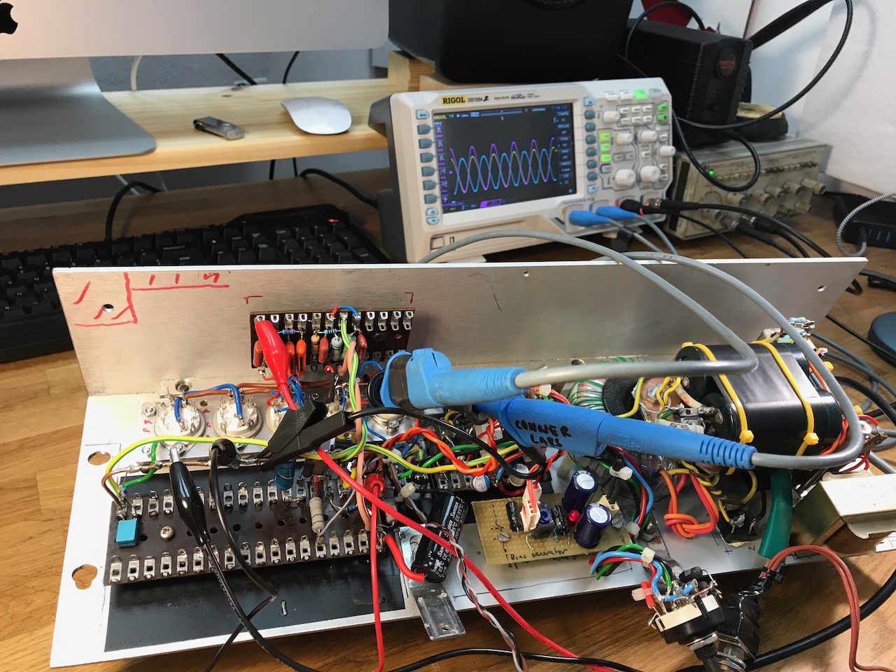
Soon the phase inverter and power amp were finished and working.
One big difference is that the 2204 uses negative feedback around the output stage while the original Corvette didn’t. So I decided to go with the NFB, and include the transistor output stage in the feedback loop too for an extra challenge.
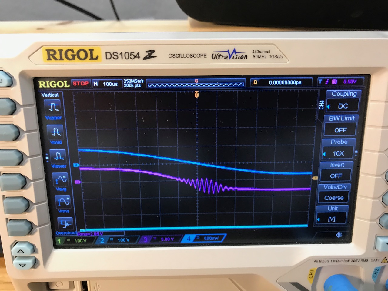
It was perfectly stable first time! LOL just kidding… It suffered from high frequency parasitics-
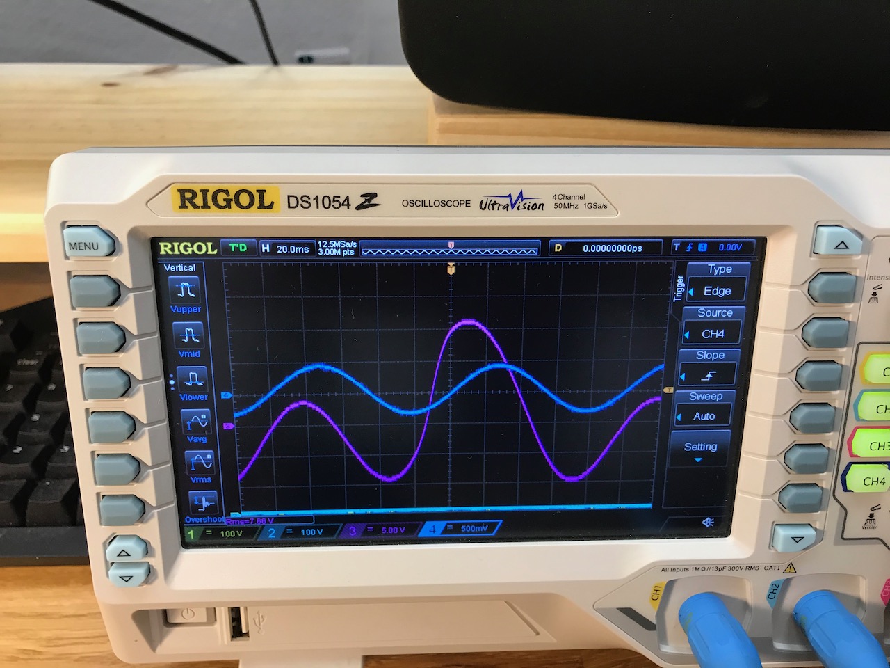
And these comically chaotic LF oscillations could be provoked by overdriving it at low frequencies.
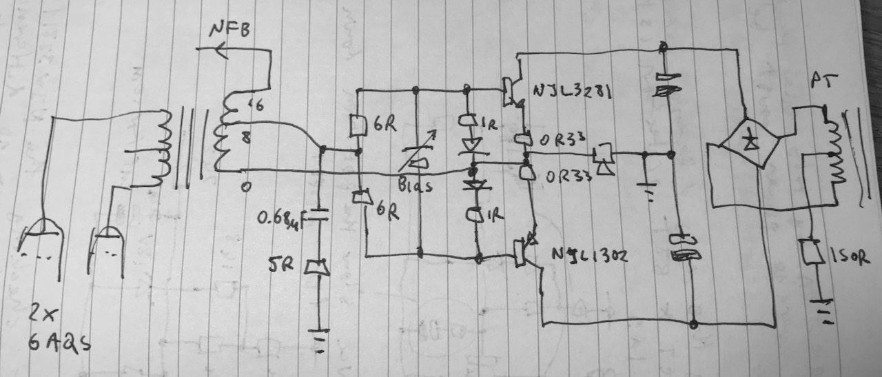
After much trial and error I ended up with something like this. The 0.68uF/5 ohm RC snubber killed the HF oscillations, and removing C17 and C18 (this schematic) stopped the motorboating. With these values it was just barely stable with the load disconnected and a 220k NFB resistor (vs 100k in the original 2203 circuit)
Note that when the transistor output stage is in play, the OPT secondary becomes bootstrapped and flies around with the speaker output, so the NFB takeoff point I used sees the output voltage of the transistor stage plus the output voltage of the valve OPT.
Removing C17 and C18 demanded quite a lot of extra current from the bias generator, but it seemed to deliver it no problem, so no changes were required there.
Resistor values were also changed to reduce the current gain of the transistor output stage, due to the increased output of the valve part of the circuit.
Leave a Reply