Finally the long awaited test happened 🙂 (you can read all posts about the PFC here)
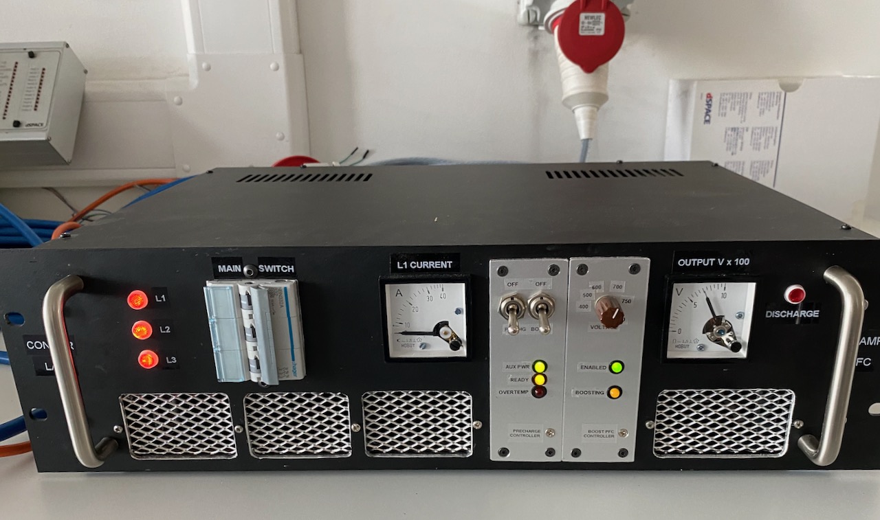
We plugged it into the 3 phase outlet and it started up normally! 😀
When smashed with 750V the Tesla cabin heater would draw an impressive amount of power while warming up. Unfortunately the steady state power draw was only about 2kW, probably something to do with the rather weak fan cooling it.
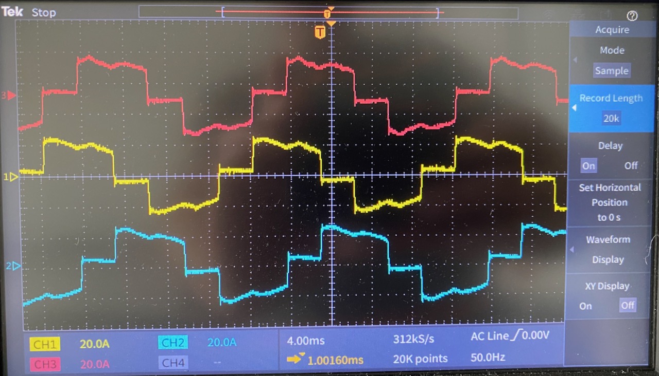
The PFC line current waveforms at (roughly) this 11kW output power level. No surprises here, they look exactly like the theoretical ones for this circuit. (Except strictly speaking the red one is upside down 🙂 ) The theoretical power factor for this waveform is 0.95.

We don’t have a 3 phase power analyser in the lab, so I used 2 single phase ones on the input, according to the old “2 wattmeter method“. To be honest this didn’t work very well, as the power drawn by the PTC heater was always changing, and it was impossible to make sure the 2 meter readings corresponded to exactly the same time. Also, the PF reading is rubbish due to the inherent 30 degree phase shift: to get the actual PF you have to plug the wattage readings into a complicated formula.
When the heater reached steady state, I measured an input power of 2000W, an output of 1900W, and a power factor of 0.96. From an academic point of view it would have been nice to measure the efficiency at higher powers, I expect that 100W is mostly switching losses and the efficiency will increase with heavier loads.
The main goal was to get confidence that the PFC would work at its first gig, and this has been achieved 🙂
Leave a Reply to Mads Barnkob Cancel reply