[In this episode of the Chinesium Mine, we dabble in the home energy storage market]
I’ve loved playing with batteries ever since I was a kid, except for one horrible incident with a Burgess Safari Lite battery that put me off testing them with my tongue for life. More recently, electric vehicles and grid-scale battery energy storage have become A Thing, and all have standardised on the lithium iron phosphate battery (aka LiFePO4, LFP) so I thought I’d better get one for professional development. 🙂
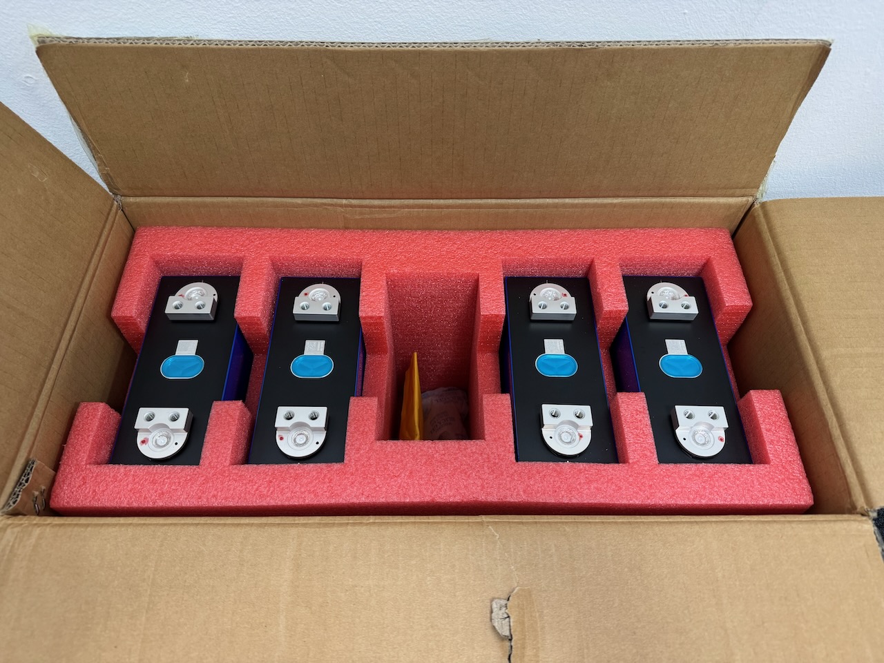
Besides 100 different types of vape battery, Fogstar also sell large prismatic LFP cells and all kinds of accessories to build your own battery pack. I opted for their 12V DIY bundle with the EVE MB31 cells. Shipping 20kg of lithium ion batteries could have turned into a nightmare, but they were delivered with absolutely no hassles.
A word of warning: Similar LFP cells can be found very cheaply on Ebay, Amazon, AliExpress, but buyer beware. There are a LOT of factory rejects and pulls from failed battery packs out there. I was reasonably confident that the Fogstar ones would be good.
At only 3.2 volts each, the risk of another Burgess Safari Lite incident is minimal.
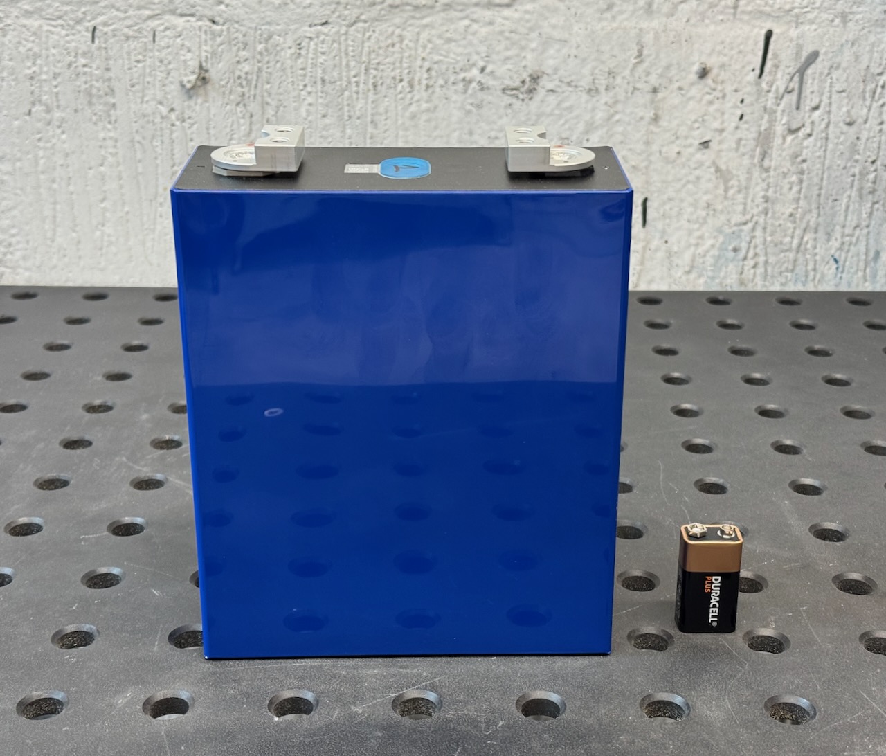
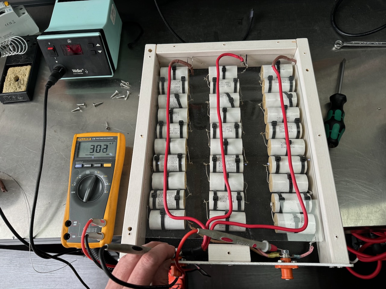
It’s not all about voltage though. These have a capacity of 314 amp-hours and can deliver a lot of current.
After doing some experiments with the raw cells [document in future and insert link] it was time to assemble the kit.
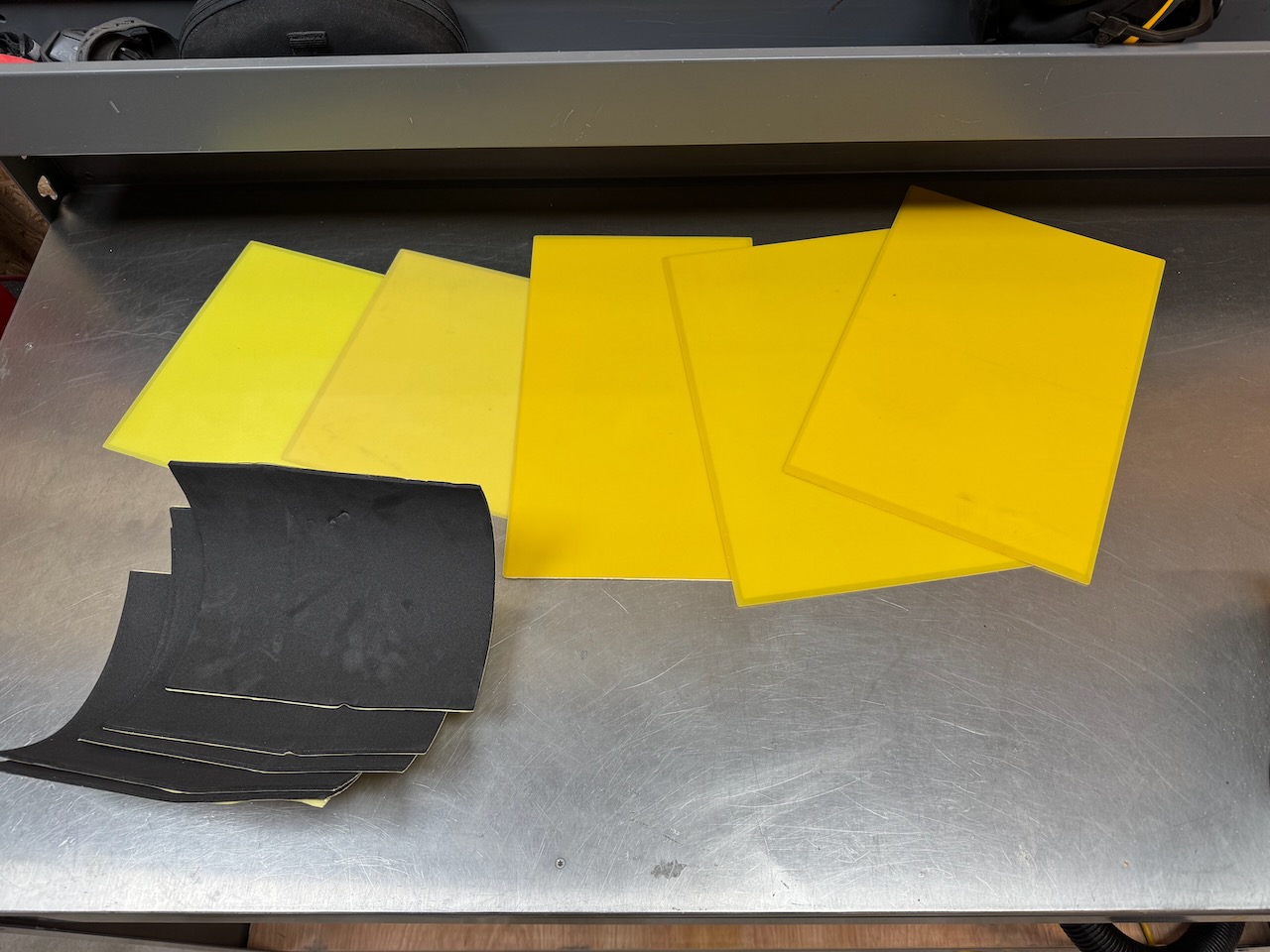
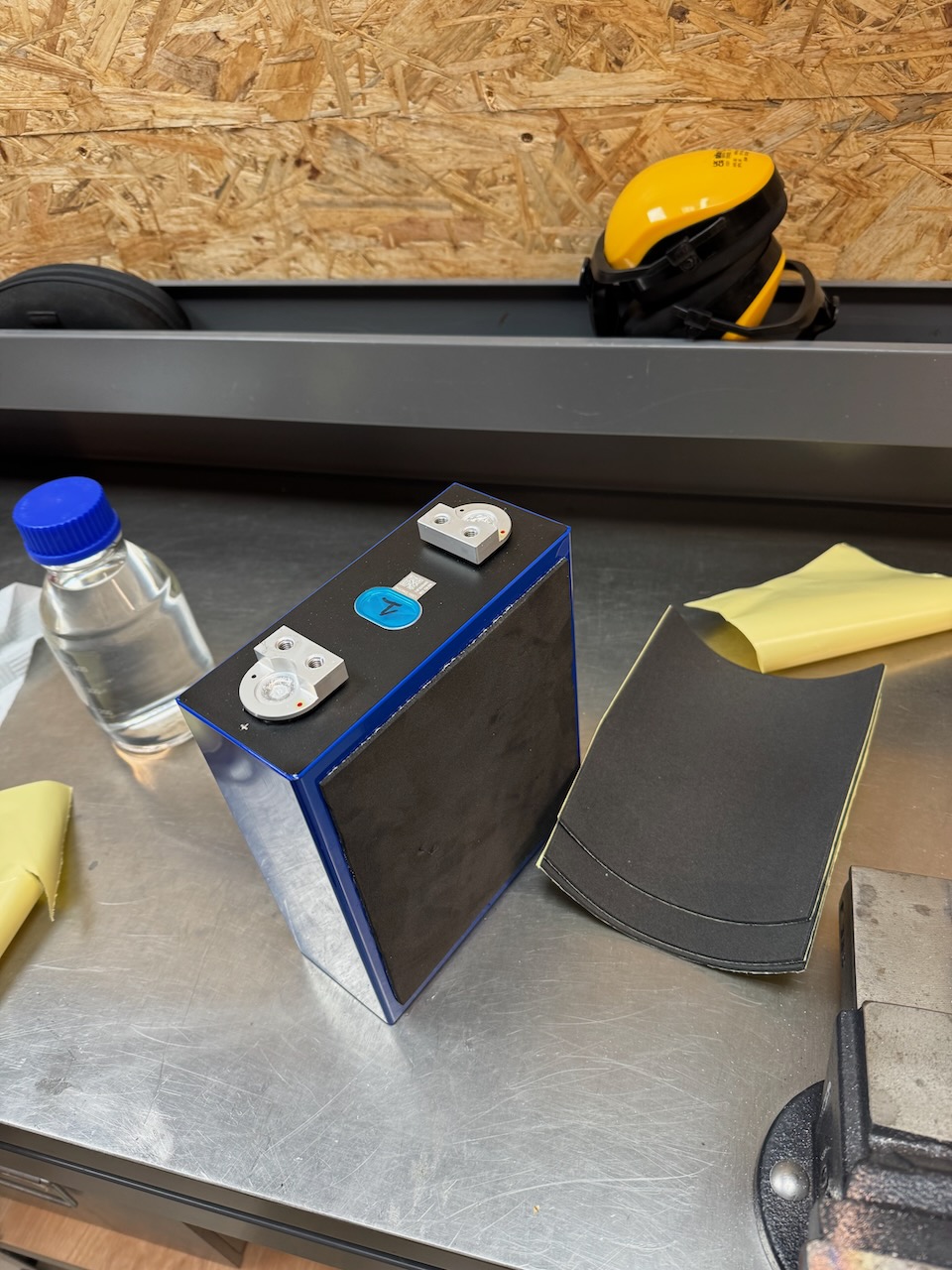
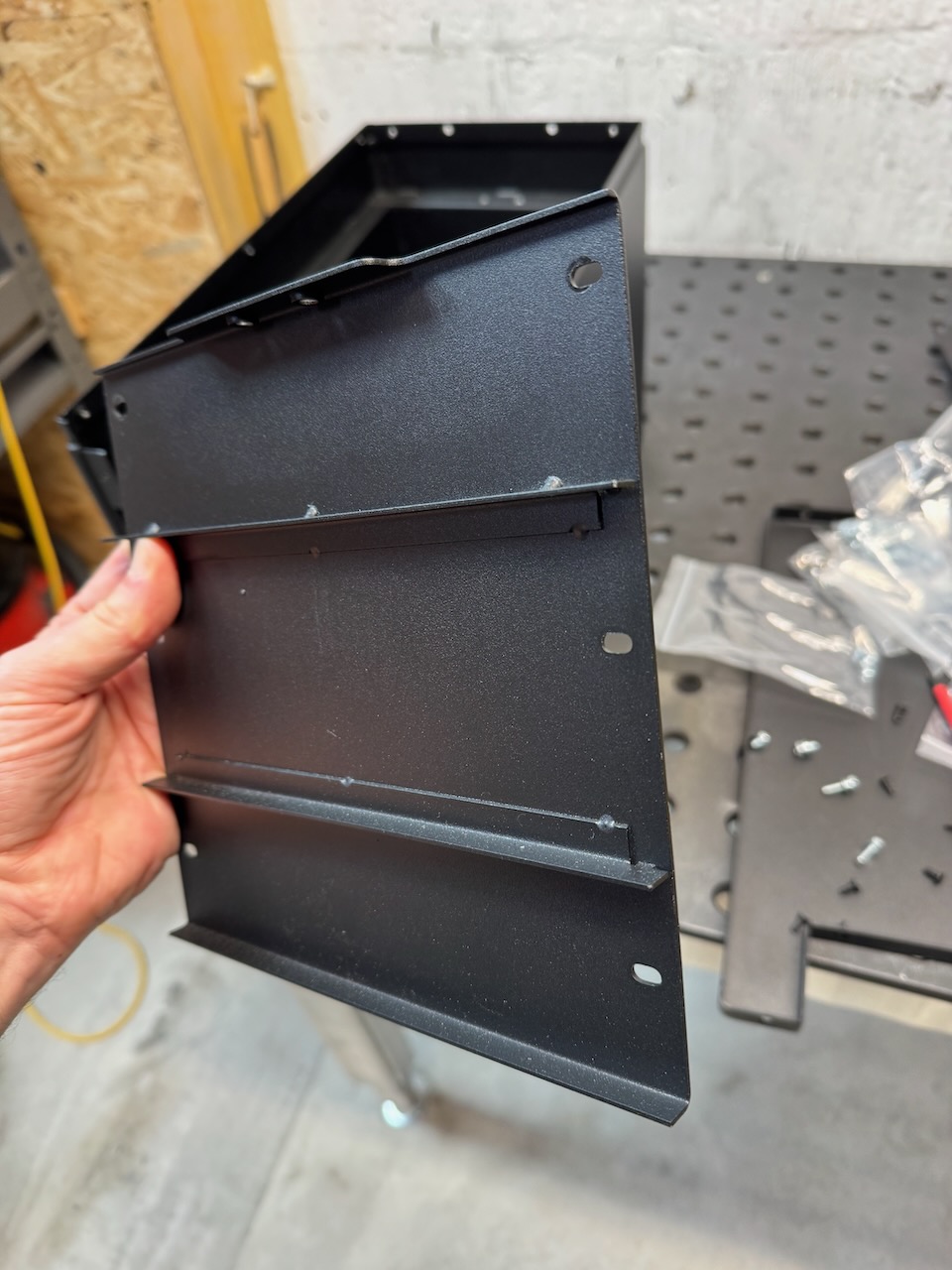
Internet best practice says that the blue plastic wrap can’t be relied on for electrical insulation, and the manufacturers say that the cells need some pressure applied to their broad sides for optimal cycle life. The Fogstar kit covered both of these bases: FR4 glass fibre sheets were supplied to line the metal battery box, and foam pads to go between the cells. All sticky backed for Blue Peter nostalgia.
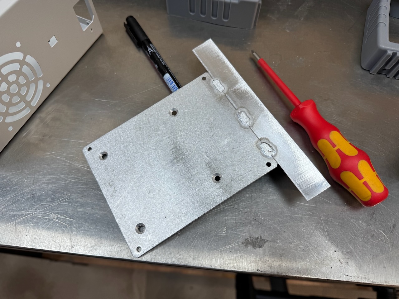
EVE’s recommended compression force for their cells is 300kg! I’d be surprised if this metal plate and its 6 screws were up to that amount of force.
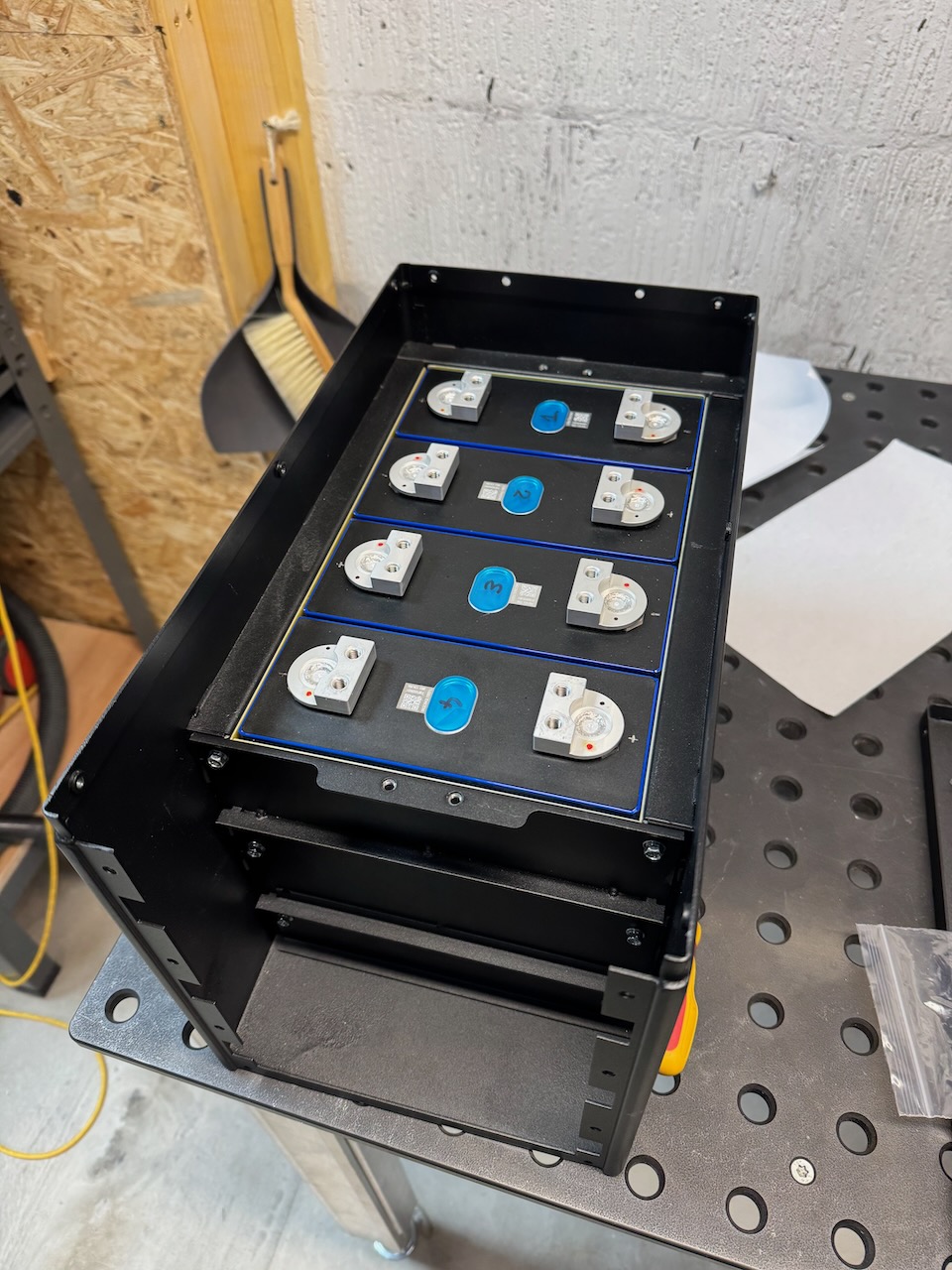
Having said that, it did seem to squish the foam pads down a bit and clamp the cells in place firmly.
The next step was to fit this clamping bar over the tops of the cells, complete with a sticky backed foam gasket on the underside. The main purpose of it seems to be to stop the cells falling out if the battery is turned upside down. (At this point it’s worth mentioning that LFP cells are completely sealed and won’t leak electrolyte unless something goes very badly wrong. I’ve seen them mounted in almost all orientations, but they probably work best with terminals up.)
They are also rumoured to expand slightly as they charge. For my 12V stack, it probably works out to less than 1mm of expansion between empty and full. This is why the busbars supplied with the kit are flexible.
LFP are similar to the other lithium ion chemistries, in that they have no ability to self balance, and no tolerance of overcharging or discharging to very low voltages. A single incident can turn your new cell into a “spicy pillow“. The cell bloats up with gas and is ruined for good.(though to be fair, LFP spicy pillows are much less likely to catch fire or explode than the other chemistries)
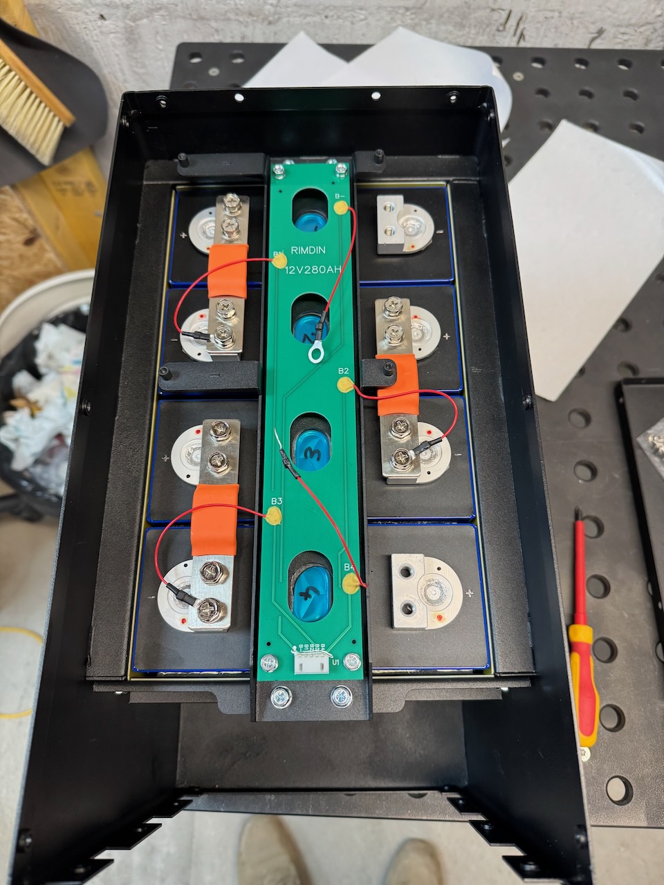
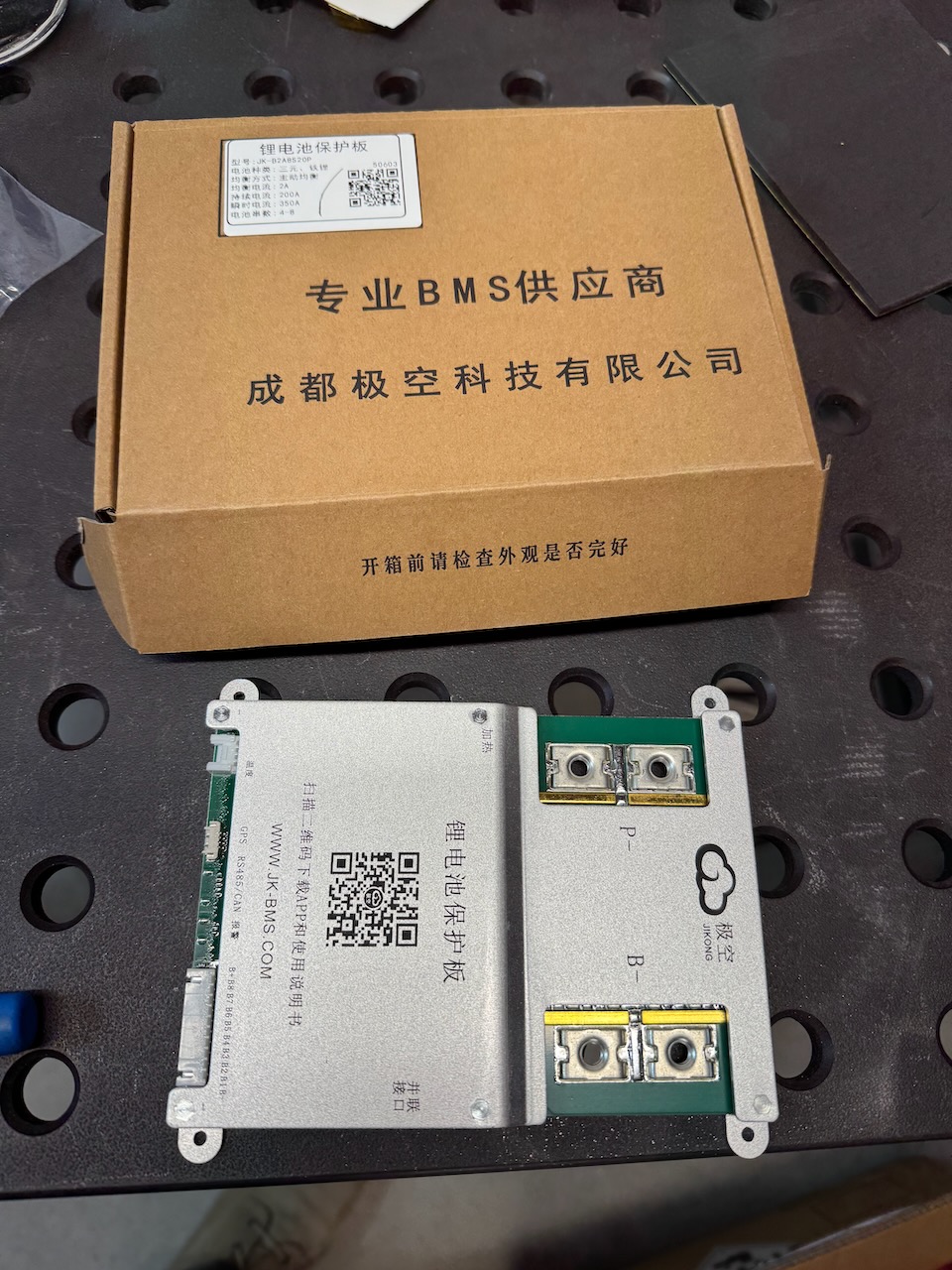
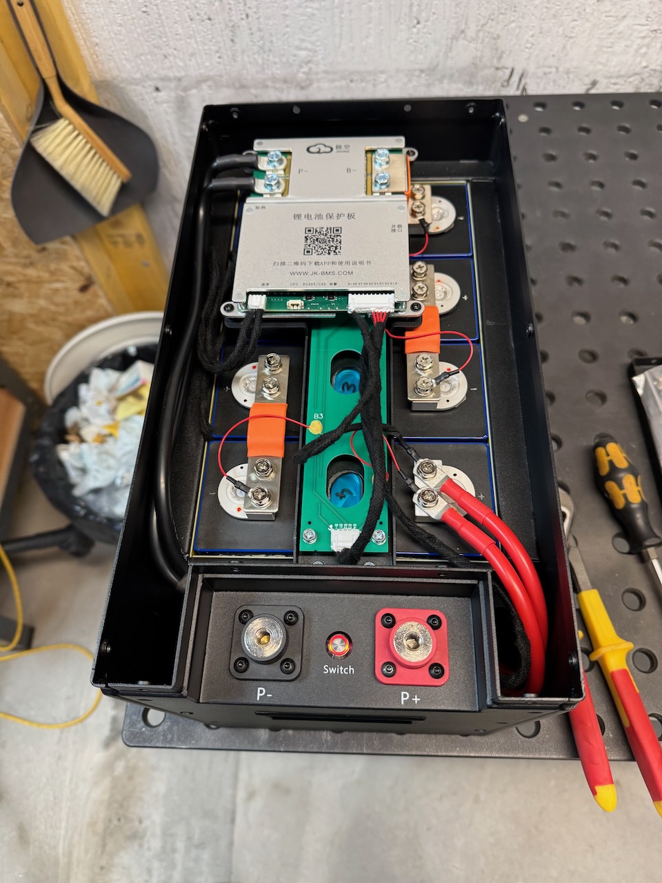
To make sure the cells stay nice and prismatic, we need a BMS. The two most popular brands seem to be JK and JBD. My bundle included a JK 200 amp model with 2A active balancer.
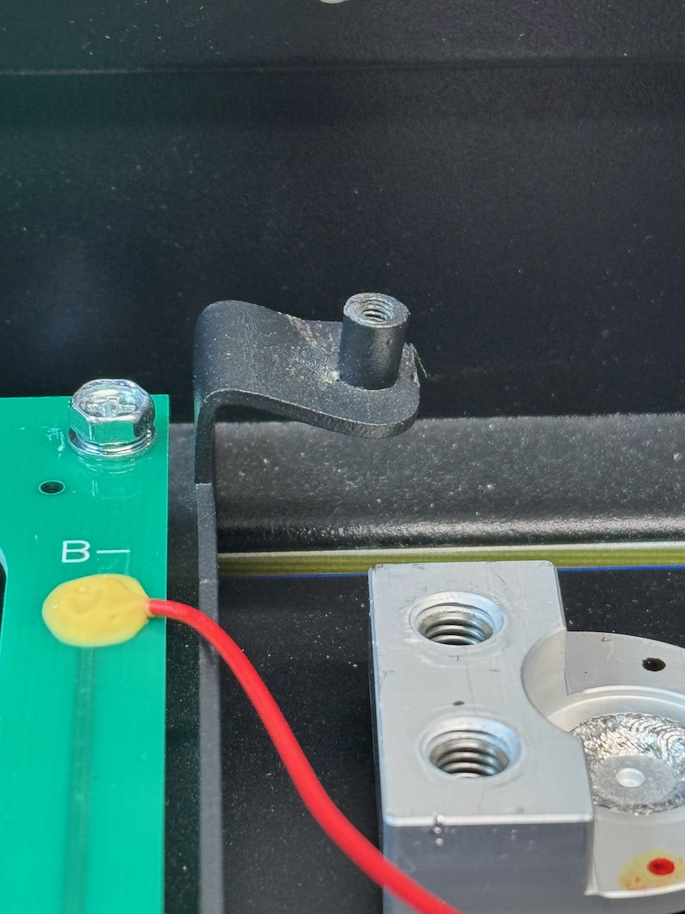
The mounting locations for the BMS needed a bit of gentle adjustment with a screwdriver, hammer and pliers. Out of the box, the BMS sat too high and the busbar connecting it to cell 1 negative put a lot of strain on the circuit board.

I liked the terminals and cable/wire harnesses supplied with the kit.

They even included a 400 amp ceramic Mega fuse in case the BMS overcurrent protection fails. LFP might not be prone to catching fire themselves, but they most certainly can supply enough current to start a fire.
Now came the hardest part of the build, did I mention that I’ve had enough of dodgy software to last me a lifetime? The BMS is configured and operated over Bluetooth by a smartphone app. It has two passwords, one to view status, and a different one to edit the settings. And nowhere do JK tell you what the default passwords are, or even that there are two. (For future reference, the view-only is 1234 and the settings password is 123456)
Victron use a Bluetooth PIN on their gizmos and notify you right in their app that the default is 000000. But their equivalent LFP battery costs 4x what this one did…
Eventually I got into it and was able to select the LFP battery type and enter the actual capacity of 314Ah. To be fair, the JK BMS app seemed pretty good apart from the out-of-box experience with passwords.
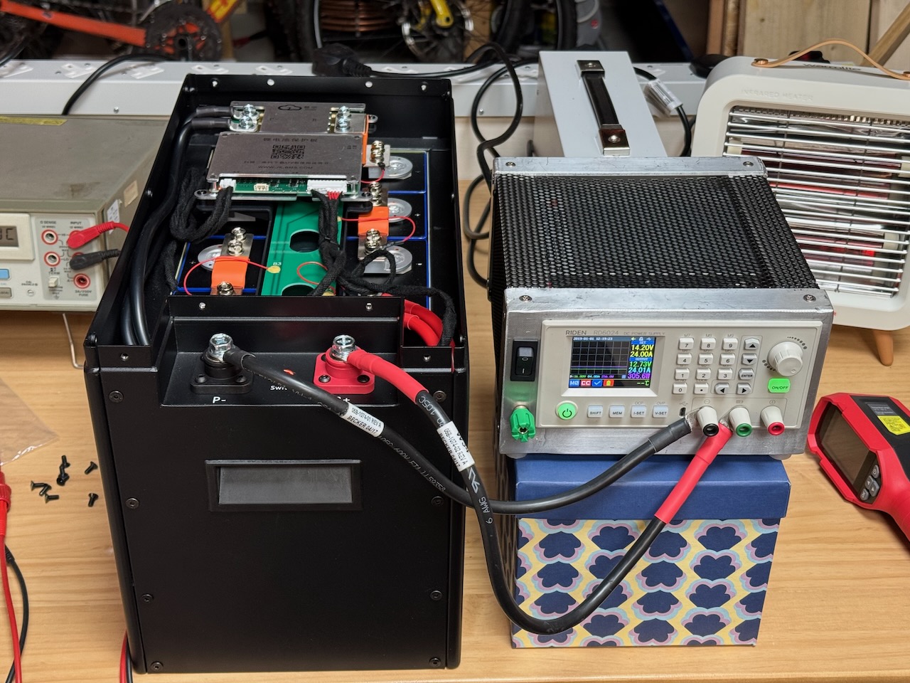
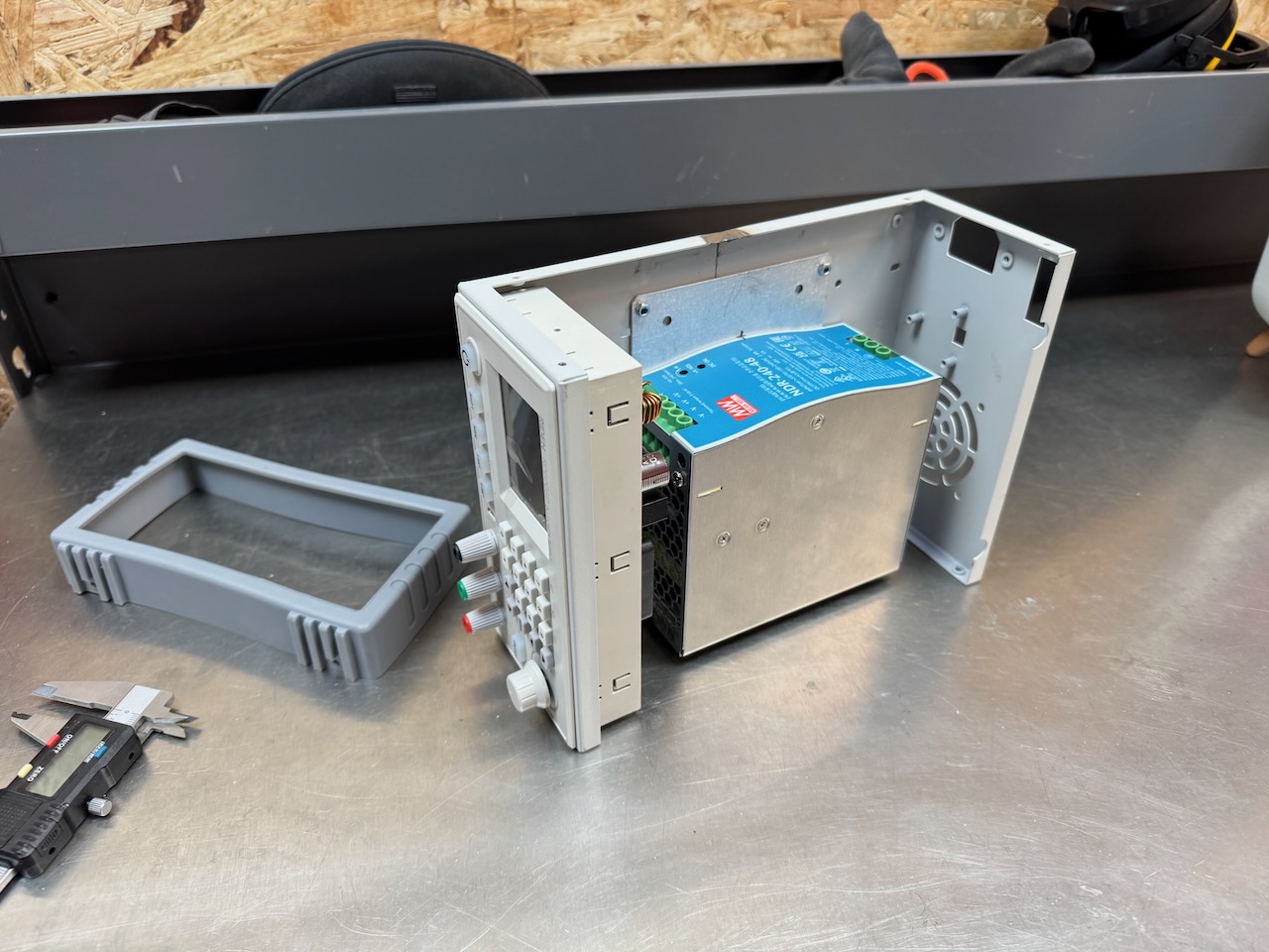
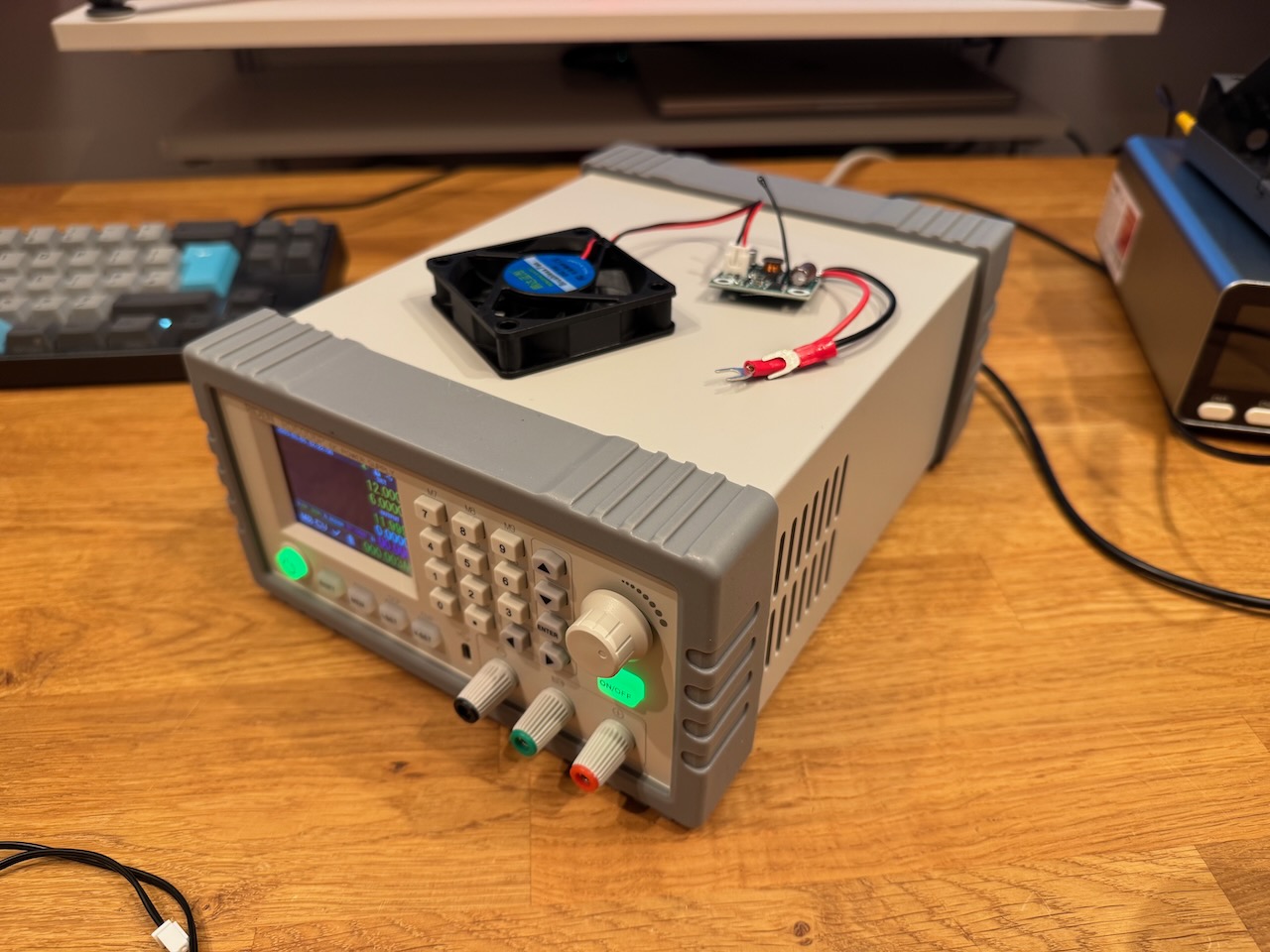
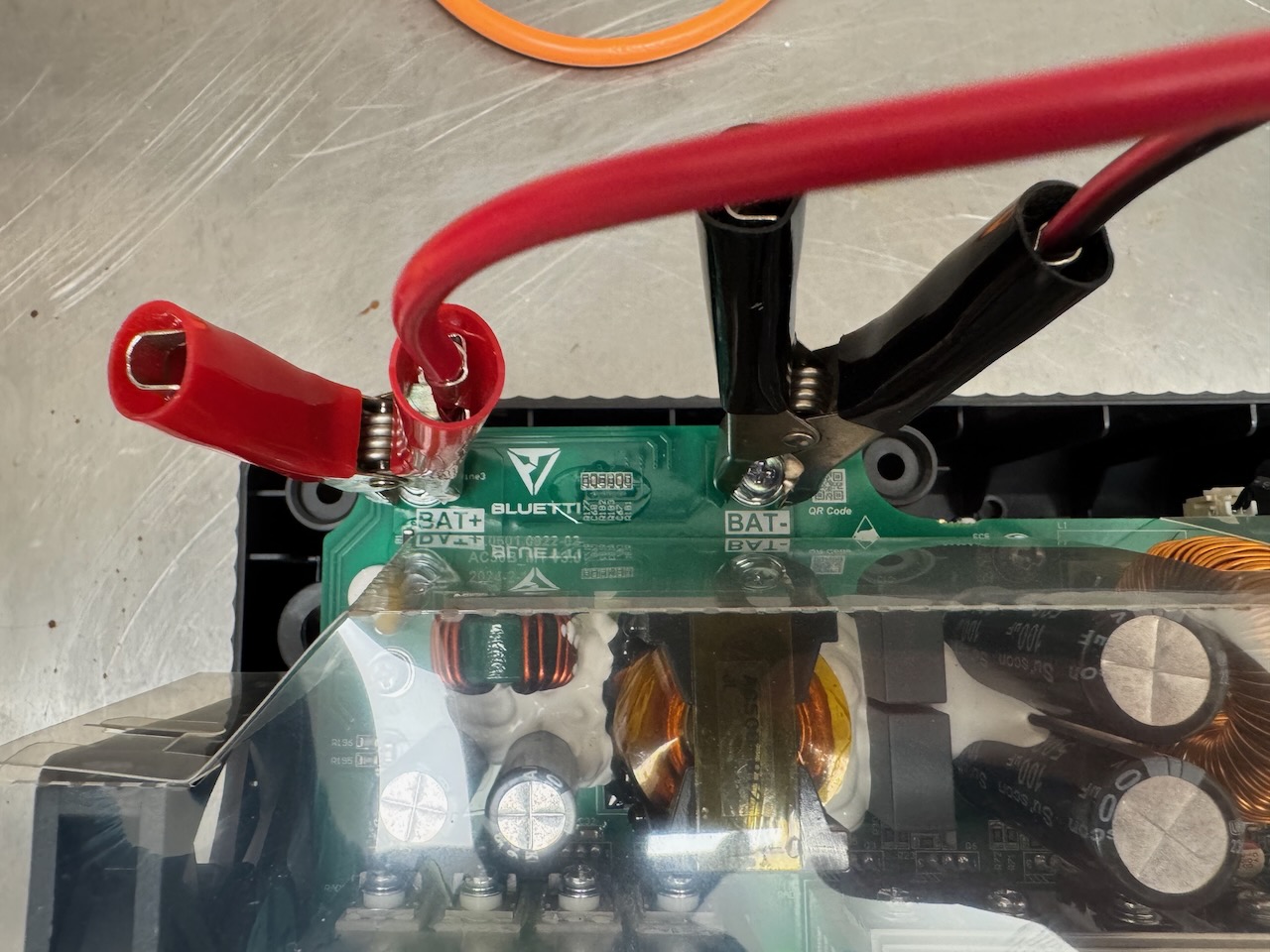
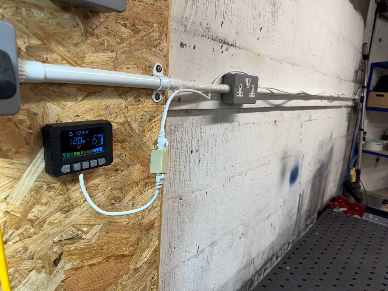
Then the first charge could commence… I set the Riden RD6024 (another golden nugget of Chinesium) to 24A, 14.2V, and a charge termination current of 5A.

With 24A into an almost completely empty 314Ah battery, the first charge took rather long. When I came back the next day it had finished, and both the Riden and the BMS showed almost exactly 314Ah input to the battery.
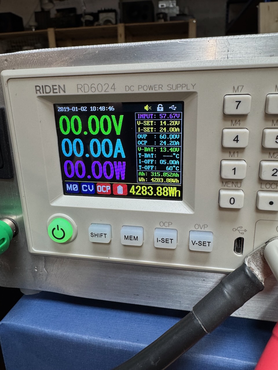
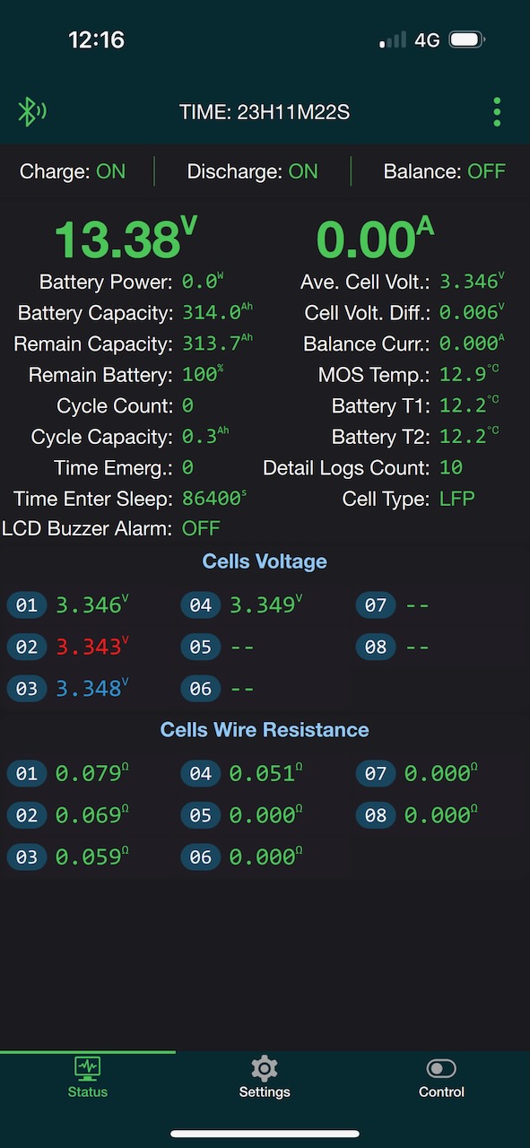
Which was oddly satisfying 🙂
All in all, this is one serious piece of Chinesium. The cells were brand new with no signs of previous use or tampering with the QR codes. They were very well matched and delivered exactly the advertised capacity. The BMS worked out of the box and its voltage, current and capacity measurements were reasonably accurate.
And the kit came from a UK dealer and has a warranty! It hardly even qualifies as Chinesium, except that the cells and BMS are so proudly made in China. Did I mention that China absolutely cornered the market in LFP?
It just misses out on the highest grade because there was no documentation whatsoever. Like none.
🀄️🀄️🀄️🀄️ Reactor grade Chinesium
