[Building a new battery for a 2009 Zero X]
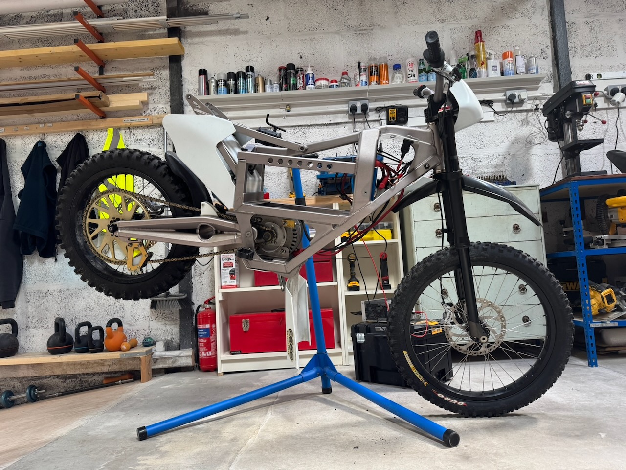
This electric motorcycle arrived at Conner Labs with a sad empty hole where the battery should have been.
The battery connected with a standard Anderson plug and another smaller 2 pin connector. Could it be some annoying custom BMS data connection? Or just a battery temperature sensor? I opened negotiations by stuffing a 10k resistor into the small plug and connecting a 48V power supply to the large one.
The dashboard lit up and the rear wheel turned, which seemed pretty encouraging.
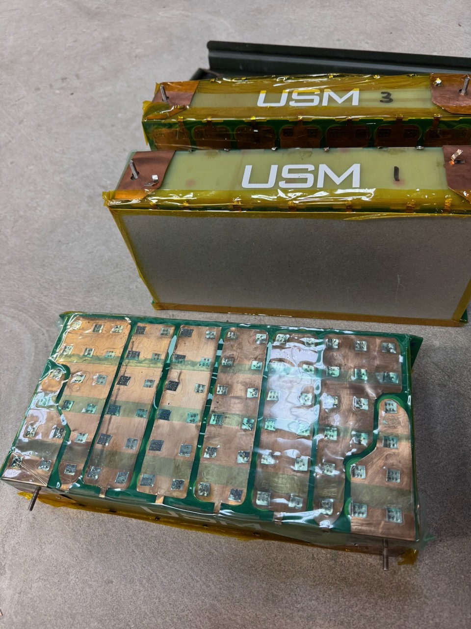
Soon after, some battery modules from a Formula Student electric race car also turned up. Thanks University of Strathclyde Motorsport 🙂
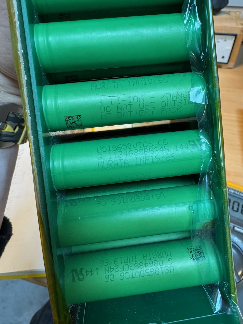
Ooh, Sony/Murata VTC6 cells, I wonder what state of health they are in?
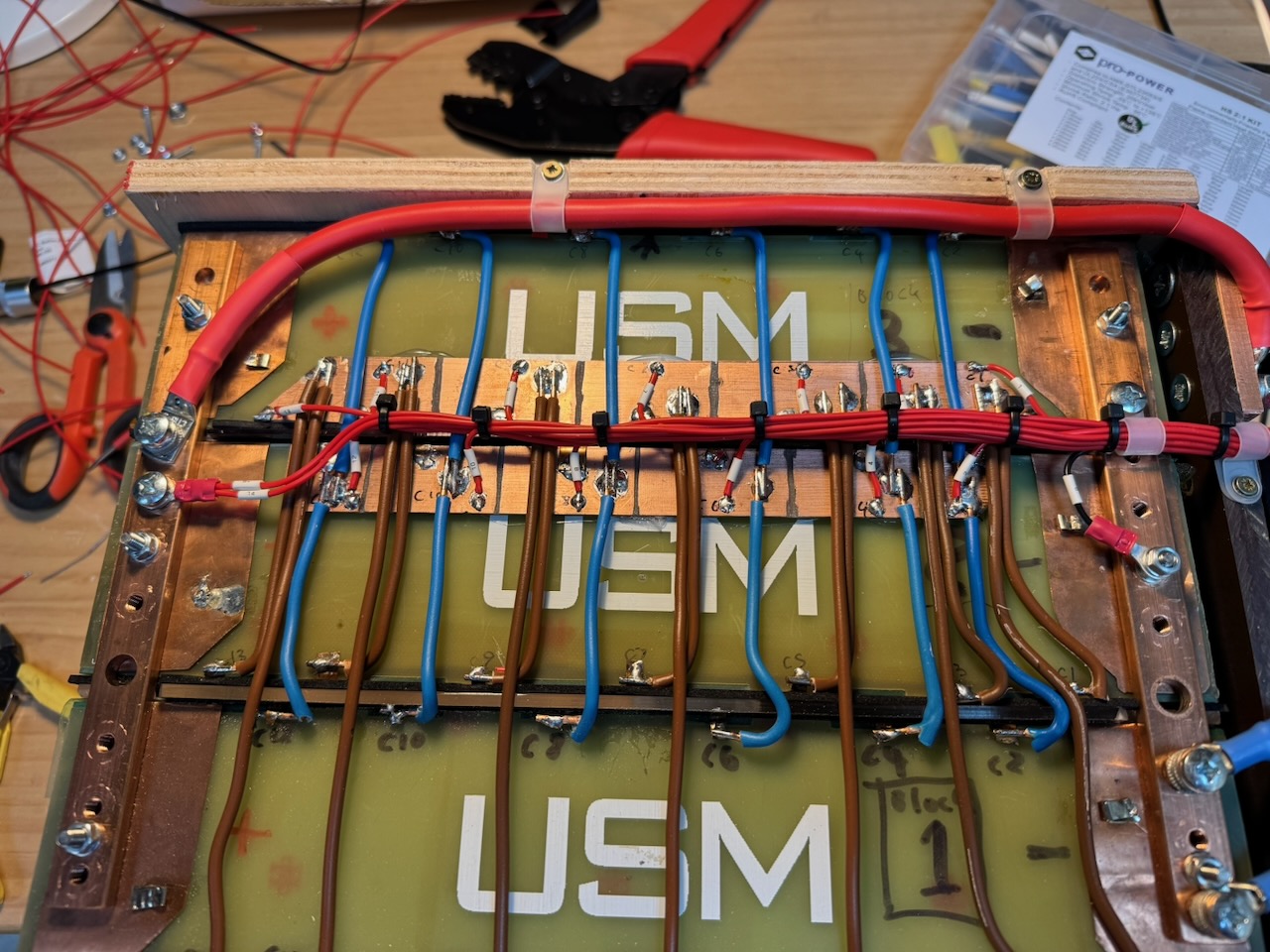
These modules are 14S6P, and in a stunning coincidence, the Zero’s original battery was also 14S.
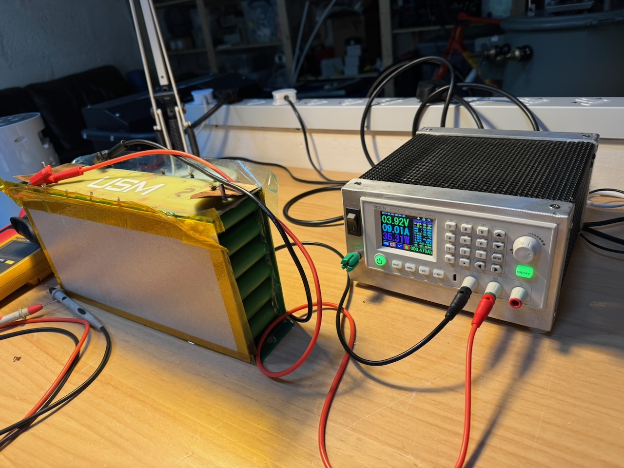
Using a bench power supply, I charged each section of each module to 4.1V. The Riden RD6024 has a dedicated battery charging terminal and tail current cutoff mode that hopefully made for more consistent results. The amp-hours needed varied wildly between sections, showing that the battery was indeed badly out of balance.
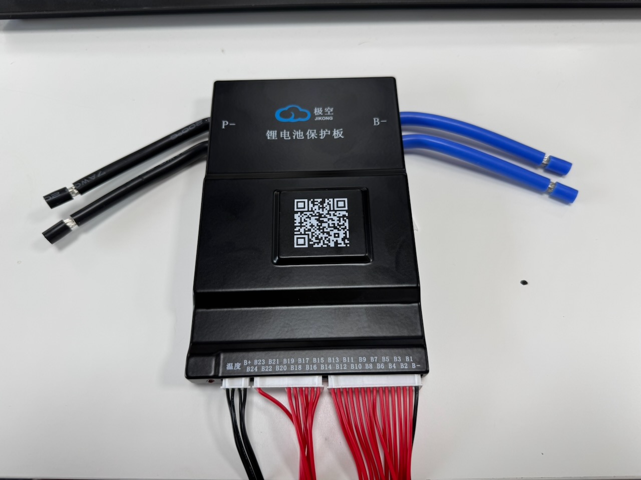
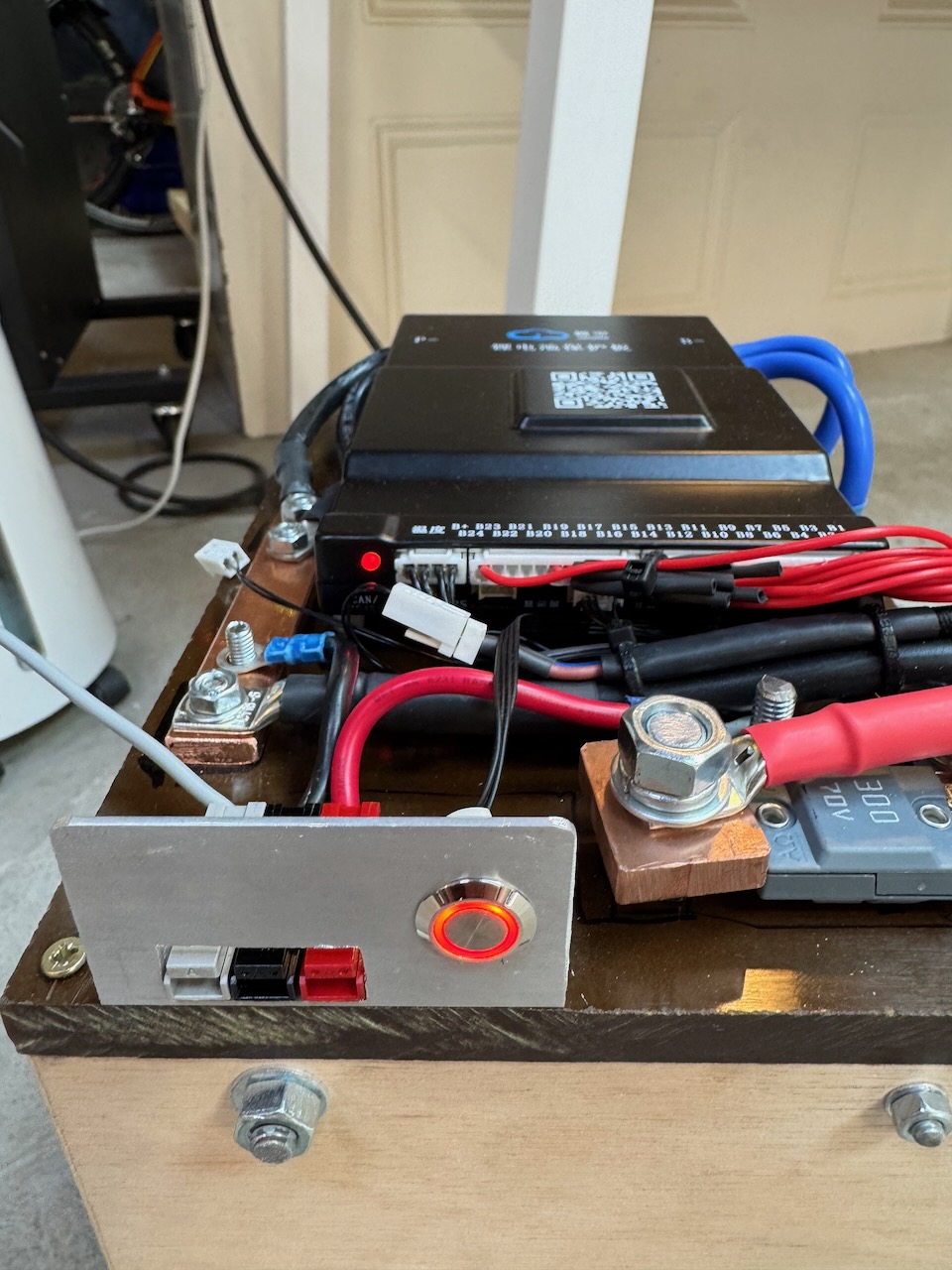
Once I could see that I had enough good cells to build a battery, I bought a BMS (JK B2A20S20P) This is rated at 200A continuous, 350A peak, and the bike’s controller (an Alltrax NPX) is rated 300A peak, so hopefully it will be up to the job. I’ve used the JK BMS before and it wasn’t a complete disaster.
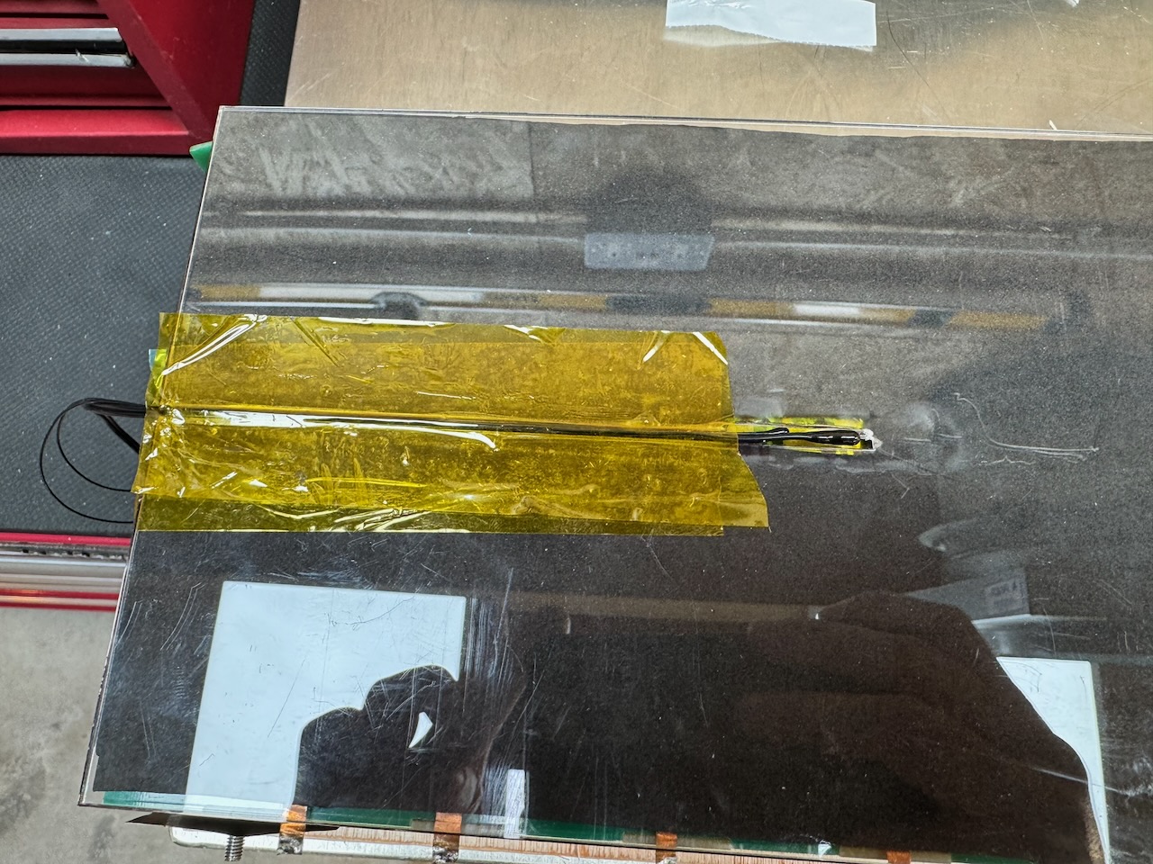
I got some laser cut acrylic spacers with slots for the BMS temperature sensors (and 2 more 10k NTCs, one for the bike’s dashboard and one for the charger)
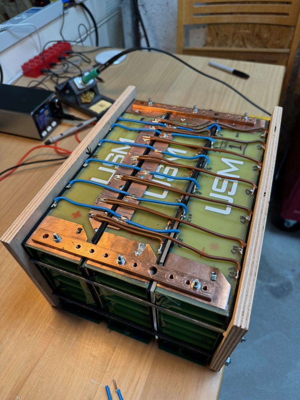
Then clamped it all together with some Plywood Aided Design ™ Just a temporary fix of course, if it fits the bike’s battery compartment and performs well, some more fire and water resistant material will be substituted in future. I promise lol.
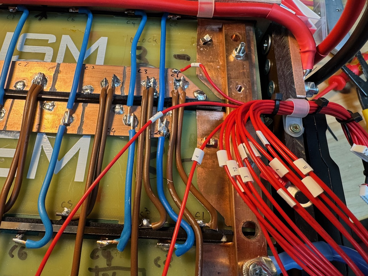
You might notice that I connected all of the cell taps of all of the blocks in parallel. The correctness of this approach is debatable :/ but I thought it was a reasonable compromise, compared to an individual BMS for each string.
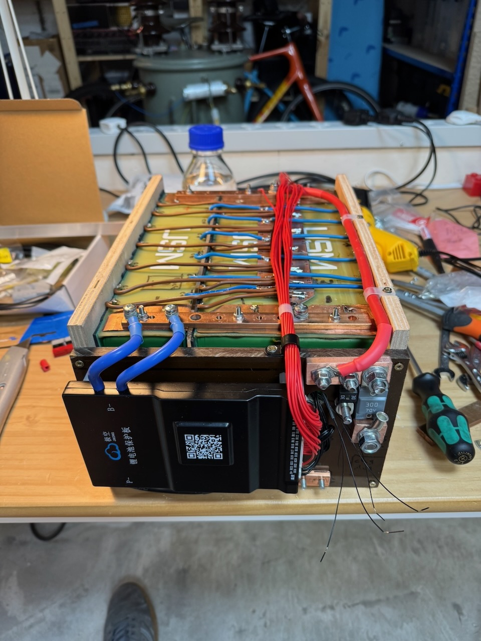
I mounted the BMS and fuses on a Tufnol end plate. Even for a temporary fix we can’t risk these coming loose and causing a short circuit.
The days of marking wires with splodges of permanent marker are over at Conner Labs.
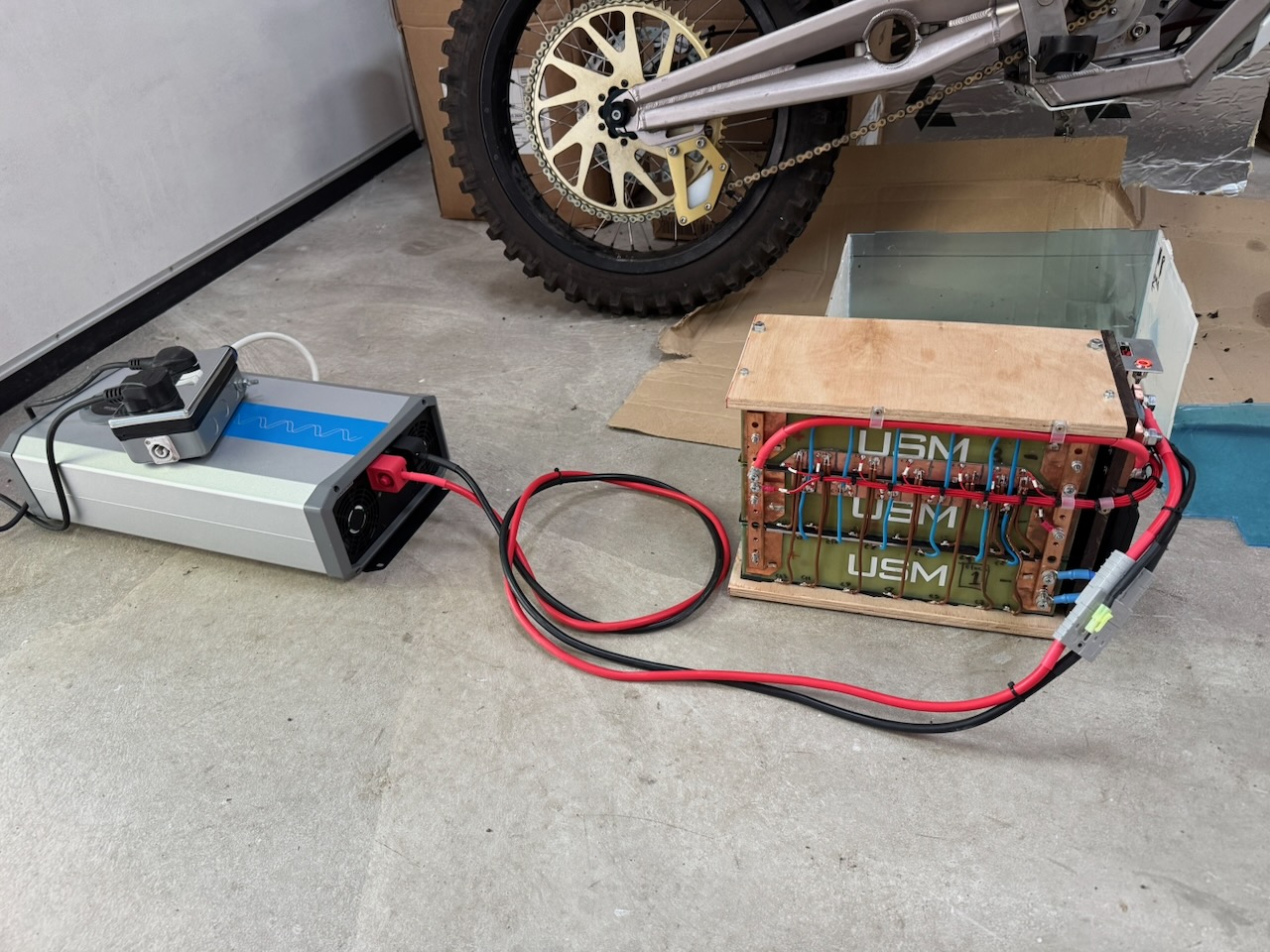
Soon it was time for the battery’s first cycle, for which I borrowed a 48V inverter as a load.
With 2500W of load on my 50V, 54Ah battery I expected it to last a bit over an hour. At this point there was a slight disappointment as the discharge was ended by cell 3 undervoltage at only two-thirds of the expected capacity. 🙁
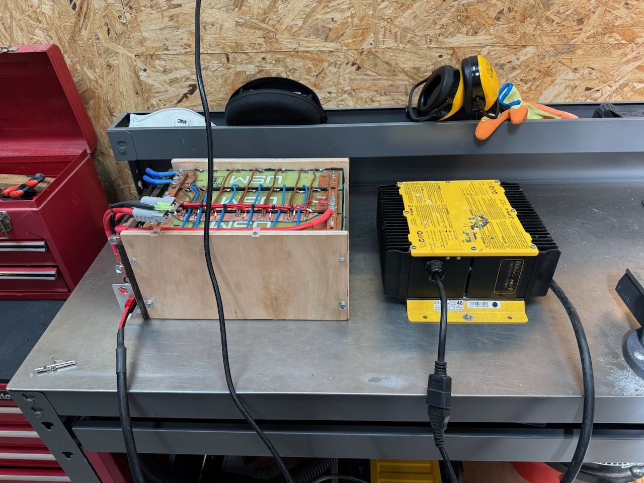
Then it was time to attempt a recharge with the Delta-Q QuiQ charger supplied with the bike. It would sometimes cut out at random with a sequence of flashing lights that wasn’t documented anywhere. For future me and others reading, the white wire is not for a temperature sensor! Just connect it to the black one to make the charger run.
Also, these chargers have programmable firmware with a selection of different algorithms. Mine were labelled lead-acid but had been reflashed with a custom “algorithm 99” that was in fact for 14S lithium ion.
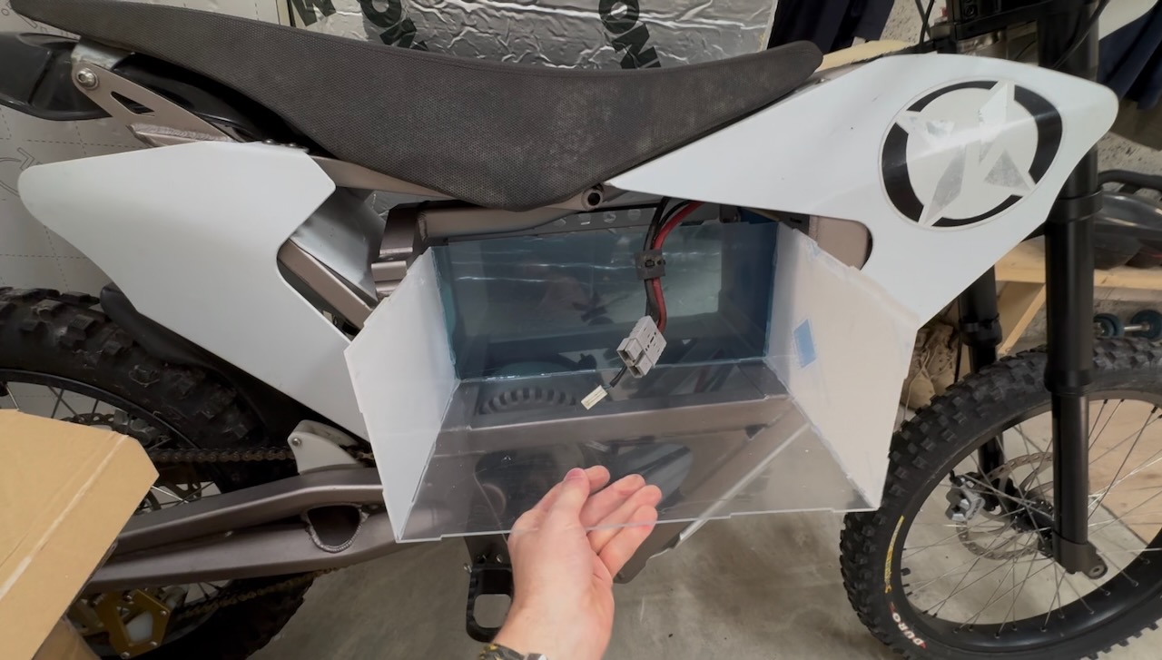
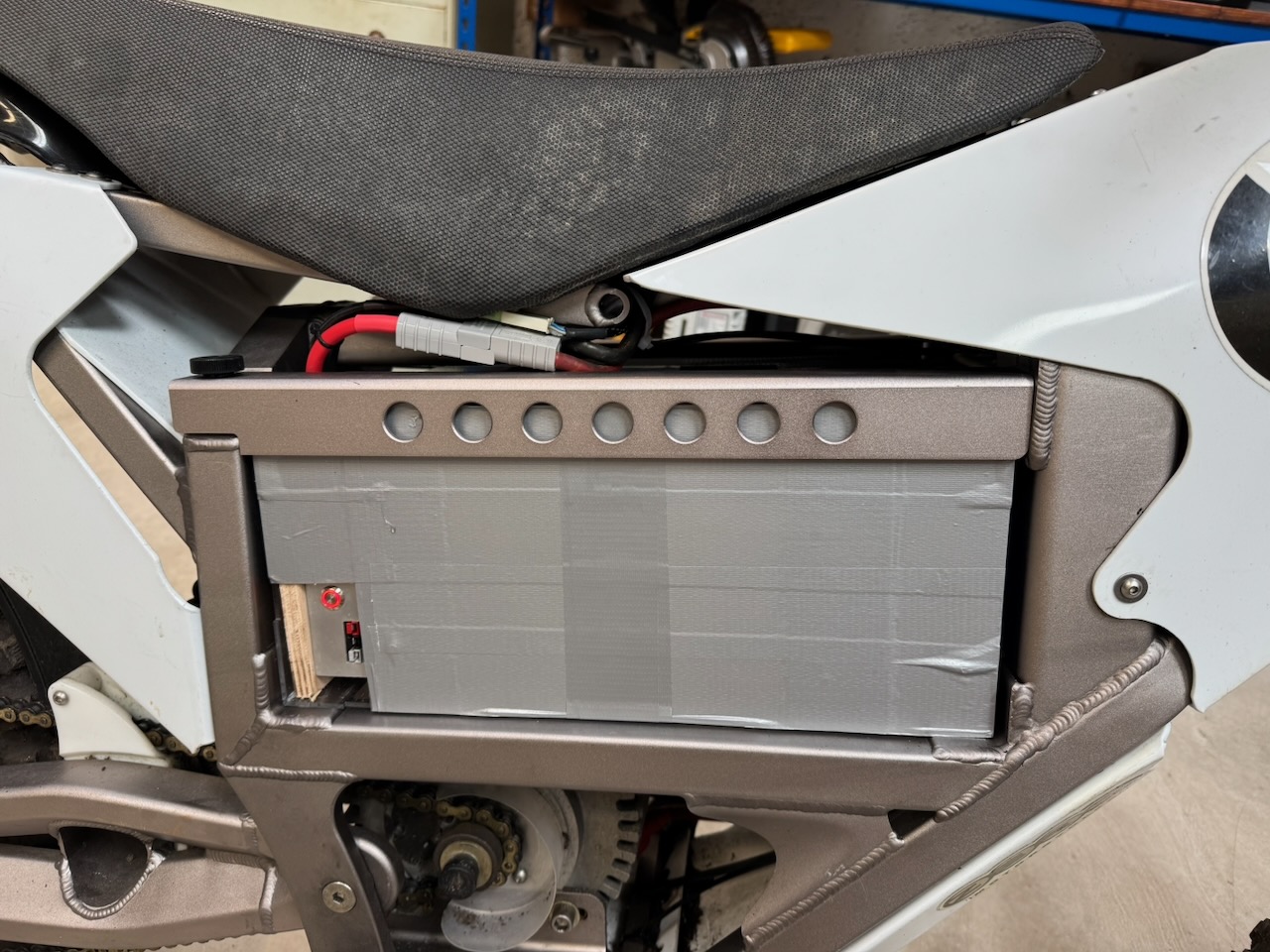
The project was “completed” (?) with a laser cut acrylic outer enclosure and a generous wrapping of duct tape.
And did the bike run? Find out in part 2…
Leave a Reply