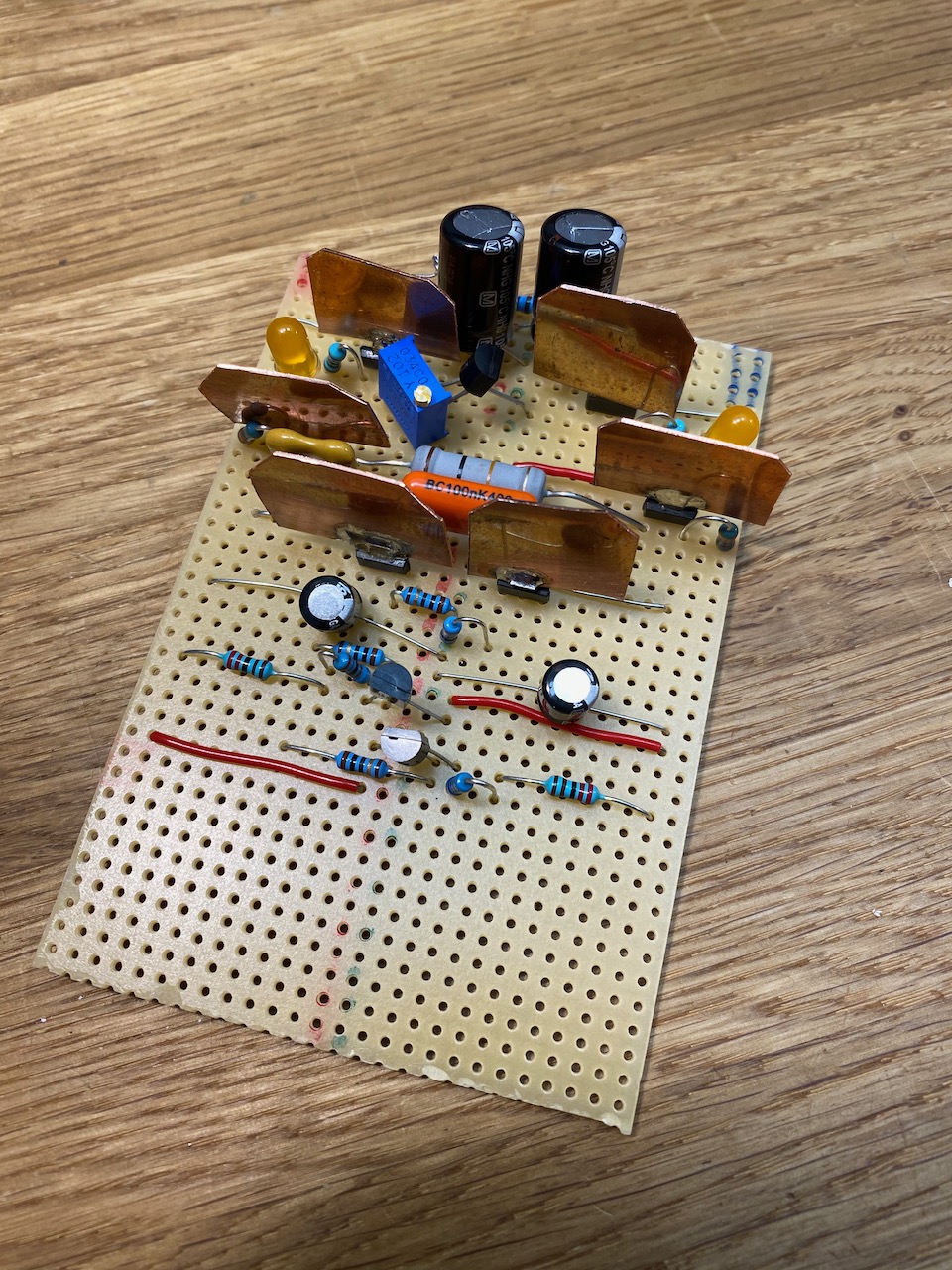
I was so excited (honestly 8) ) about the idea of a PG508-based audio amp that I decided to try building it in real life.
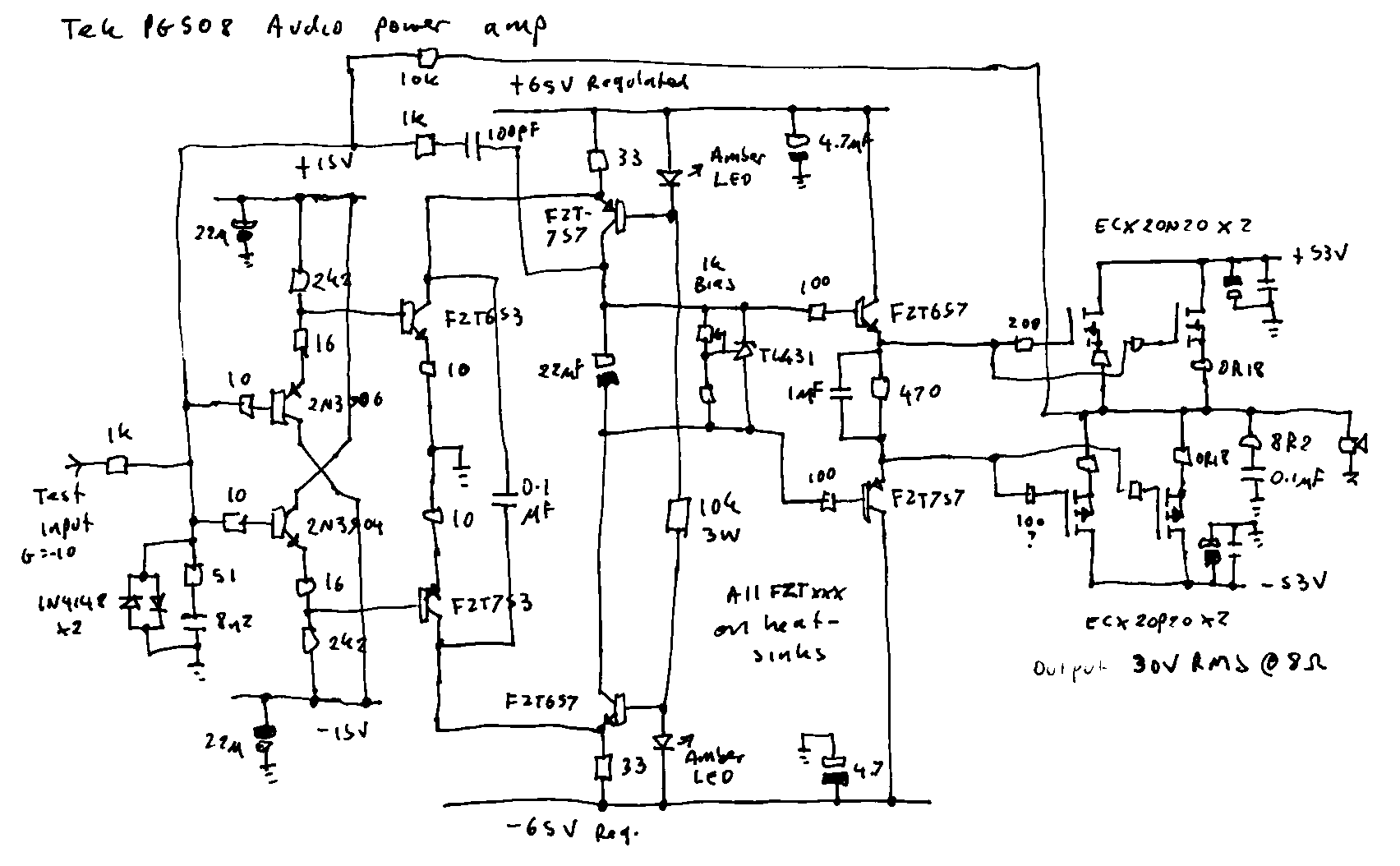
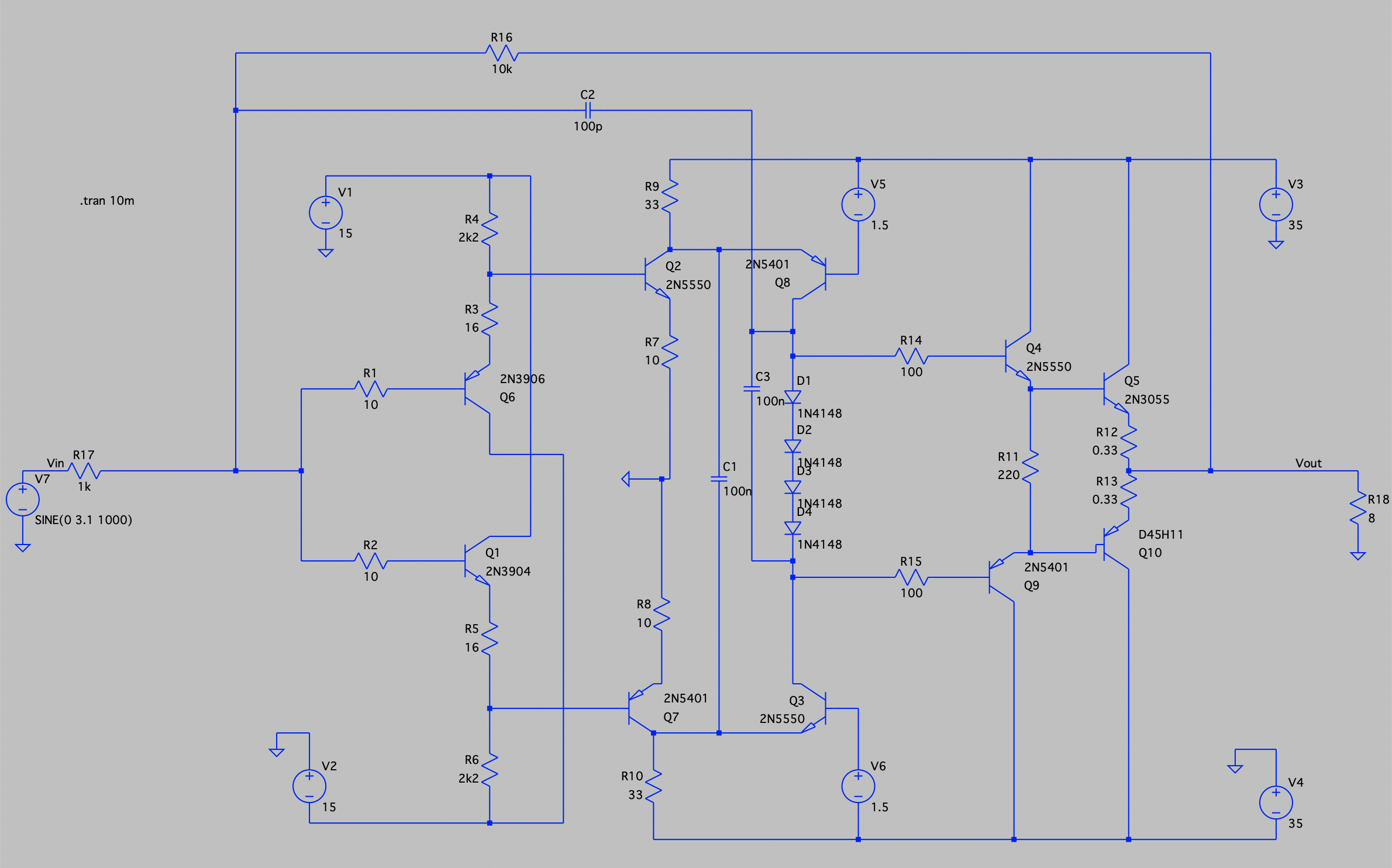
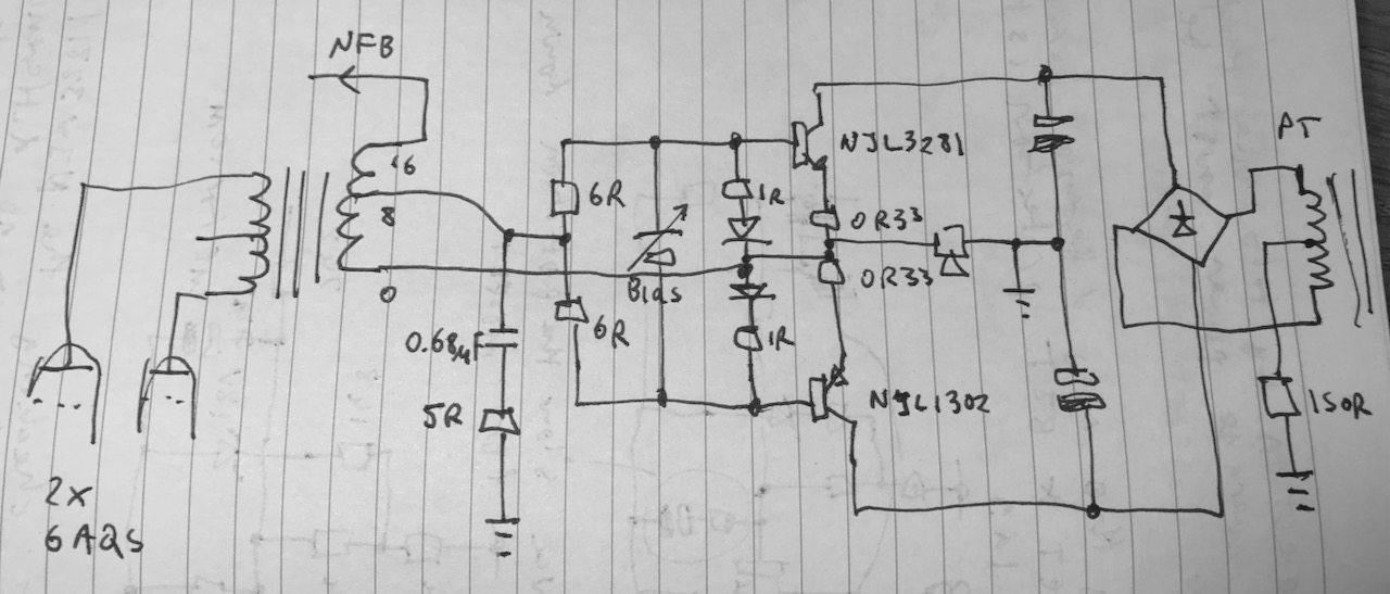
I first tested the driver circuit with +-15V supplies, no output stage and pure dominant pole compensation. It oscillated happily at 6MHz, and to get it stable I had to go back to the original PG508 lag compensation network (the 51 ohm and 8n2) The back-to-back diodes helped the clipping behaviour: without them you can reverse bias the cascode transistors and burn out the LEDs if you really overdrive it.
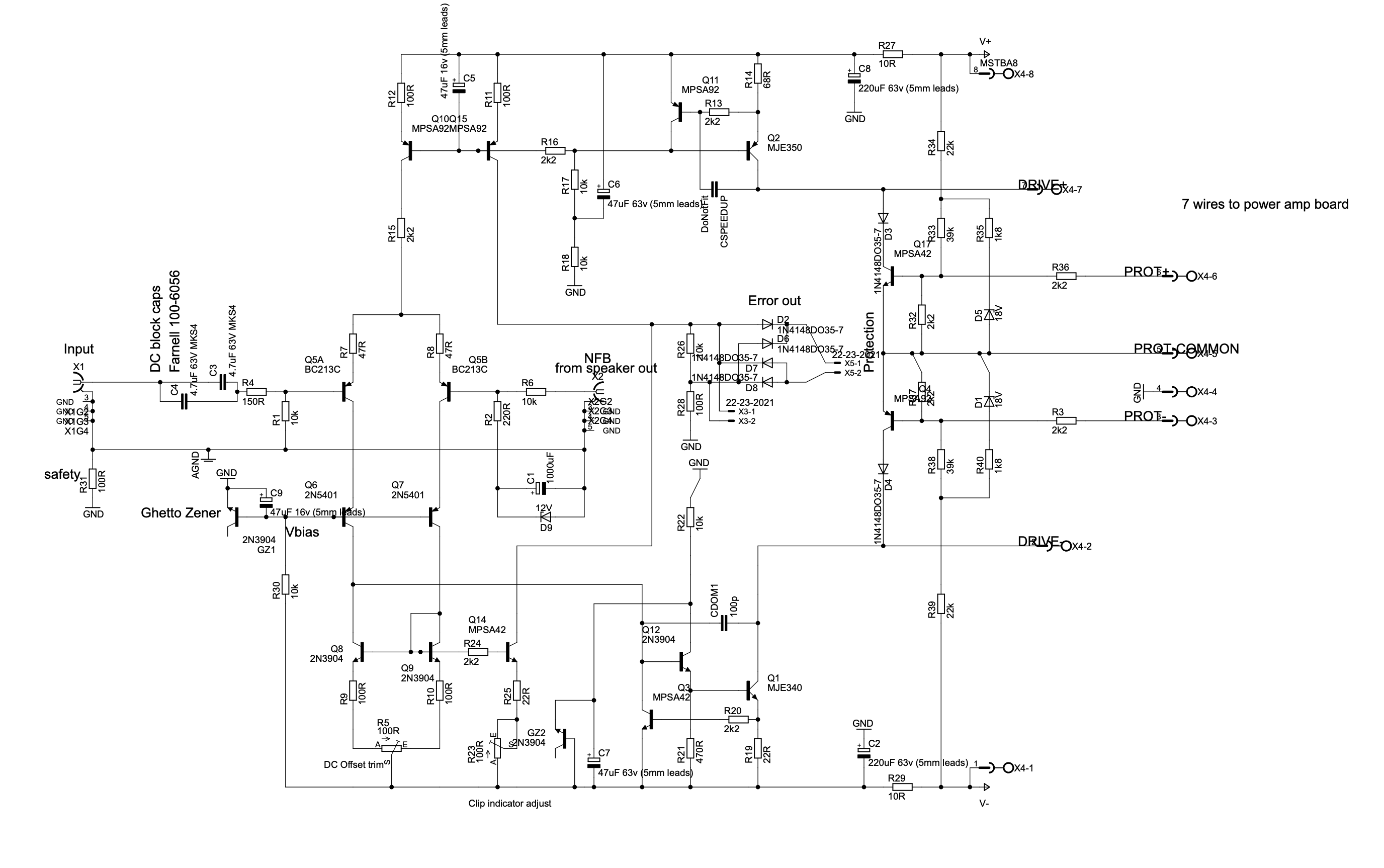
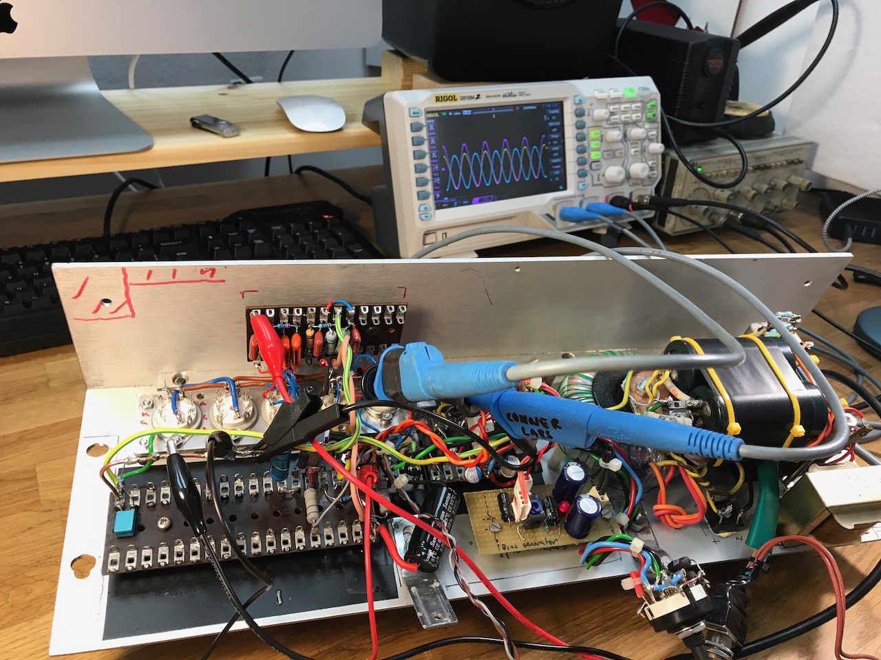
In the interest of getting something working quickly, I hooked it up to the output stage and power supplies of my ancient and long-suffering Ice Block amp, which conveniently happened to be partly dismantled with one driver board missing. It provides regulated +-65V and +-15V rails in addition to the main +-53V, so no worries about PSRR for the time being.
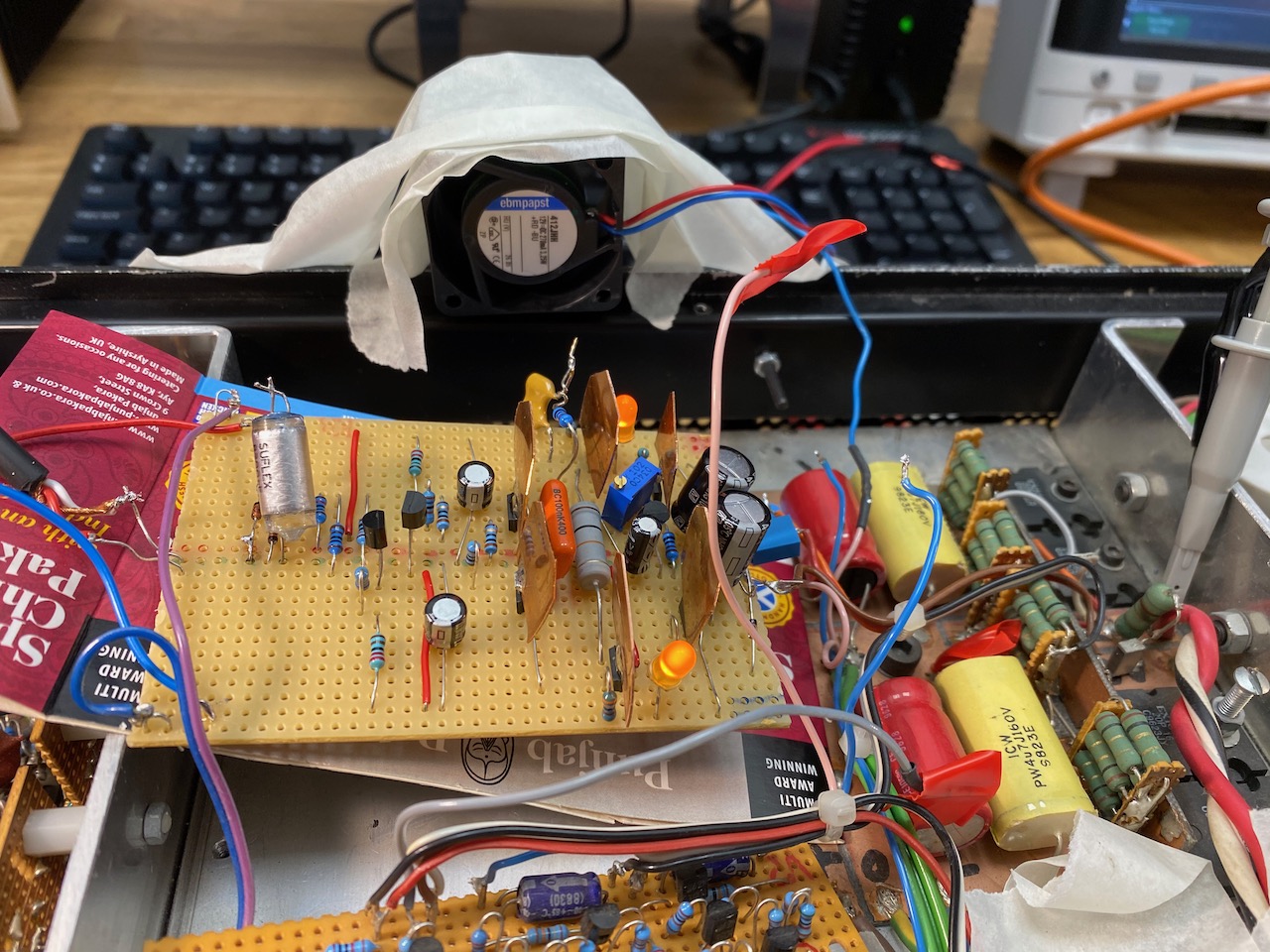
To achieve stability with the Ice Block’s hefty lateral MOSFET output stage in the loop (2 pairs of double die Exicon FETs) I had to use both the original PG508 compensation and dominant pole compensation with an extra zero (the 1k and 100pF).
I think it’s a bit temperamental because there are 3 transistor stages in the loop enclosed by the dominant pole capacitor. The Douglas Self Blameless only has 2, and my previous attempts at adding a third stage to that (cascode connection of Cdom) also caused oscillations at a few MHz.
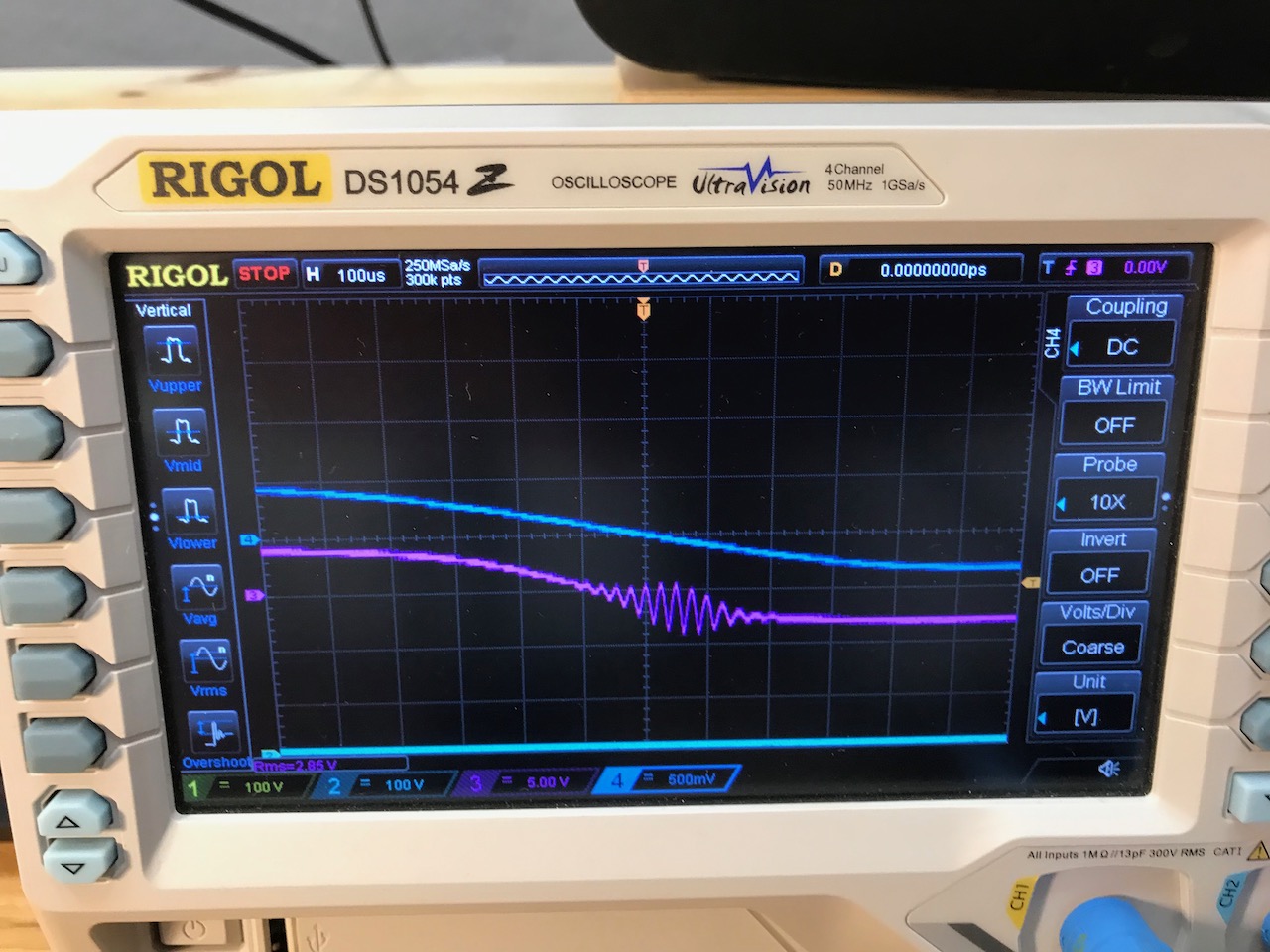
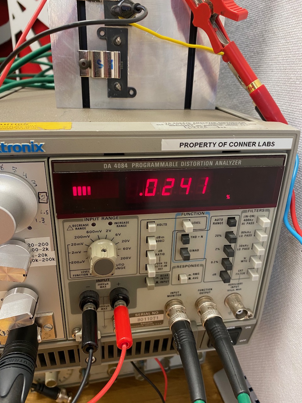
As with any half decent solid-state amp, THD+N was at the limit of my measurement system at 1kHz, and dominated by noise. I had to go to full power at 10kHz to see a meaningful distortion residual.
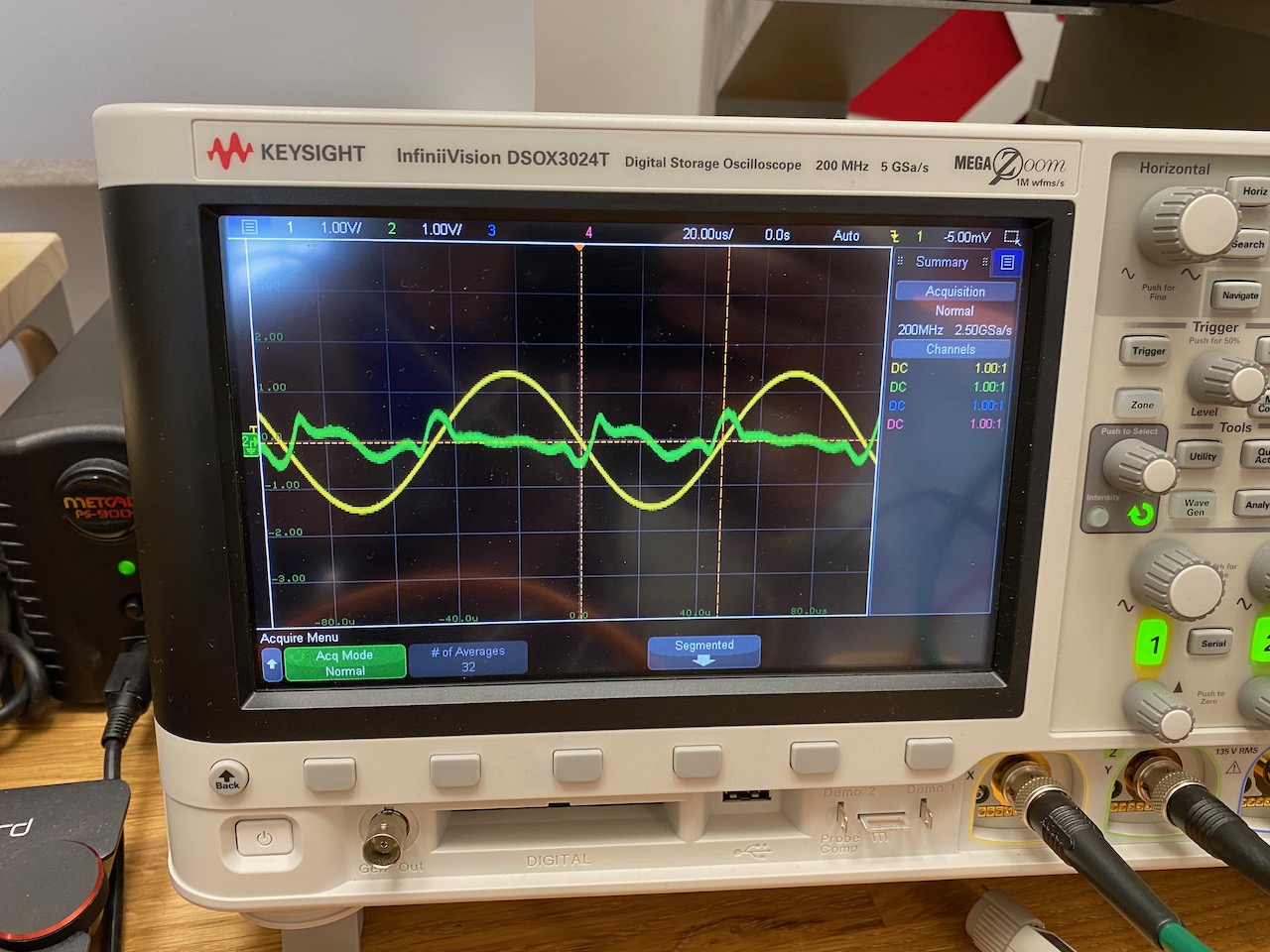
The distortion appears to be what Douglas Self called “gm-doubling”: in a push-pull circuit the gain is higher when both halves of the circuit are contributing, than when one half is cut off. And in the residual we see small lumps corresponding to increased gain around the zero crossings. I’m not entirely sure what part of the circuit is causing it. It may be the output stage, as that’s the usual culprit. It looks like it wants less bias, but the bias pot won’t go down any further. (Got to replace that TL431 with a TLV431)
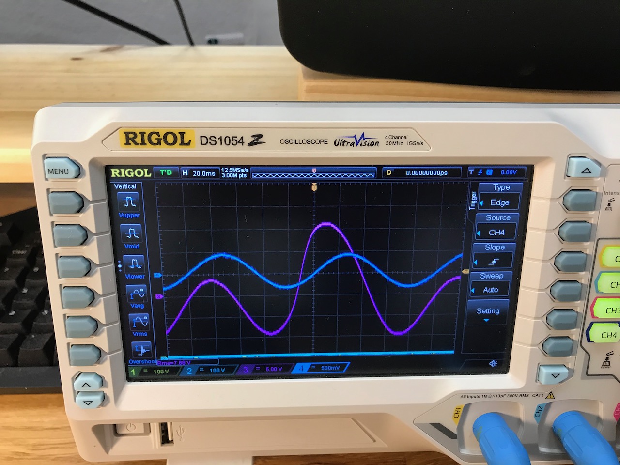
I also tested the full power bandwidth, and it happily delivers 100W to 100kHz and beyond. I didn’t push it beyond 130kHz for fear of burning out the Zobel network.
A reading of 0.025% at 100W and 10kHz, with no filters engaged, is not to be sneezed at. I’d be perfectly happy with it, except the other un-hacked channel of the Ice Block does 0.009%! The PG508 circuit has some way to go before it can beat the original Alexander CFB.
While I had the equipment out, I also tried measuring distortion with a LF411 in place of the SSM2131 in the Alexander circuit. It made no noticeable difference at any power level, even though I’d persuaded myself that the LF411 sounded bad…