[~A tale of weird waveforms~]
My main motivation for borrowing Lister was to run the welder at Container Labs. My GYS Protig 201 AC/DC claims to be “generator friendly and protected” but also “minimum generator size 7.5kVA”.
Lister is rated for 3kW at power factor 1.0, but looks massively overbuilt, so I thought it would be worth a try.
My first attempt at welding was pretty anticlimactic, on striking an arc the welder instantly shut down with error code “US1”. According to the GYS manual this means input voltage over 265V RMS. On further reading the unit claims to withstand up to 400V RMS/700V peak without damage but will apparently shut down above 265.
Since the welder has a PFC front end, I tried substituting the Odin PFC to see if this would manifest the same issue. It is rated to run at 415V RMS and has 1200V semiconductors so I had no worries about blowing it up with overvoltage. I used the Tesla Model 3 cabin heater as a dummy load for the PFC output.
This was somewhat inconclusive as the Odin PFC happily ate all of the generator output, showing no signs of serious instability under load, and making an impressive blast of hot air from the cabin heater.
The unloaded peak voltage did look somewhat high, due to the PFC’s EMI filter capacitors resonating with the generator winding inductance at the tooth ripple frequency.
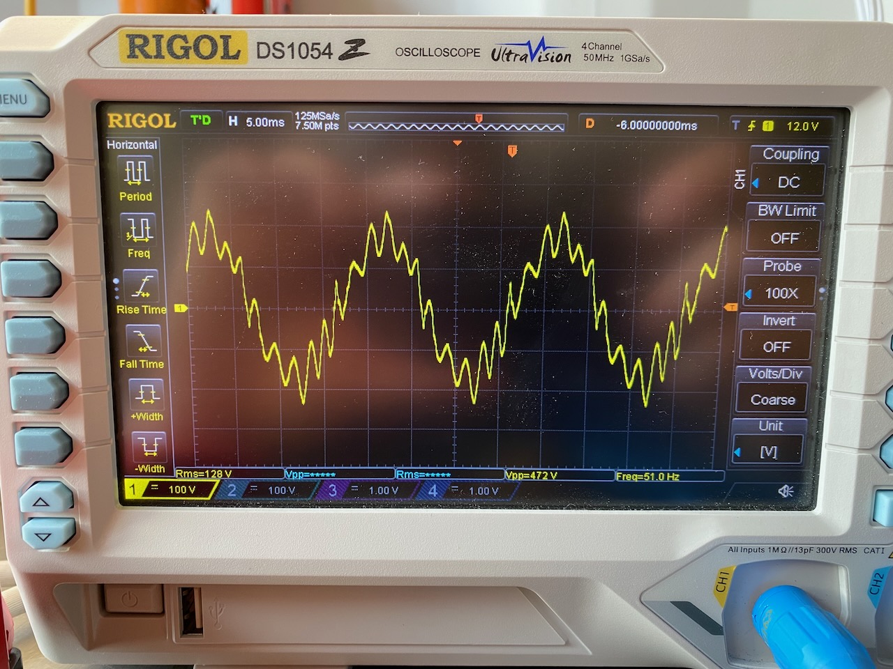
These scope shots only show one-half of the generator output voltage, as I didn’t have an isolated scope probe handy, and the generator output is centre tapped to earth. So the total peak voltage is 472V unloaded and 368V under full load. These would equate to 335V and 261V RMS with an ideal sine wave. Since the actual RMS is 256V unloaded and 232V loaded, we certainly have some evidence of waveform distortion under both conditions.
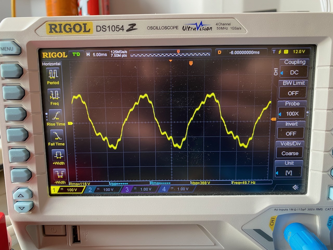
So on the face of it I could see how this could trip the welder’s overvoltage protection. I also heard from a friend who had experience of using similar generators to power his ham radio field day stations, and he said the waveforms tended to be “thin” with too high peak voltage for their RMS.
I pondered various ways of attacking the problem, a filter to remove the tooth ripple? This would need some seriously expensive and bulky inductors, so I didn’t bother. My first experiment was to step the output voltage down using an autotransformer (as I had one handy) and clip the peaks off using a rectifier, capacitor and resistive load.
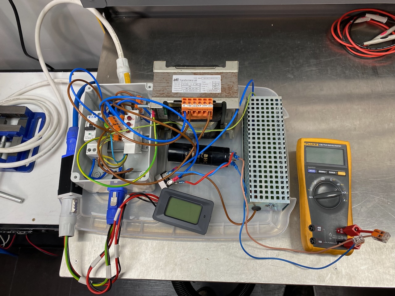
This contraption (which I’ll call the Happy Welder 3000) worked surprisingly well, using the 190V tap, the peak and RMS voltages were both brought somewhat under control, and I was able to crank the welder to about 150A output at which point the engine began to bog down and belch black smoke, but would recover by letting off the TIG foot pedal.
The Happy Welder 3000 seemed like a bodge so I went looking for a more elegant solution. I discovered that just switching the generator to 115V would give a decent result with no extra hardware needed. Voltage drop in the 25m x 2.5 sq mm extension cord (used to get generator noise and diesel fumes away from me) now limited me to a somewhat lower welding current before I got error “US2”, undervoltage this time. I was able to do a small job on mild steel this way.
I spent way too long thinking about this problem and ended up building an AVR which to my surprise, made the problem even worse! The welder was quite happy with 200V from the autotransformer, but with generator output reduced to 200V by the AVR, it wouldn’t run for more than a fraction of a second before tripping on error US1.
I don’t know how it took me so long, but I eventually stumbled on the idea of filming the scope screen while welding and examining the footage frame by frame.
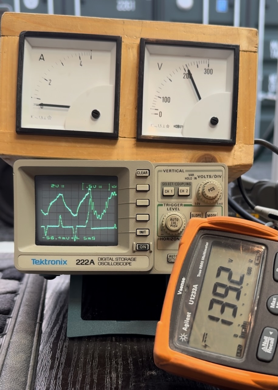
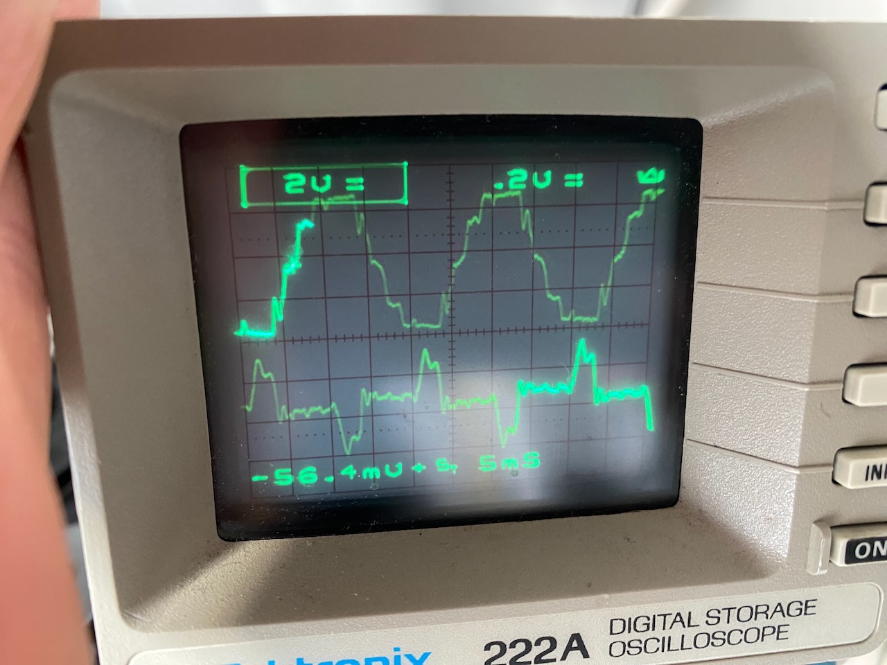
I believe this frame captures the instant that the welder shuts down on error US1. Top trace is generator output voltage, bottom is current drawn by the AVR’s peak clipping channel. DVM shows the voltage across the AVR’s filter capacitor, which should be one-half of the peak output voltage.
The waveform is completely different to any I saw previously, and leaves only one possible explanation, the impedance (resistance and inductance) of the generator windings is too high for the welder’s PFC front end, it goes unstable and wrenches the waveform out of shape.
The instability pushes the peak voltage way higher than anything I measured while not welding, and does this so quickly that the meters I’d been using didn’t have time to register it. The AVR’s peak clipper tries to keep the peak voltage under control but fails.
This explains why stepping the voltage down to 200, and switching the generator to 115V, both worked and enabled me to weld, but using the AVR to reduce the voltage to 200 didn’t.
Switching to 115V gives an impedance one-quarter of the 230V setting. A transformer that steps the voltage down from 240 to 200 reduces the impedance to 76%.
On the other hand, the AVR only compensates for relatively slow fluctuations in voltage by adjusting the field current. It has no effect on the resistance and inductance of the windings, so can’t do anything about the waveform distortion.
I think I earned my professional development points on this one.
Leave a Reply