I’m a fan of the Riden RD60xx series of power supplies. They definitely qualify as Chinesium, but a fairly high grade. They come as a small panel mounting unit that functions as a non-isolated buck converter. Riden also sell cases for them and a few different switchmode power supplies to feed the module with bulk DC.
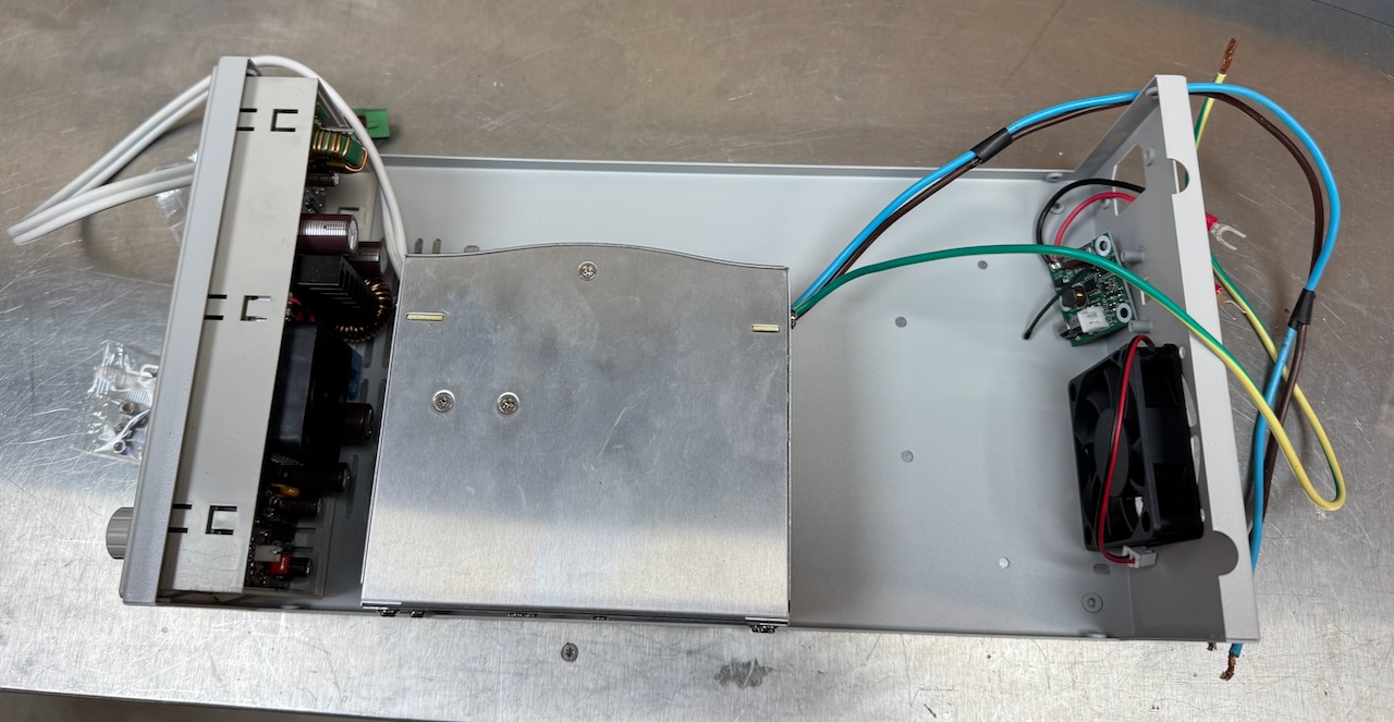
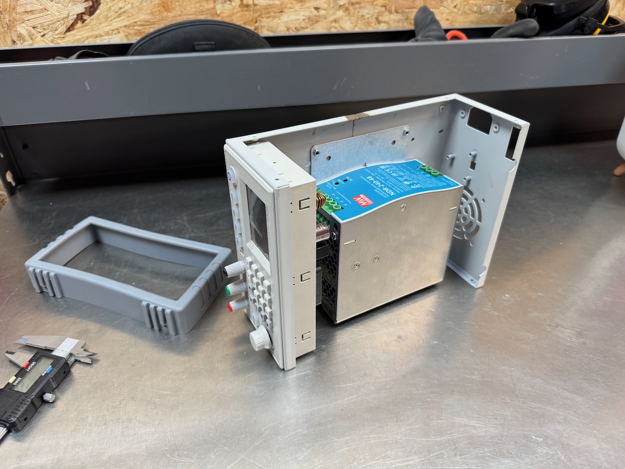
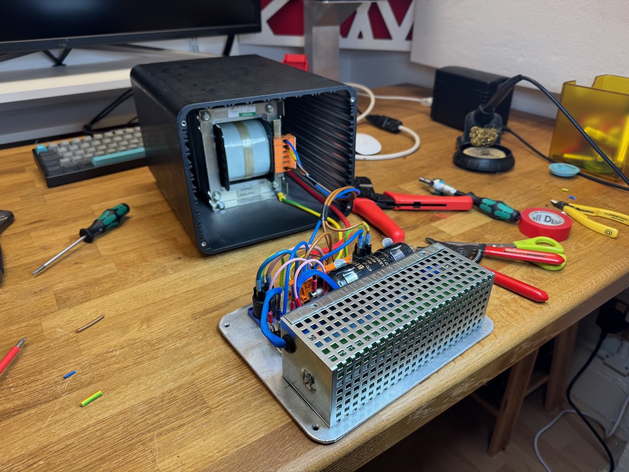
To build this one I used the RD6006P module, a 60V/6A version that claims to have a linear post-regulator for low noise, paired with a Meanwell NDR-240-48 switchmode power supply. This came from CPC, and all the other parts were sourced from AliExpress.
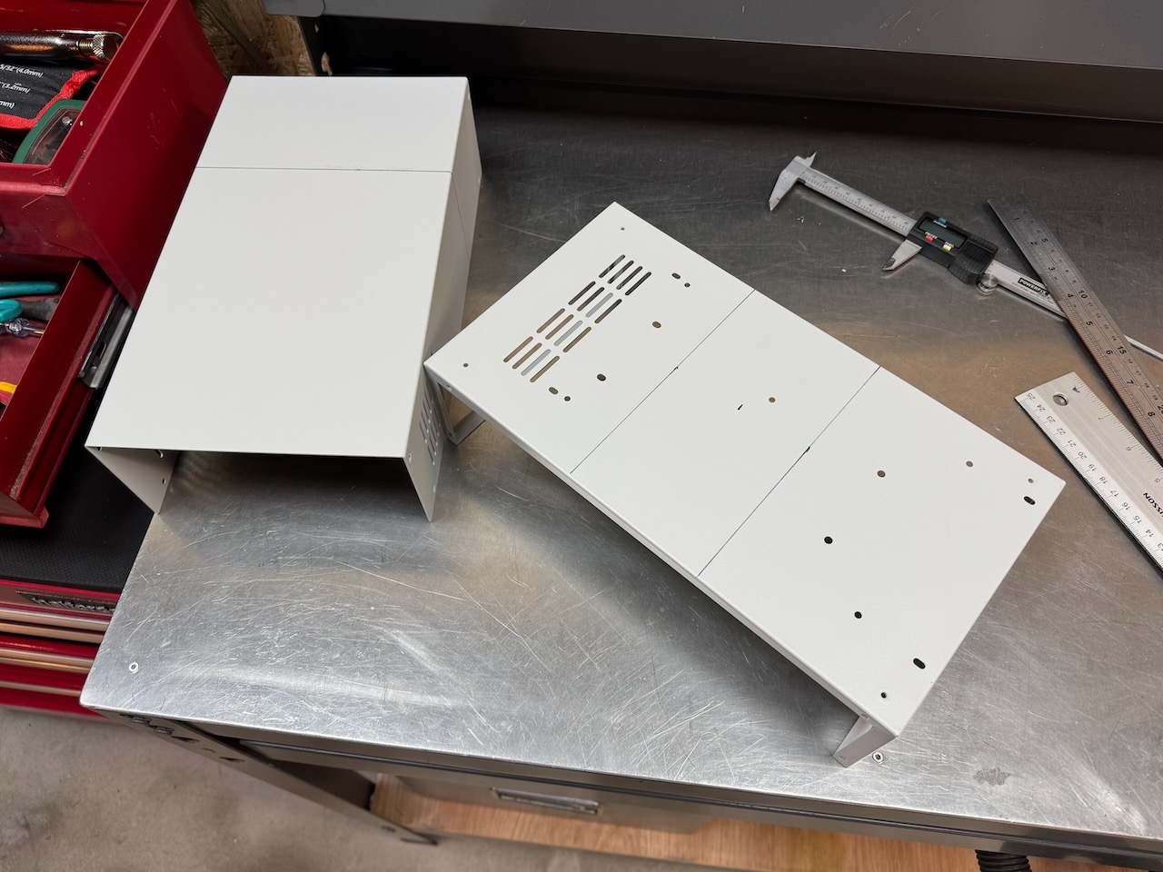
The official Riden case is designed to fit their largest bulk power supply, the 1440W that ships with the RD6024. The 240W Meanwell PSU is much smaller…
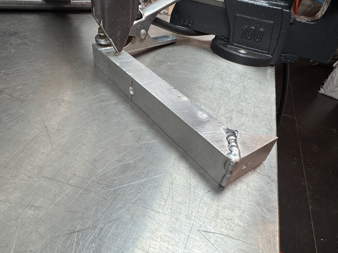
Let’s cut and shut it a little 🙂
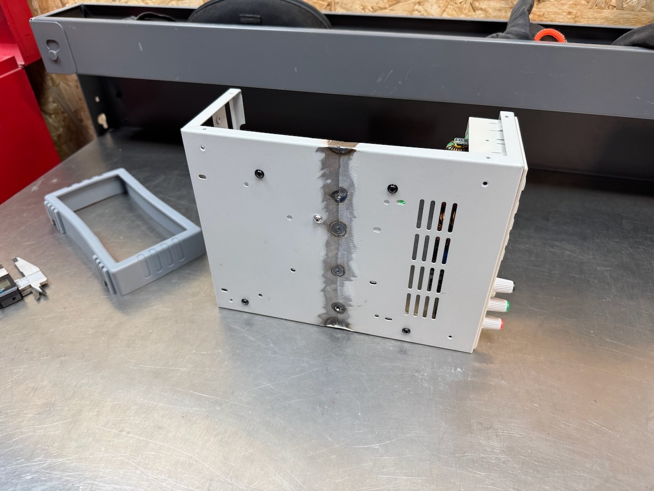
What an impressive scar, Dr. Frankenstein would be proud. I tried to limit the heat input as much as possible but the thin steel still warped horribly, so I gave up after a few tack welds.
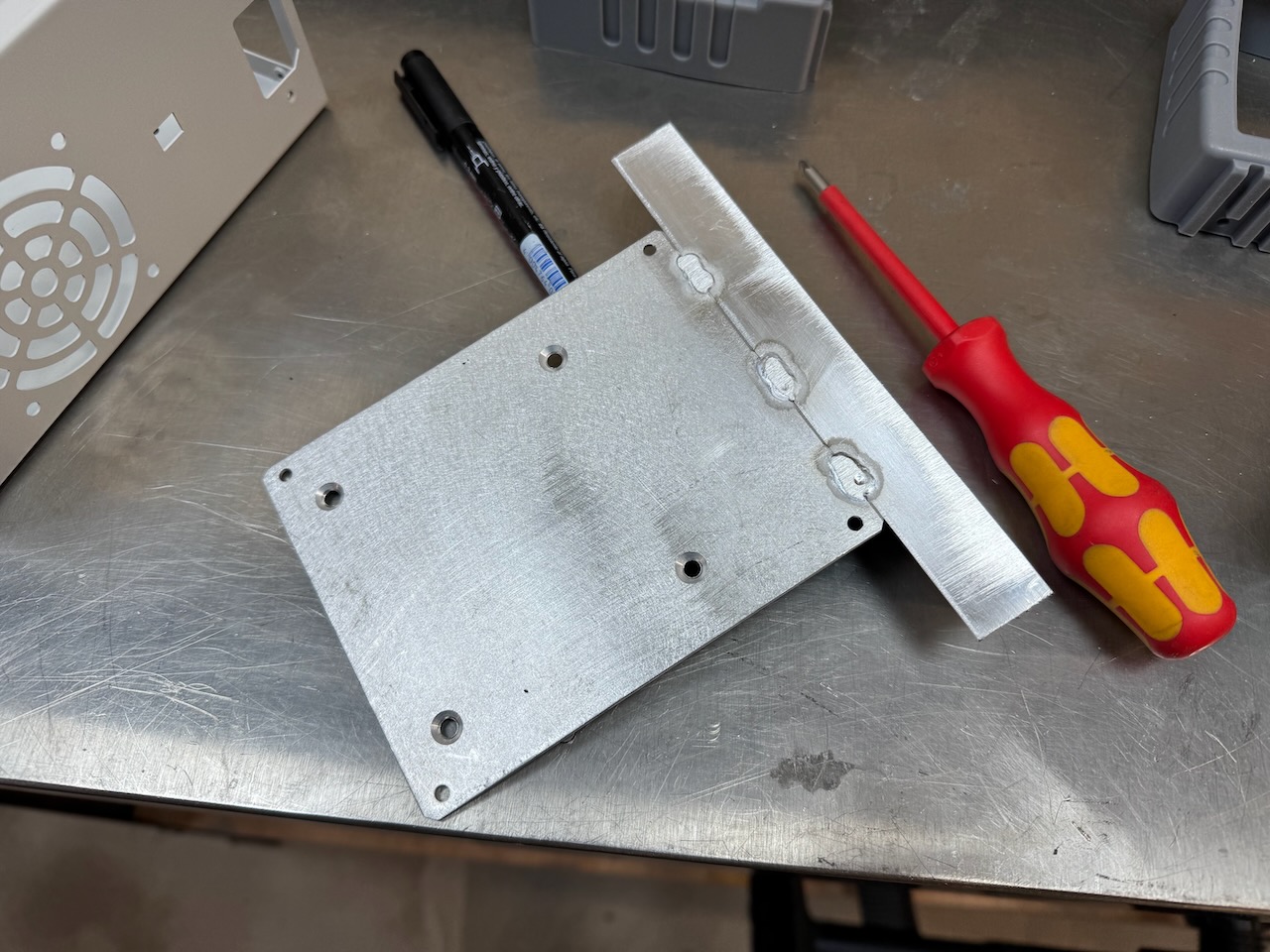
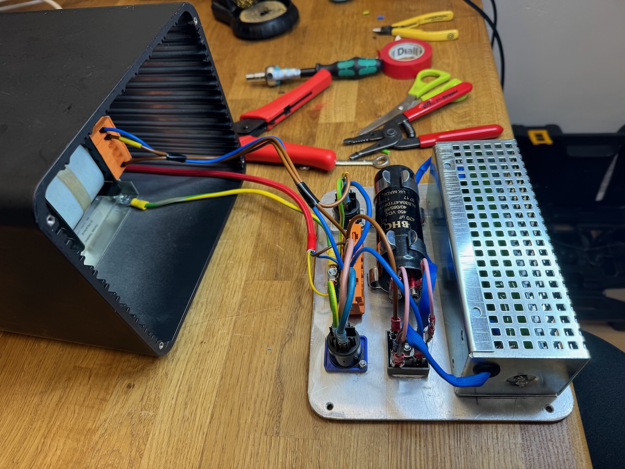
A bracket was made out of surplus aluminium sheet and angle to hold the PSU in place and handily also straighten out the warped casing a bit.
The Meanwell fits with room to spare, I think I could have cut the case even shorter.
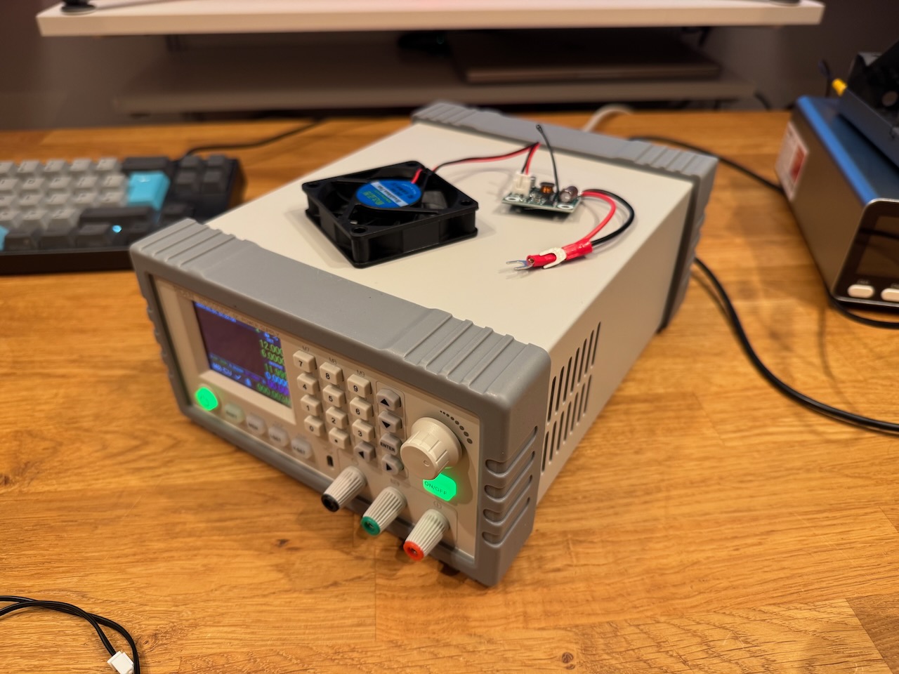
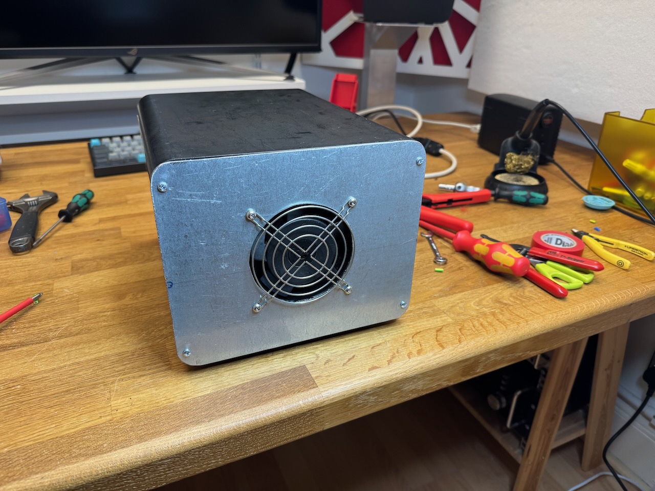
It worked, and I’ll install the fan kit another day 🙂
This was a long-running project to get my welder running off the Lister diesel generator. After a few dead ends it is now officially finished and has become a piece of workshop equipment for day-to-day welding of other things.
It ended up split into two sections which I’ll call the Happy Welder 3000S and 3000T. The division was a bit arbitrary and was really about letting me reuse salvaged enclosures from my junk heap.
Happy Welder 3000S
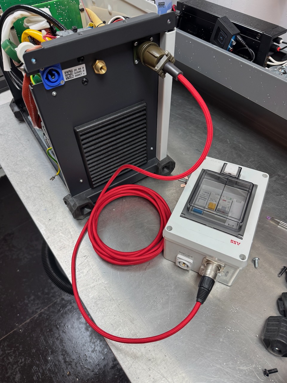
The “S” stands for switch box or splitter. The main purpose of this part is to split the incoming supply from the generator into two. One feed goes to the welder and the other to a selection of “dumpable loads” which are switched off while welding is in progress.
The motivation behind this is to keep a decent amount of load on the engine most of the time. Diesels like to work and will get clogged up with soot if left idling for long periods of time. And the nature of welding is short periods of high power draw with long breaks in between. (at least at Container Labs it is, I’m not planning on building a ship any time soon)
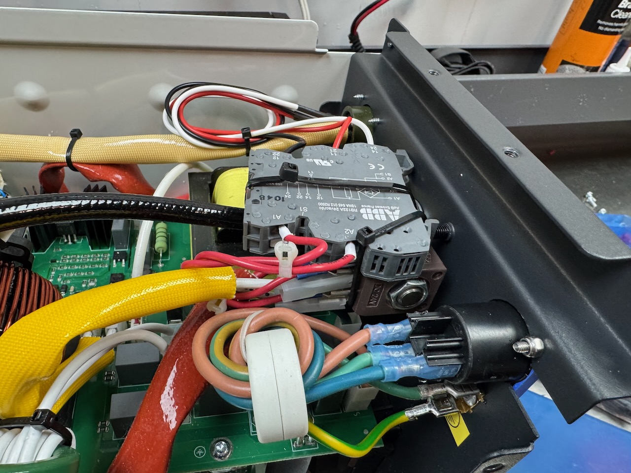
I fiddled with a few different schemes to turn off the dumpable loads by sensing the supply current draw of the welder, but couldn’t get this to work reliably. So I modified the welder slightly. It has a solenoid operated gas valve inside that supplies argon to the torch while welding. This opens a second or two before the arc is struck and stays open for about 20 seconds after it goes out. Just perfect for actuating a load dump contactor.
Using some zip ties and piggyback spade terminals, I connected a relay in parallel with the gas valve operating coil. This runs off 24V DC so finding a suitable relay was no problem. To save drilling a hole* in the welder I repurposed the 3 unused pins on the foot pedal connector. I do have a foot pedal, but it plugs into the hand controller socket on the front panel.
* another hole- the eagle-eyed might notice that I’ve already replaced the captive power cord with a Neutrik Powercon inlet. I love Powercons 😀
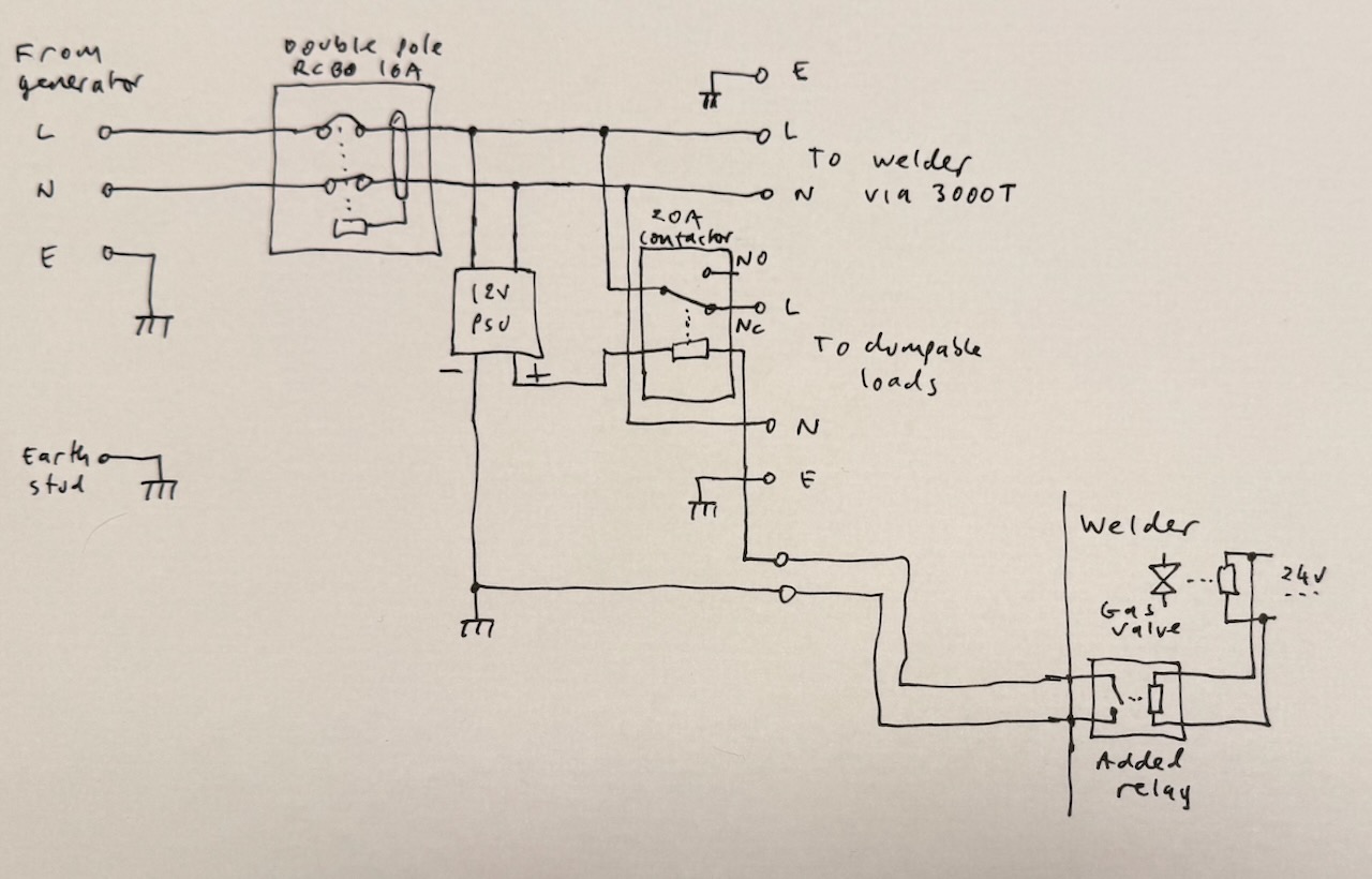
Schematic of Happy Welder 3000S
I wanted a low voltage signal for triggering the load dump contactor. The relay I added inside the welder is quite capable of switching 230V, but the foot switch plug has male pins that could deliver an electric shock when unplugged if I used mains voltage here. So the finishing touch was a small low voltage power supply inside the 3000S enclosure just for the contactor coil. I used a 12V switched mode wall wart with the pins trimmed down and a piece of plastic attached with hot glue to insulate the stumps.
The CPC catalogue turned up an inexpensive 20A contactor with a 12V coil and normally closed contact, and the 3000S was done.
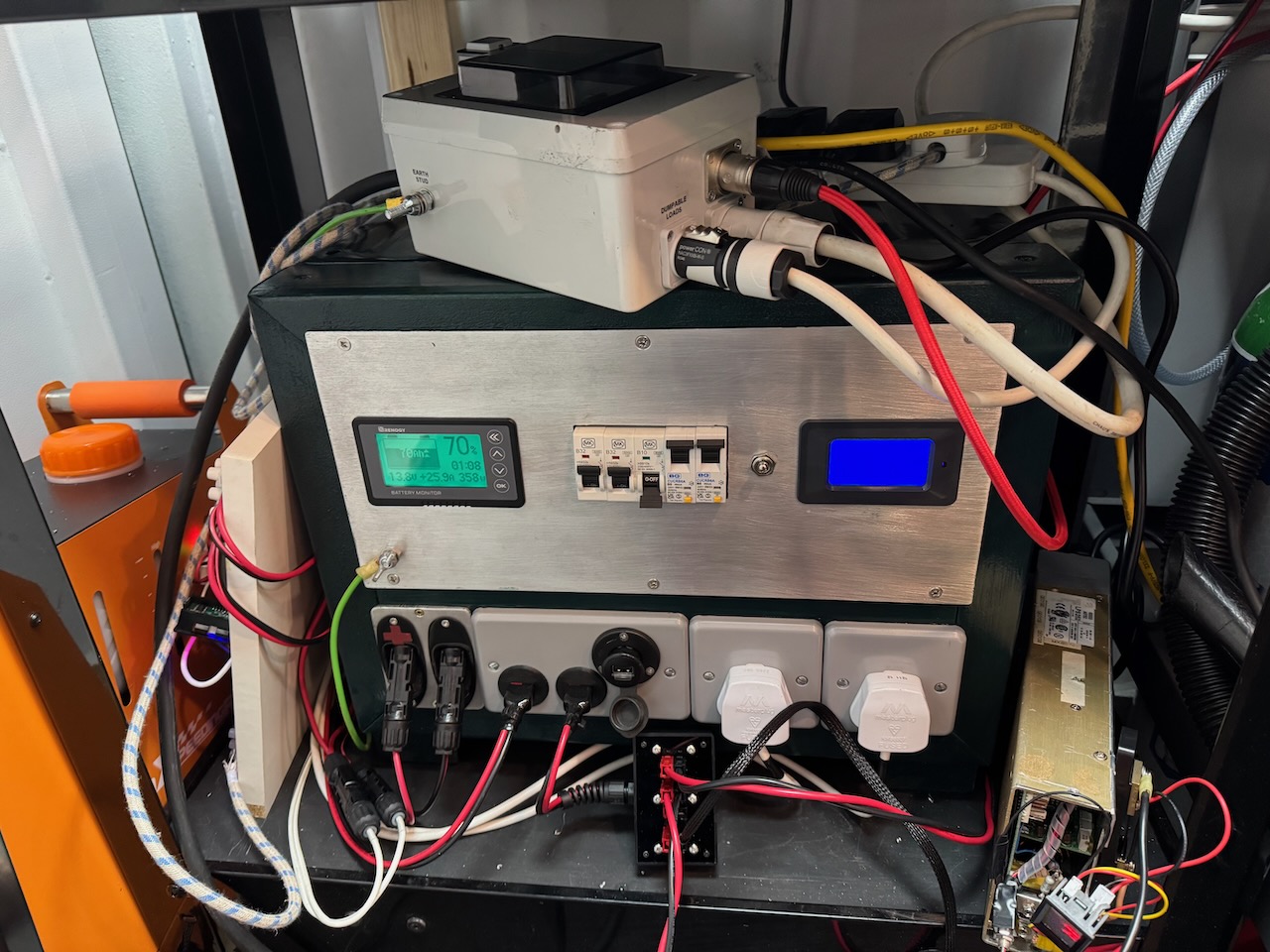
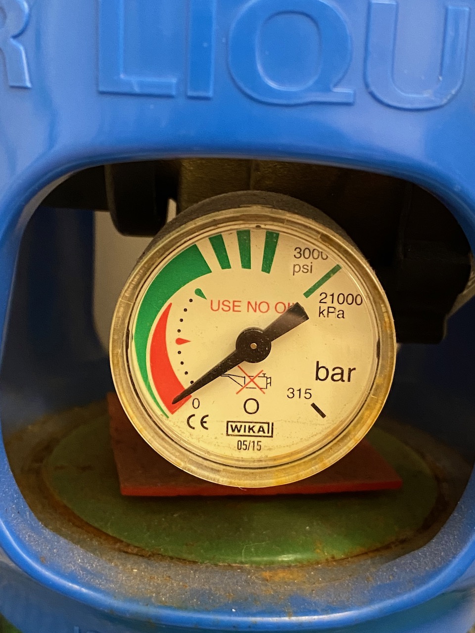
In use the “dumpable loads” are two battery chargers feeding the Power Tank, and an electric heater. The 3000S also serves as the earthing point for the generator and everything connected to it.
The battery chargers are modified switched mode power supplies which I’ll write about another time. In the bottom right you can see my long-suffering Astec LPS250 which started life as 5V, 50A, and is now cranking out 30A at 14.4V. Not bad for a “250W” unit, do I smell burning? :/
Happy Welder 3000T
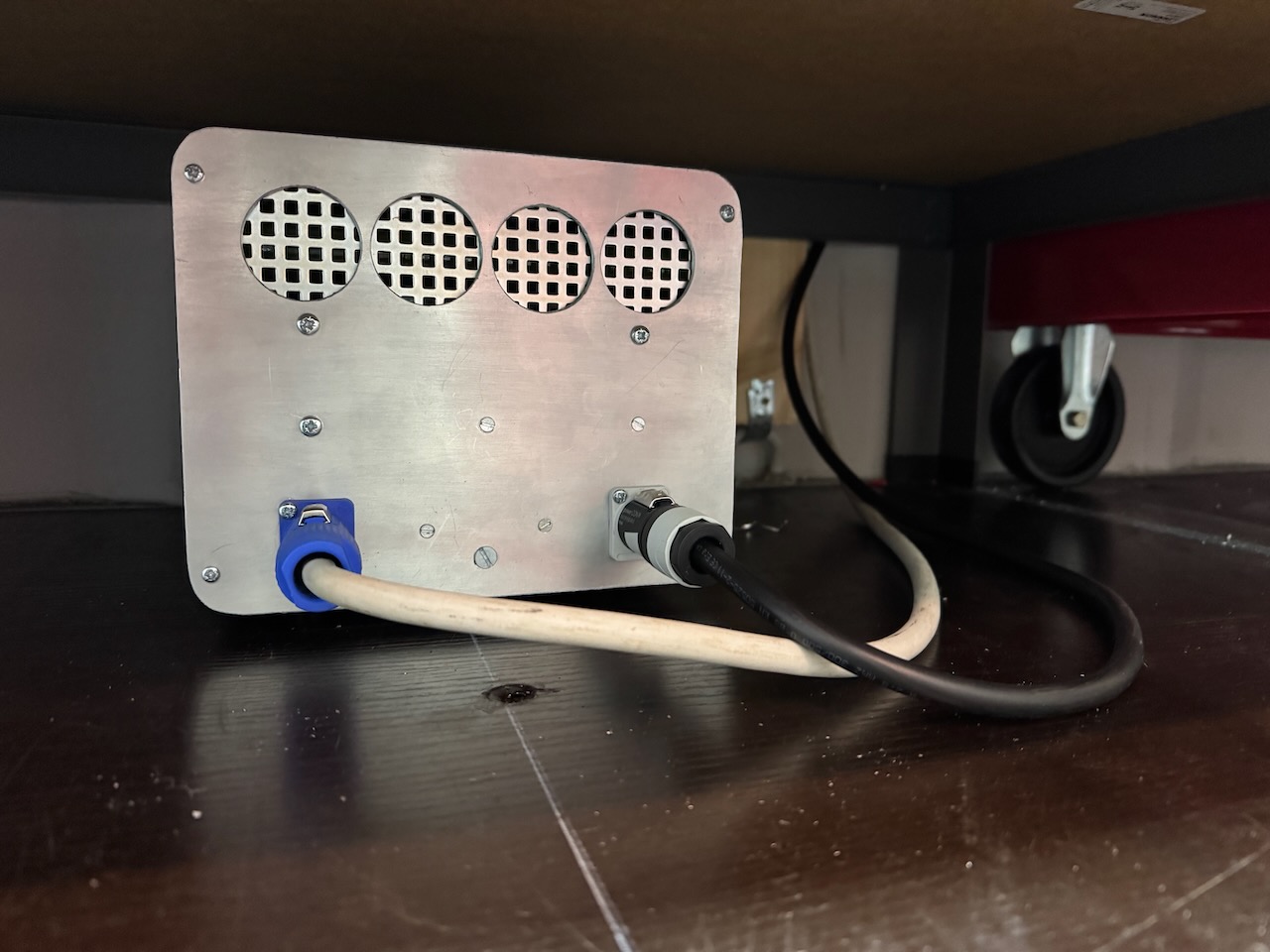
T is for transformer. This box (a Pentium 4 PC in a previous life) contains all of the parts that I found were needed to make the welder accept Lister’s quirky retro power quality. I already had this enclosure in my junk pile and it fitted perfectly under the workbench. I pondered trying to squeeze the 3000S parts in here too but decided it would be a wiring and assembly nightmare.
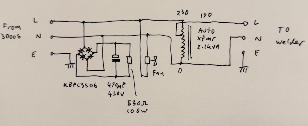
Schematic of Happy Welder 3000T
The most important part (as determined by trial and error) is a 2.1kVA autotransformer that steps down 230V to 190. I believe this was originally used to reduce the voltage to street lighting in the early hours as an energy saving measure.
The box also contains a bridge rectifier, capacitor and power resistor (sold as a 230V, 100W cabinet heater) the purpose of which is to draw lots of current on the voltage peaks and squash them down a bit further. This was the final bodge that allowed me to max out the generator’s engine power without any overvoltage trips. Hopefully it should also protect the 12V power supply inside the 3000S from destruction by excessive peak voltage.
A small fan on the rear panel blows air over the transformer, before it exits through the resistor. This is really a must as the resistor is dissipating about twice its rated power.
The fan was also salvaged. I can’t remember what it came out of. I had a fun afternoon making front and rear panels out of pieces of scrap metal.
The first of hopefully many happy welds. (proof that a weld doesn’t need to be Insta worthy to be happy 😀 )
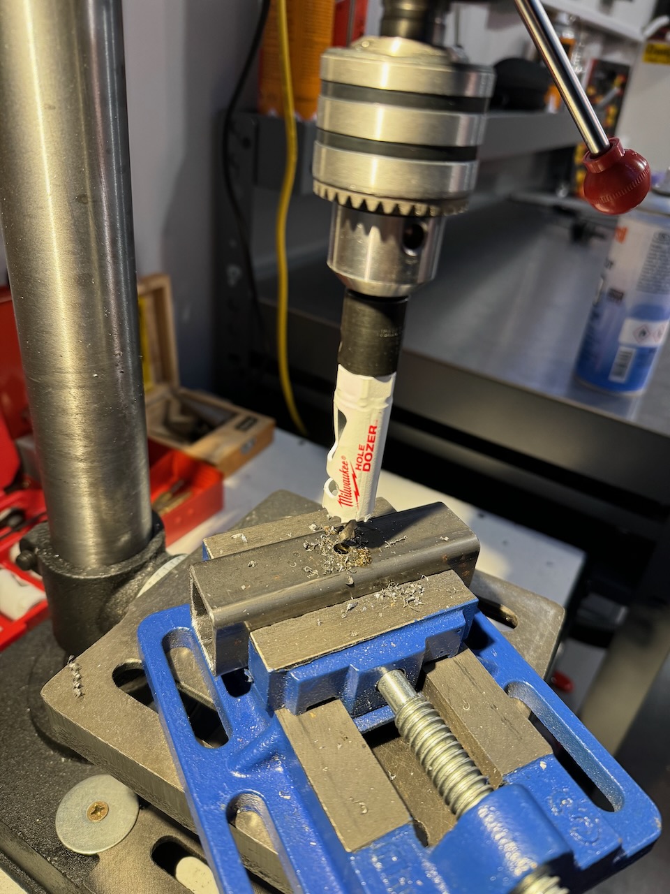
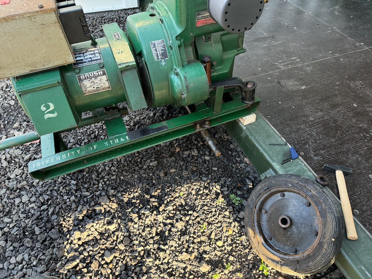
I was getting really tired of the massive flat spots on Lister’s tyres that made moving it a serious effort. I got some pneumatic tyred wheels from Machine Mart, and some 20mm round steel bar, box section, and 20mm shaft collars.
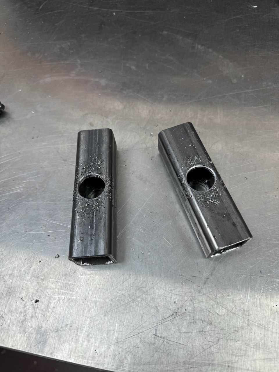
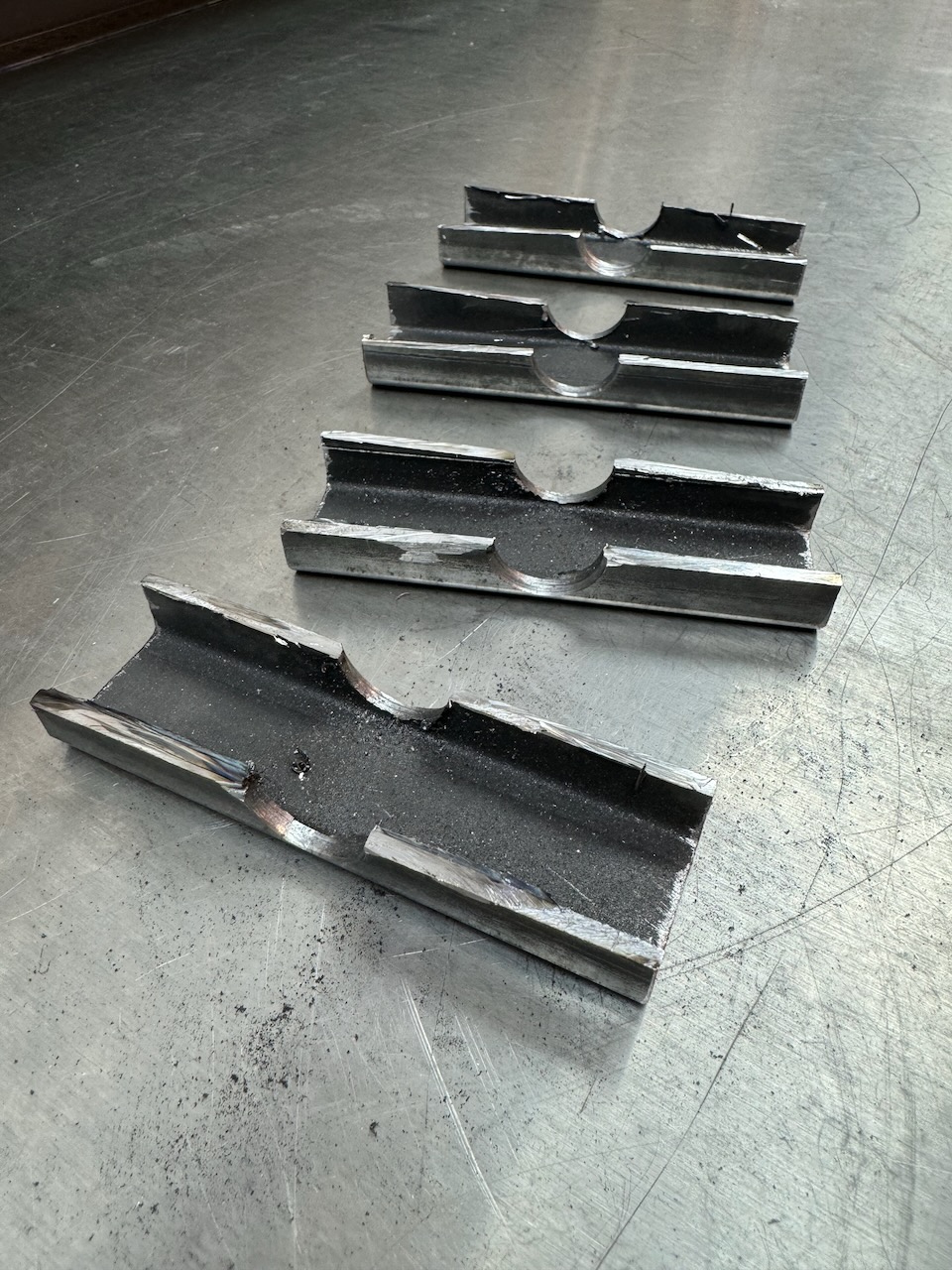
By the tender ministrations of the Milwaukee Hole Dozer and angle grinder, the box section was turned into a set of axle collars.
I was too cheap to buy precision shafting for the axles, I went for so-called “round” mild steel bar which isn’t actually all that round. A lot of grinding was involved to get the shaft collars and wheels to fit onto it.
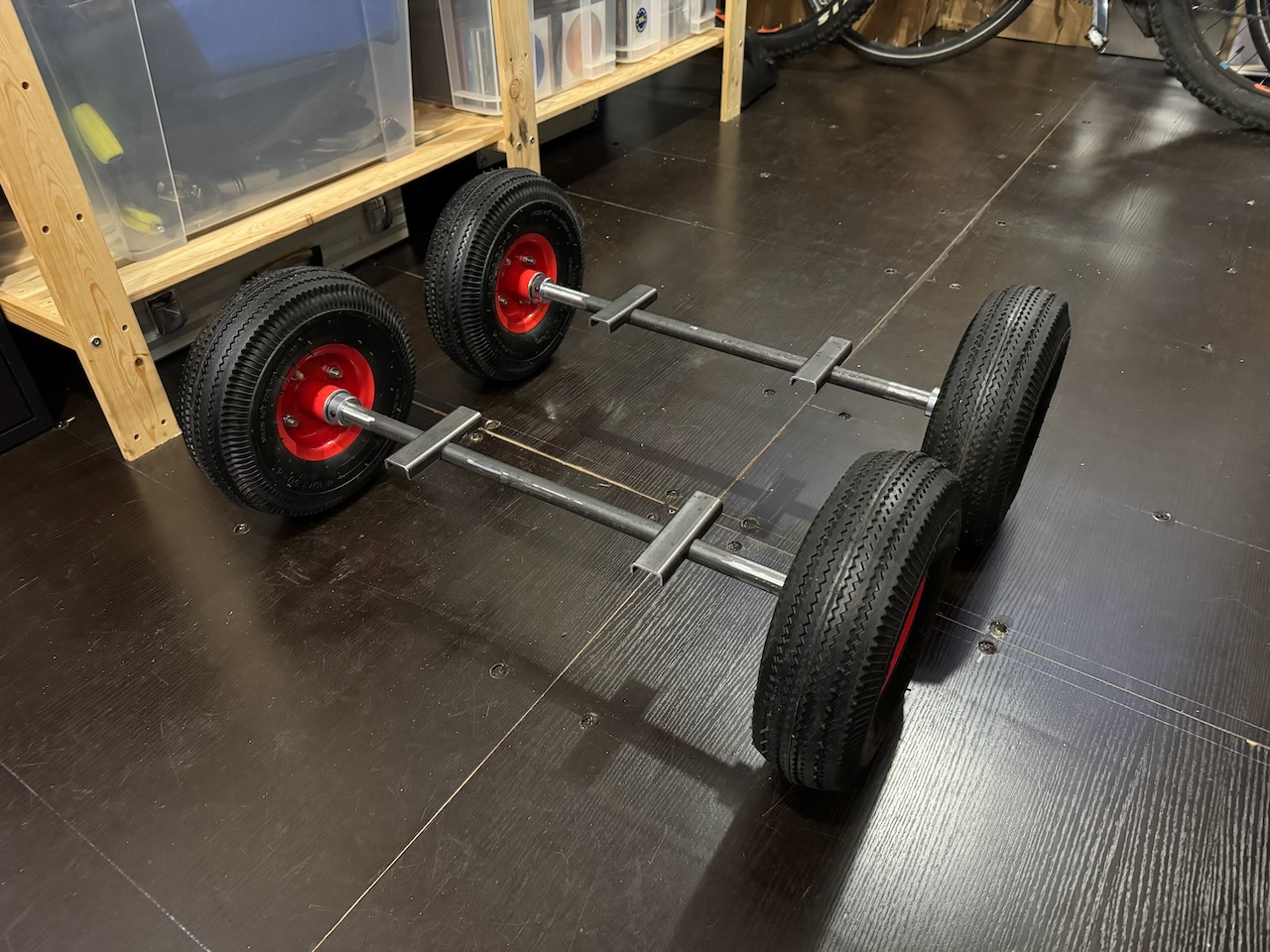
The next part was actually really fiddly and I apologise for not getting more pics of it. I had to jack the generator up, remove the existing wheels and axle, and offer up the new axles to the frame to mark out the bolt holes. As the unit is on loan, I didn’t want to drill any new holes in it, so I drilled the axle mounts to line up with the existing holes.
So far so good, but the next step was to fire up the generator and use it to weld its own axles together without having it vibrate its way off the temporary pieces of wood it was propped on.
It was getting dark and I was in a bit of a hurry as I couldn’t put the thing away and lock up until it had functioning wheels on it again. The welds turned out horrible, but as the saying goes:
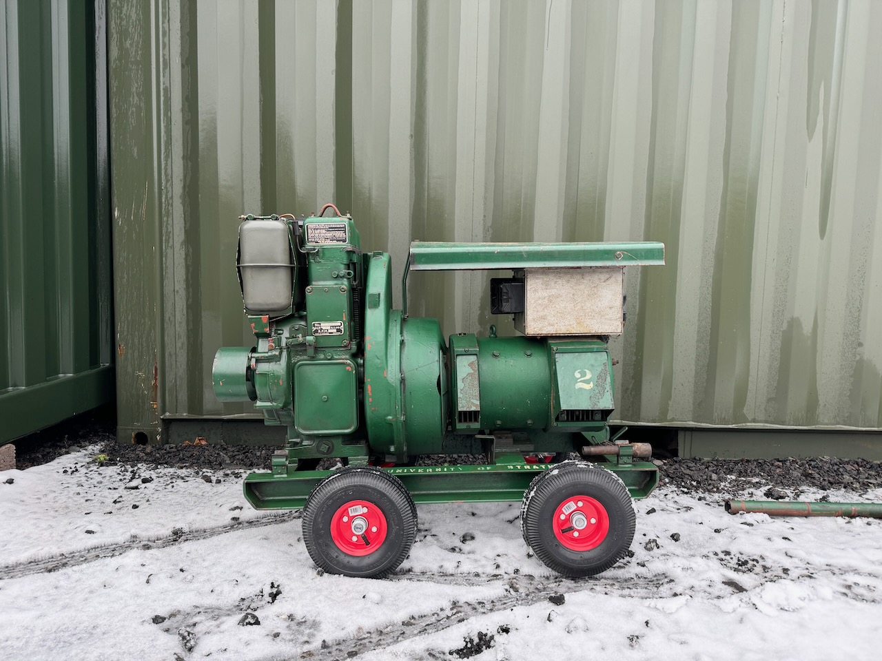
My main motivation for borrowing Lister was to run the welder at Container Labs. My GYS Protig 201 AC/DC claims to be “generator friendly and protected” but also “minimum generator size 7.5kVA”.
Lister is rated for 3kW at power factor 1.0, but looks massively overbuilt, so I thought it would be worth a try.
My first attempt at welding was pretty anticlimactic, on striking an arc the welder instantly shut down with error code “US1”. According to the GYS manual this means input voltage over 265V RMS. On further reading the unit claims to withstand up to 400V RMS/700V peak without damage but will apparently shut down above 265.
Since the welder has a PFC front end, I tried substituting the Odin PFC to see if this would manifest the same issue. It is rated to run at 415V RMS and has 1200V semiconductors so I had no worries about blowing it up with overvoltage. I used the Tesla Model 3 cabin heater as a dummy load for the PFC output.
This was somewhat inconclusive as the Odin PFC happily ate all of the generator output, showing no signs of serious instability under load, and making an impressive blast of hot air from the cabin heater.
The unloaded peak voltage did look somewhat high, due to the PFC’s EMI filter capacitors resonating with the generator winding inductance at the tooth ripple frequency.
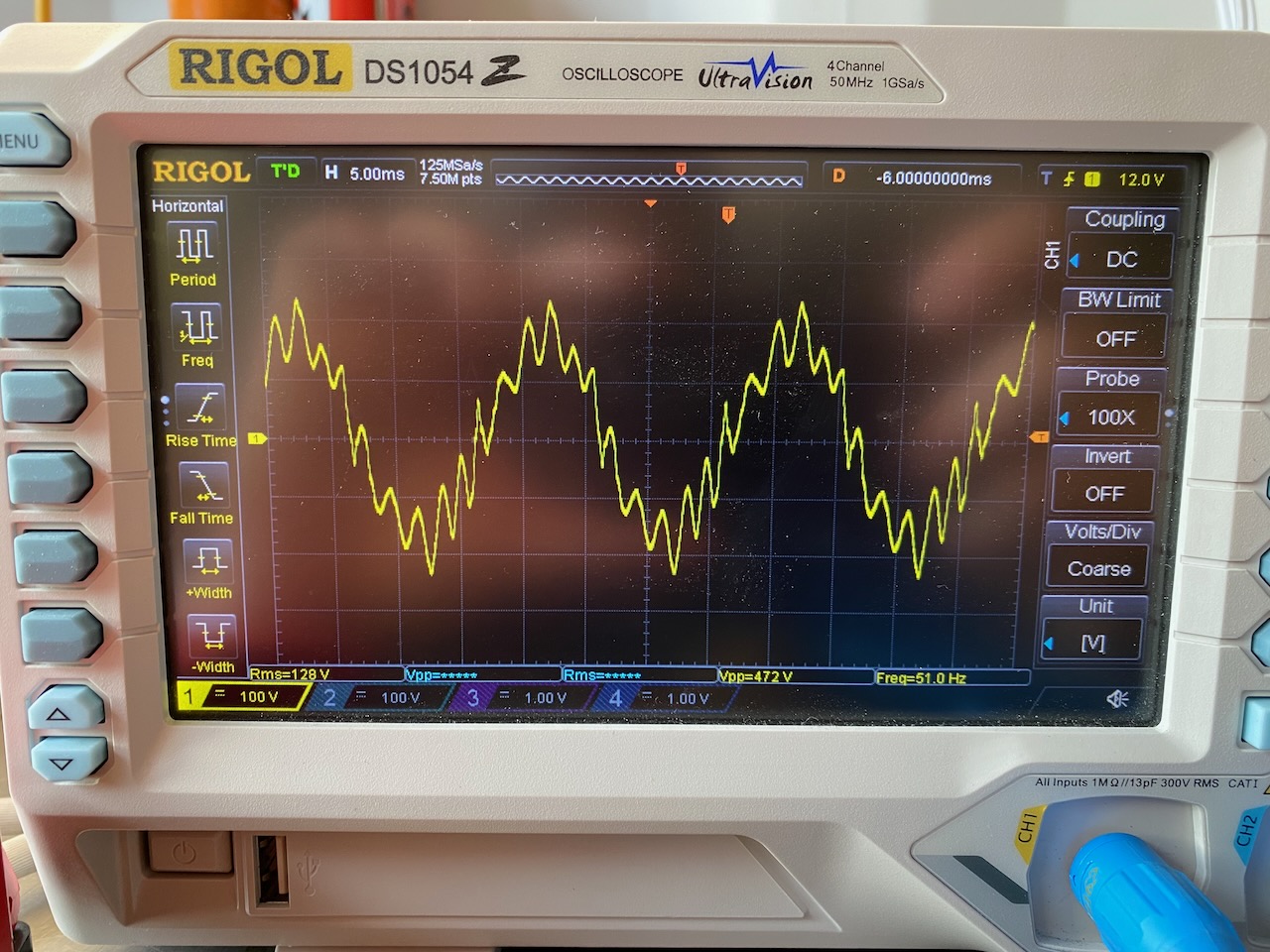
Unloaded
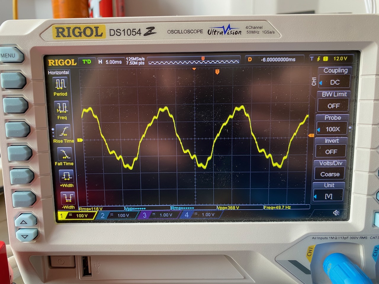
These scope shots only show one-half of the generator output voltage, as I didn’t have an isolated scope probe handy, and the generator output is centre tapped to earth. So the total peak voltage is 472V unloaded and 368V under full load. These would equate to 335V and 261V RMS with an ideal sine wave. Since the actual RMS is 256V unloaded and 232V loaded, we certainly have some evidence of waveform distortion under both conditions.
Fully loaded
So on the face of it I could see how this could trip the welder’s overvoltage protection. I also heard from a friend who had experience of using similar generators to power his ham radio field day stations, and he said the waveforms tended to be “thin” with too high peak voltage for their RMS.
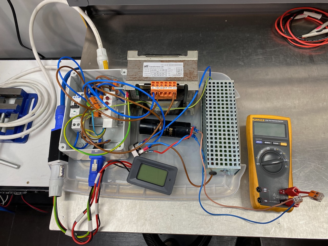
I pondered various ways of attacking the problem, a filter to remove the tooth ripple? This would need some seriously expensive and bulky inductors, so I didn’t bother. My first experiment was to step the output voltage down using an autotransformer (as I had one handy) and clip the peaks off using a rectifier, capacitor and resistive load.
This contraption (which I’ll call the Happy Welder 3000) worked surprisingly well, using the 190V tap, the peak and RMS voltages were both brought somewhat under control, and I was able to crank the welder to about 150A output at which point the engine began to bog down and belch black smoke, but would recover by letting off the TIG foot pedal.
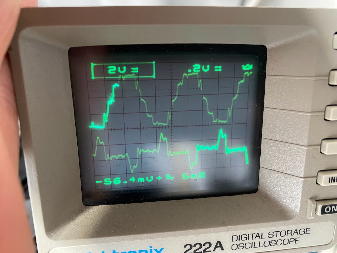
Voltage and current drawn by the peak clipper
The Happy Welder 3000 seemed like a bodge so I went looking for a more elegant solution. I discovered that just switching the generator to 115V would give a decent result with no extra hardware needed. Voltage drop in the 25m x 2.5 sq mm extension cord (used to get generator noise and diesel fumes away from me) now limited me to a somewhat lower welding current before I got error “US2”, undervoltage this time. I was able to do a small job on mild steel this way.
I spent way too long thinking about this problem and ended up building an AVR which to my surprise, made the problem even worse! The welder was quite happy with 200V from the autotransformer, but with generator output reduced to 200V by the AVR, it wouldn’t run for more than a fraction of a second before tripping on error US1.
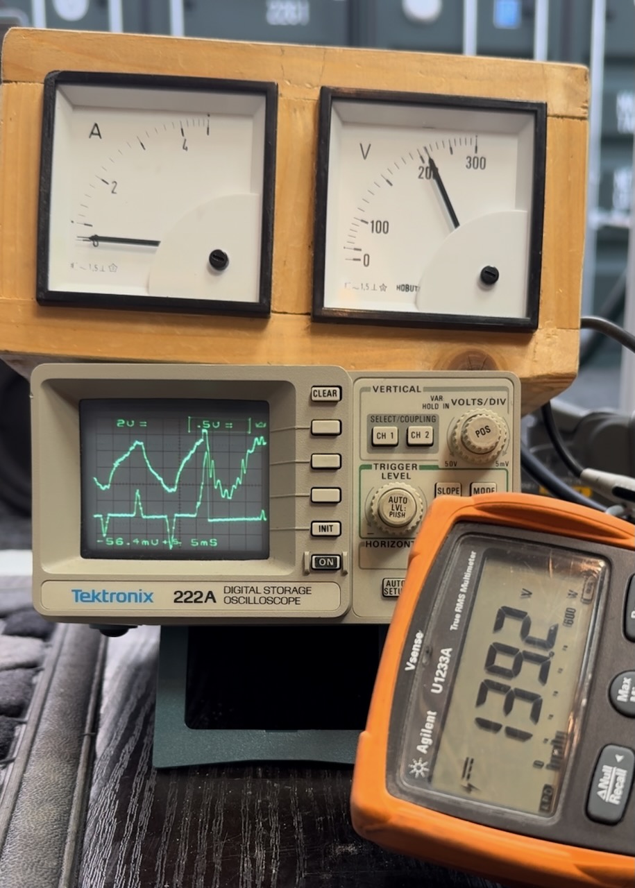
I don’t know how it took me so long, but I eventually stumbled on the idea of filming the scope screen while welding and examining the footage frame by frame.
I believe this frame captures the instant that the welder shuts down on error US1. Top trace is generator output voltage, bottom is current drawn by the AVR’s peak clipping channel. DVM shows the voltage across the AVR’s filter capacitor, which should be one-half of the peak output voltage.
The waveform is completely different to any I saw previously, and leaves only one possible explanation, the impedance (resistance and inductance) of the generator windings is too high for the welder’s PFC front end, it goes unstable and wrenches the waveform out of shape.
The instability pushes the peak voltage way higher than anything I measured while not welding, and does this so quickly that the meters I’d been using didn’t have time to register it. The AVR’s peak clipper tries to keep the peak voltage under control but fails.
This explains why stepping the voltage down to 200, and switching the generator to 115V, both worked and enabled me to weld, but using the AVR to reduce the voltage to 200 didn’t.
Switching to 115V gives an impedance one-quarter of the 230V setting. A transformer that steps the voltage down from 240 to 200 reduces the impedance to 76%.
On the other hand, the AVR only compensates for relatively slow fluctuations in voltage by adjusting the field current. It has no effect on the resistance and inductance of the windings, so can’t do anything about the waveform distortion.
I think I earned my professional development points on this one.
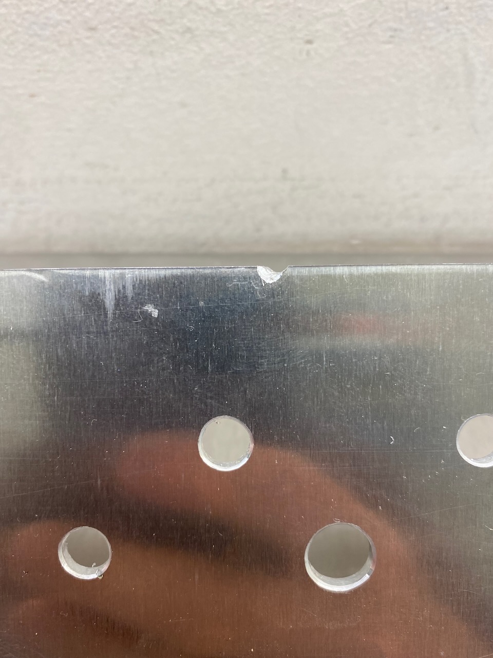
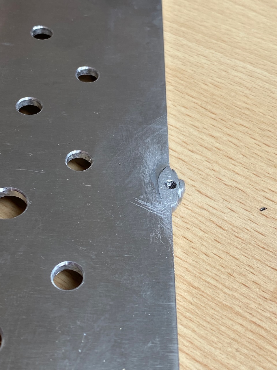
I started with a 3mm piece of aluminium pre-cut to size by Metal Supermarkets. The existing screw holes were easily replicated with PEM nuts, but the old faceplate vibrated horribly, so I wanted to add 2 more mounting bolts, and oh dear, the drilling for the top one just missed the panel.
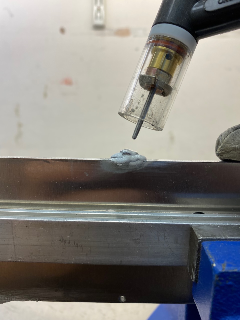
This was a perfect excuse to zap something with the TIG welder.
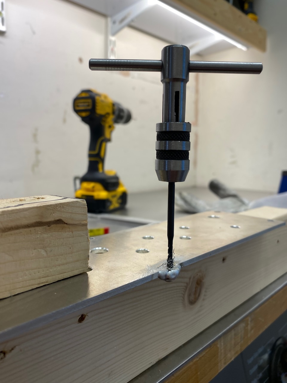
Zap and tap
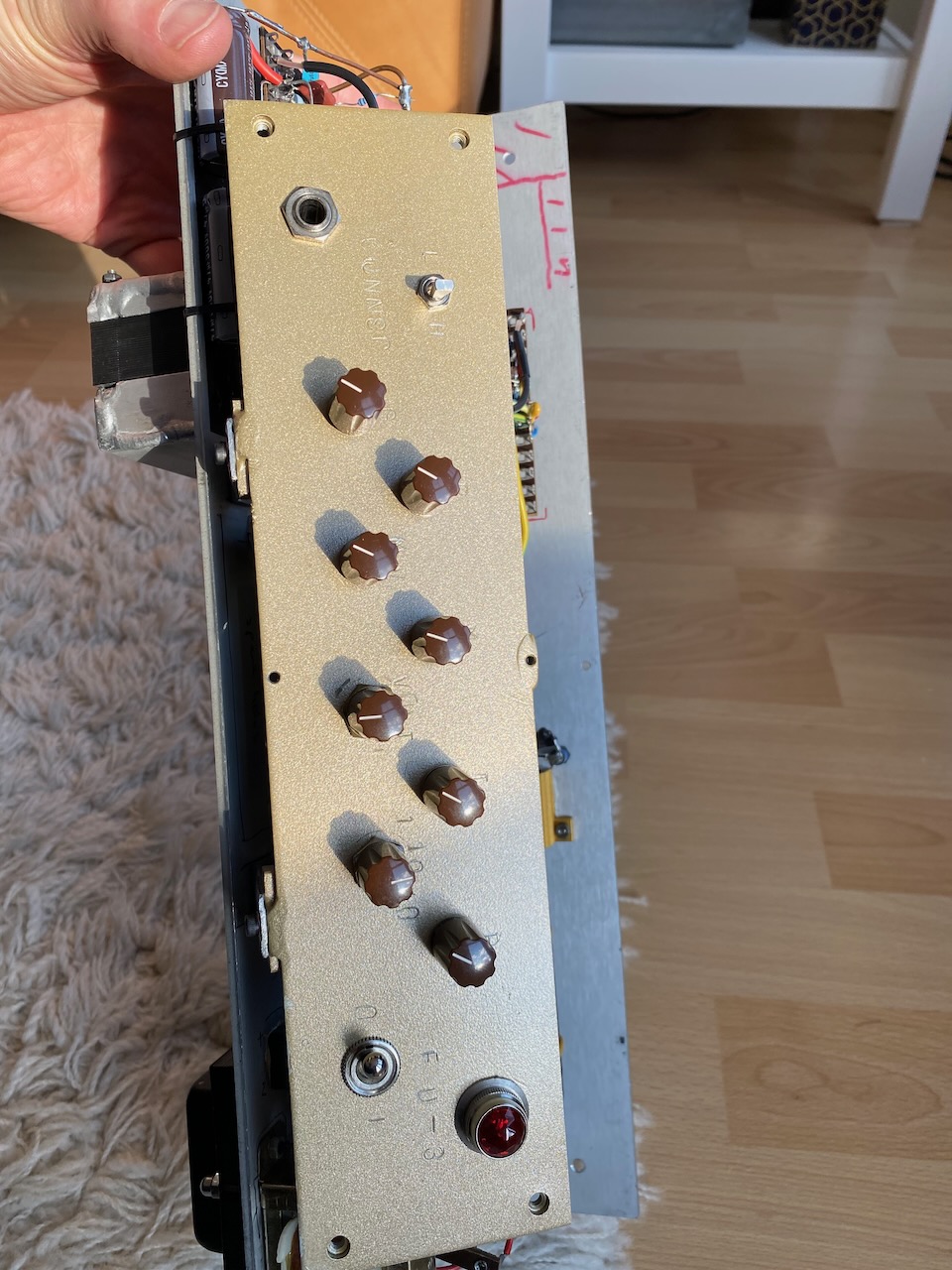
With this done, a coat of gold paint and a pasting with letter punches…
Wanted a track light fitting for the living room and more aluminium welding practice 🙂
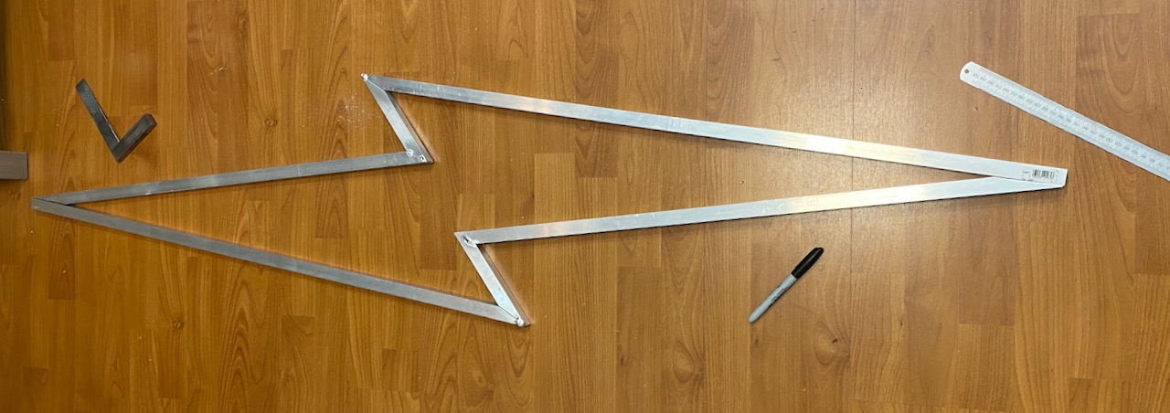
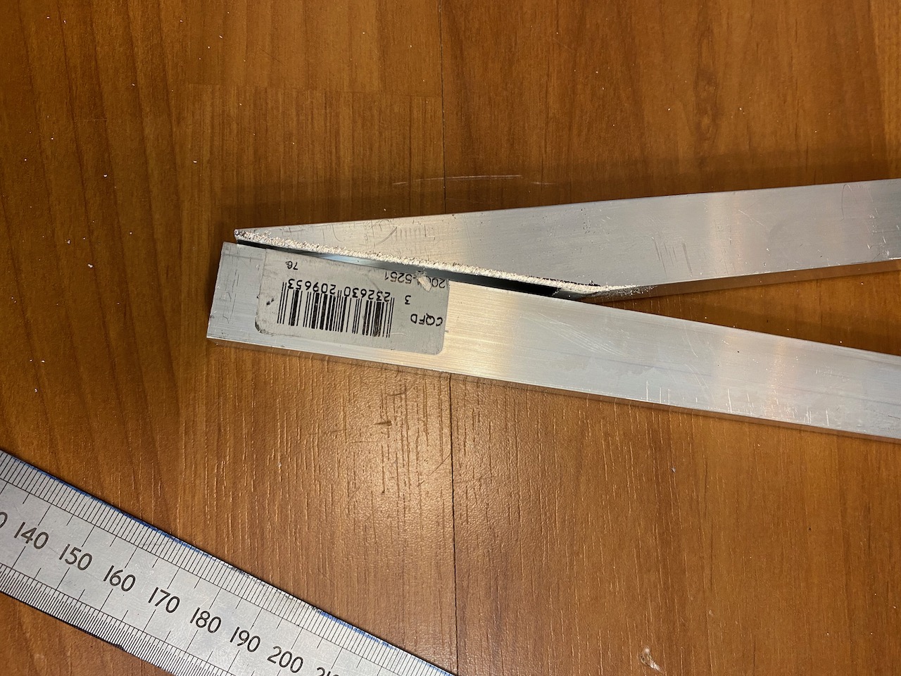
20x20mm square tube (ashamed to admit I bought it from B&Q) was cut into the shape of a lightning bolt.
Oh dear, the mitreing could have been better…
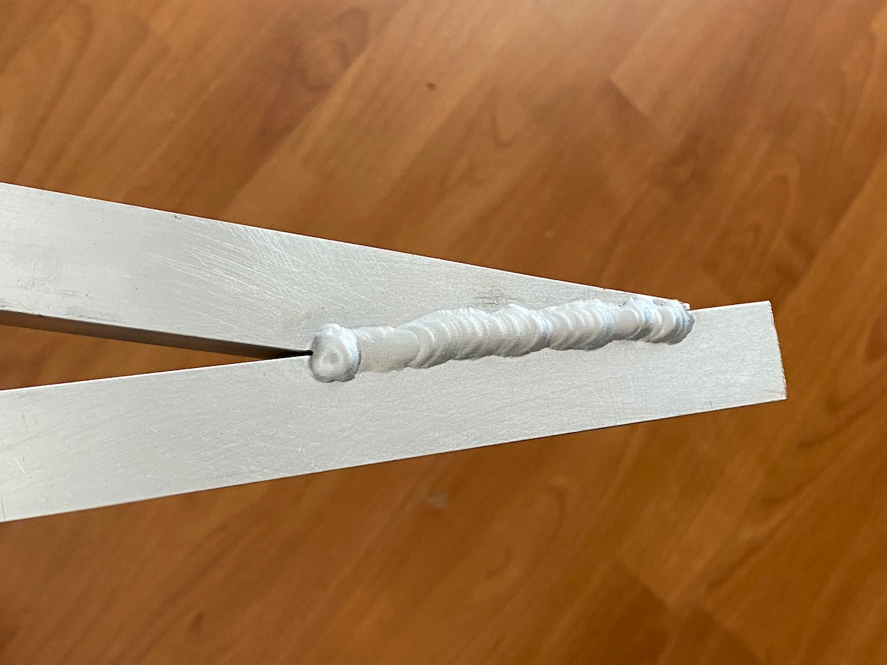
This is the nicest weld, there were much worse 😀 I got off to a bad start by burning several holes in it while trying to tack it together, and had to weld up the holes. I didn’t realise the tubing was only 1.6mm thick and started off with too large a tungsten and too much current. Another reminder to always test the welder settings on a scrap of the material you’re going to use… 🙂
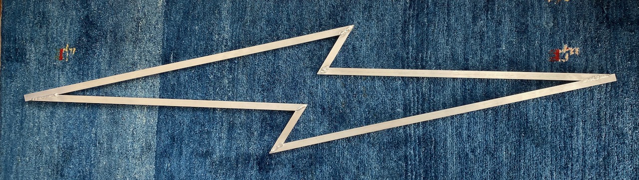
After fully welding (OK I didn’t do the inside corners 🙂 )
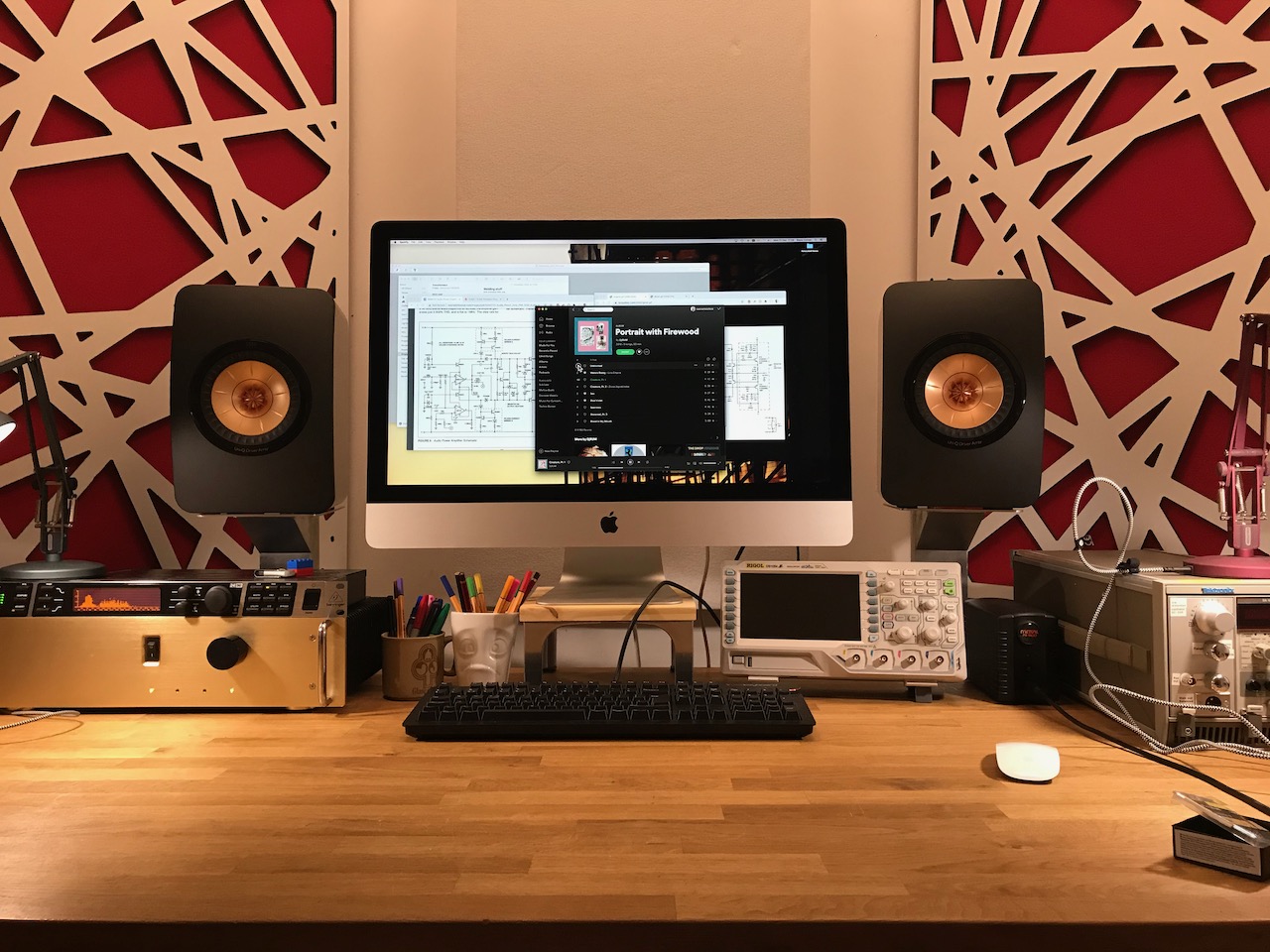
I was looking for an aluminium welding project that wouldn’t kill anyone if it failed. And also some speaker stands that wouldn’t take up any desk space.
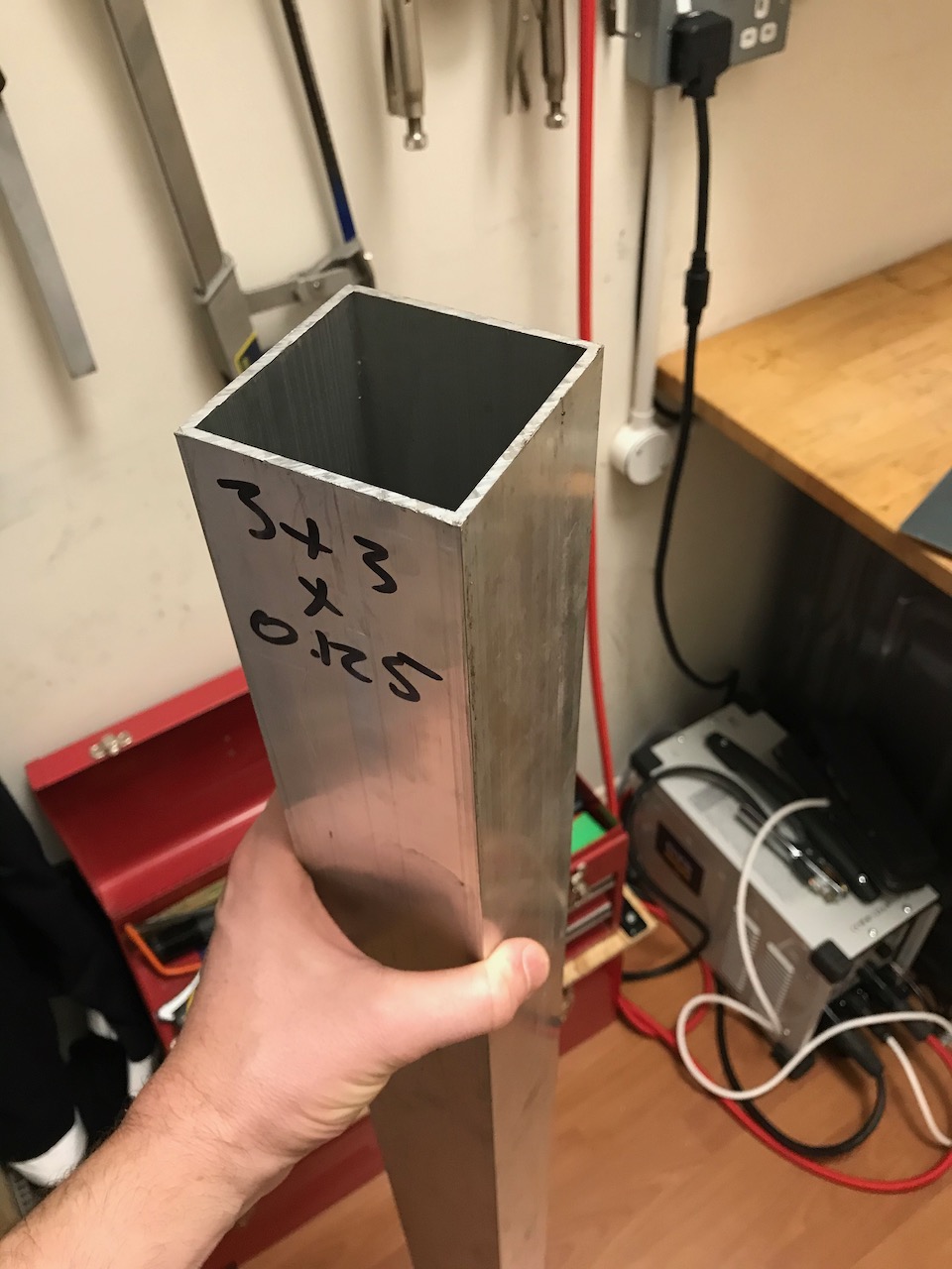
I started with a 1m length of 3″ x 3″ x 1/8″ box section.
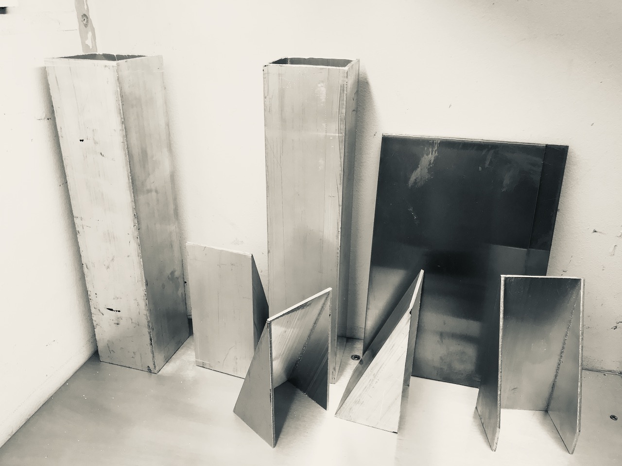
After a whole afternoon of hacksawing, jigsawing and filing it was reduced to 2 columns and some wedge shaped pieces.
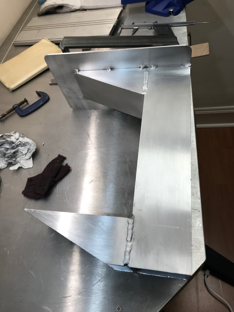
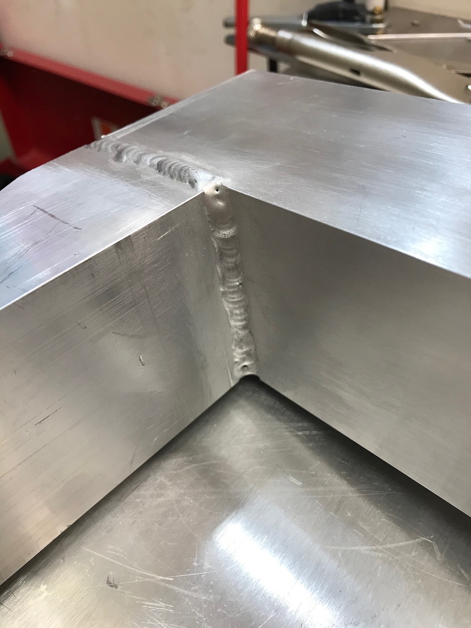
The pieces were then welded together into a giant C clamp shape and a 3mm plate was welded to the top to support the speaker. I decided to only tack weld the plate because I was worried the heat of a full weld would warp it.
I find the fillet weld the most difficult. This doesn’t exactly look great but it’s my best yet.
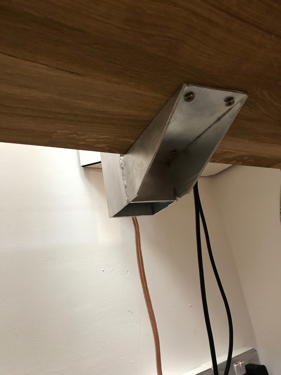
The stand base screws to the underside of the desk with some hefty wood screws.
The desk is completely clear and there is plenty of room underneath for oscilloscopes, soldering irons and so on.
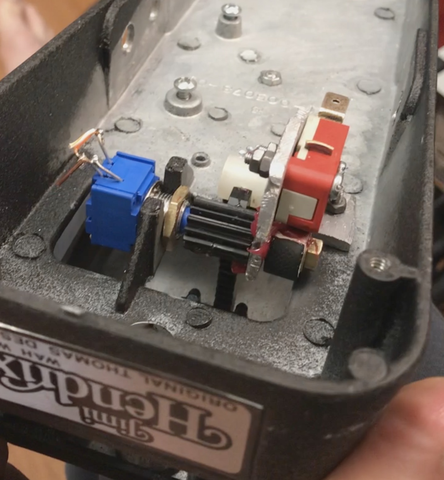
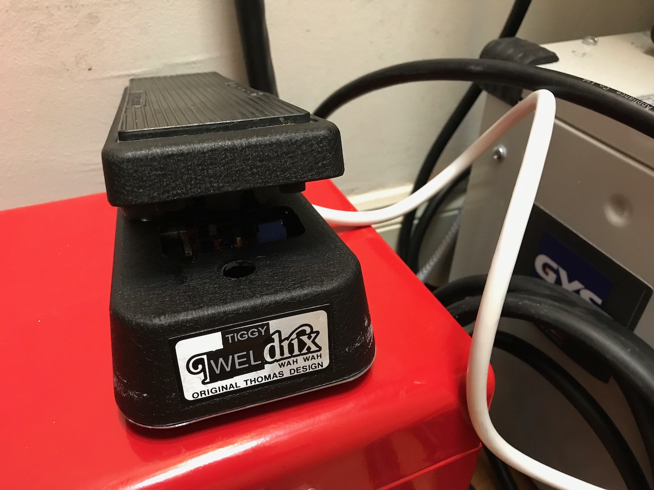
I got fed up with the thumb controls on the torch that came with my welder and decided to try a foot pedal. They are extremely expensive to buy so I decided to make one out of an unwanted wah pedal.
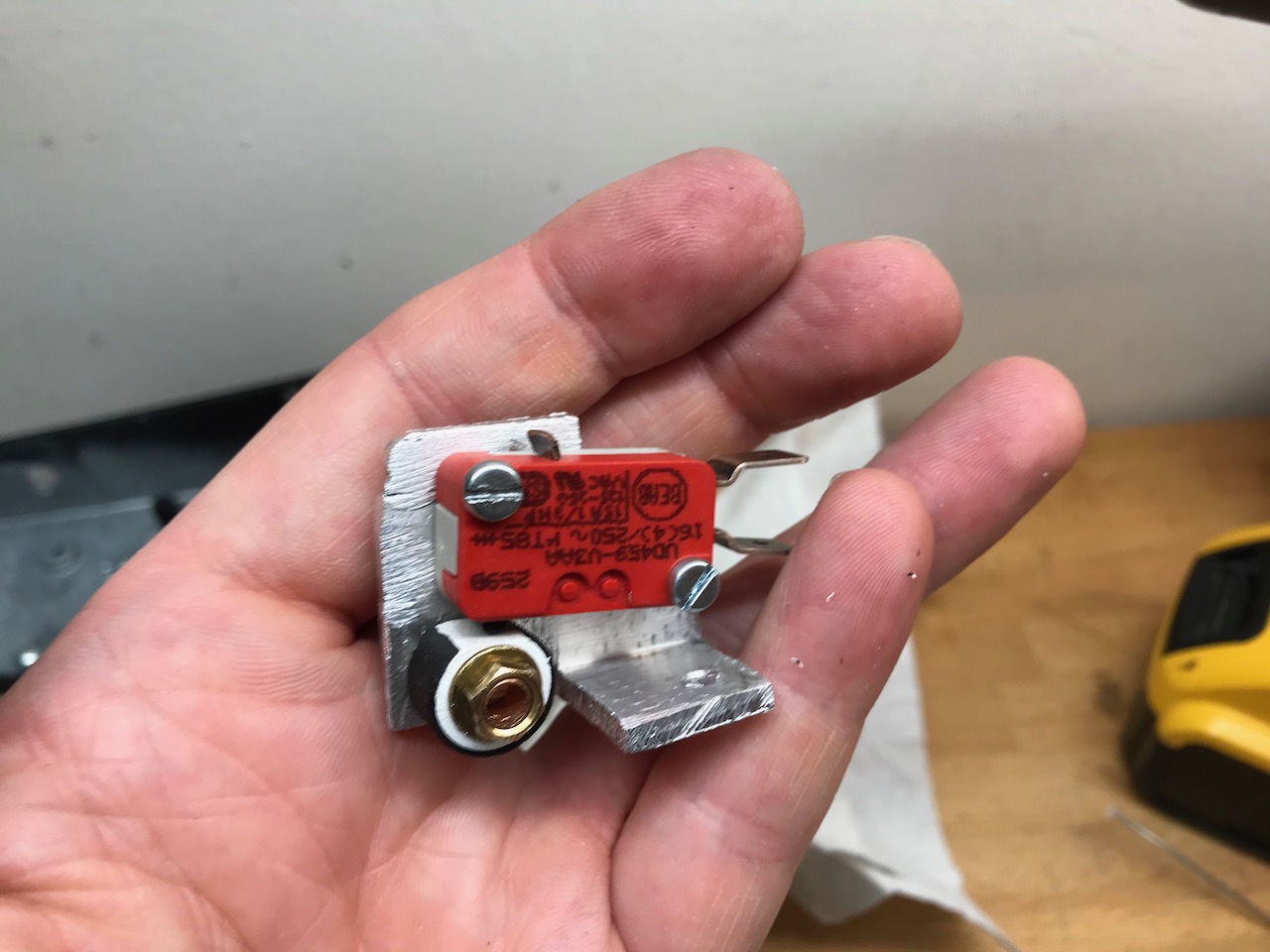
First, a bracket 🙂
The main difference between a wah pedal and a TIG foot pedal is that the switch engages as you first apply pressure to the pedal, telling the welder to open the gas valve and go through its preflow and ignition cycle. Depressing the pedal further then controls the welding current.
To allow this operating mode I threw away the existing stomp switch and replaced it with a microswitch operated by a cam.
The other difference is that it needs a rather strong return spring to avoid igniting the welder by accident. I found this out by trial and error. D: Keeping with the musical instrument theme, I used some Strat tremolo springs from eBay.
I connected it to the socket for the hand controller as a spare plug for this was supplied with the welder. It thinks it is a torch with 1 button and thumbwheel. This seems to work fine, but I will try the foot pedal socket if I ever get round to figuring out the mating plug for it.