All this power is nothing without control.
Luckily by using silicon carbide power devices, we were able to handle all the power we needed with a simple boost converter switching at 100kHz. No need for multi-phase or fancy energy recovery snubbers- it’s just a domestic appliance-sized PFC front end scaled up.
This means we can also use a controller intended for said domestic appliance PFC. I used the UCC28180 PFC controller chip from TI, because it only has 8 pins and is marketed as “easy to use”, therefore it can’t possibly go wrong! 😀
(OK, I bought the evaluation board and tested it with some Tesla coil-like loads before committing)
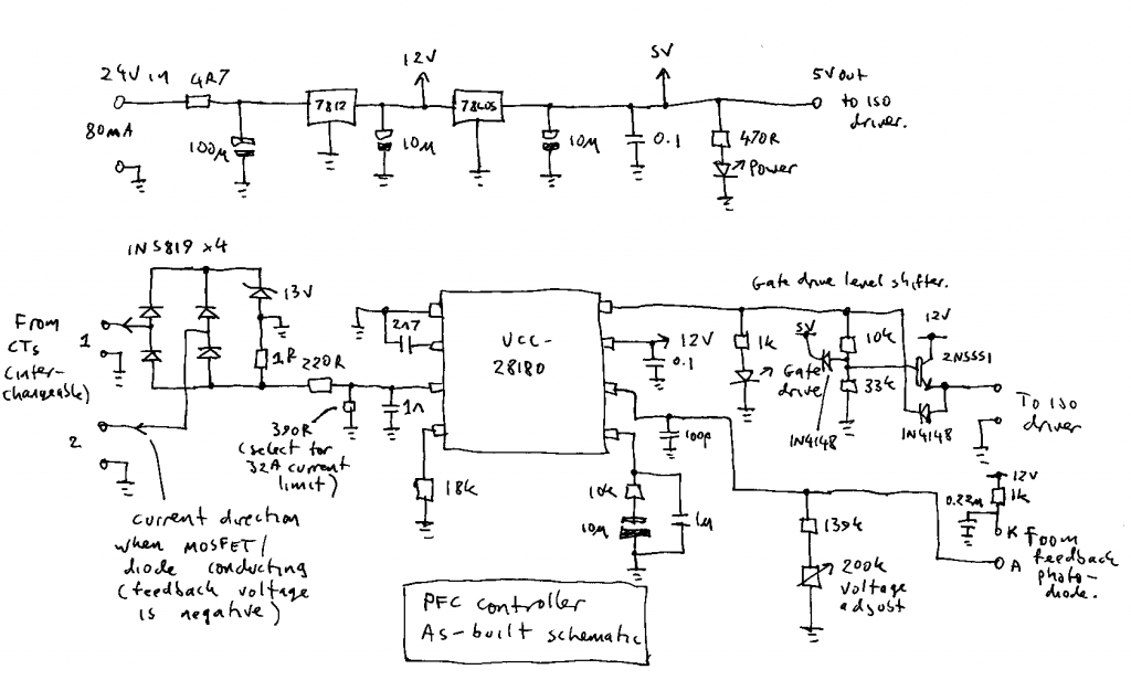
This is the circuit I ended up using. It’s quite different to the original TI application circuit, so I’ll describe the differences.
Compensation: TI provide 2 full pages of formulae for calculating the compensation components, and ain’t nobody got time for that! So I took the values from the evaluation circuit, and doubled the capacitors and halved the resistor because it seemed like a good idea.
Gate drive: Silicon carbide MOSFETs need a negative gate voltage to turn off, and the UCC28180 doesn’t provide this, so I had to make a separate gate driver, which I’ll describe in the next post. The Silabs isolated gate driver chip needed a 5V supply and a 5V signal, so I had to add a level shifter and a 5V regulator.
Inductor current feedback: The UCC28180 is designed to take feedback from a resistor in the DC bus negative. This is a very common design choice in small PFCs. I added the 4x 1N5819 diodes and associated circuitry to adapt the signal from the CTs to look like it came from the original resistor. The 13V zener is used to clamp the spikes when the CT cores reset. A value of 13V guarantees reset even with the maximum duty cycle allowed by the controller chip.
I tested the CT feedback on the UCC28180 eval board before committing to building the full sized version, in case the chip turned out to be unhappy with it for some unforeseen reason, but it performed identically to the original resistor feedback, as far as I could tell.
Voltage feedback: Since the CTs provide isolation of the current signal, and I ended up using an isolated gate driver, I decided to isolate the voltage feedback too so the control circuit would be completely isolated from the high voltage side. I used a simple circuit based on the HCNR201 linear optocoupler and a TL071 opamp.
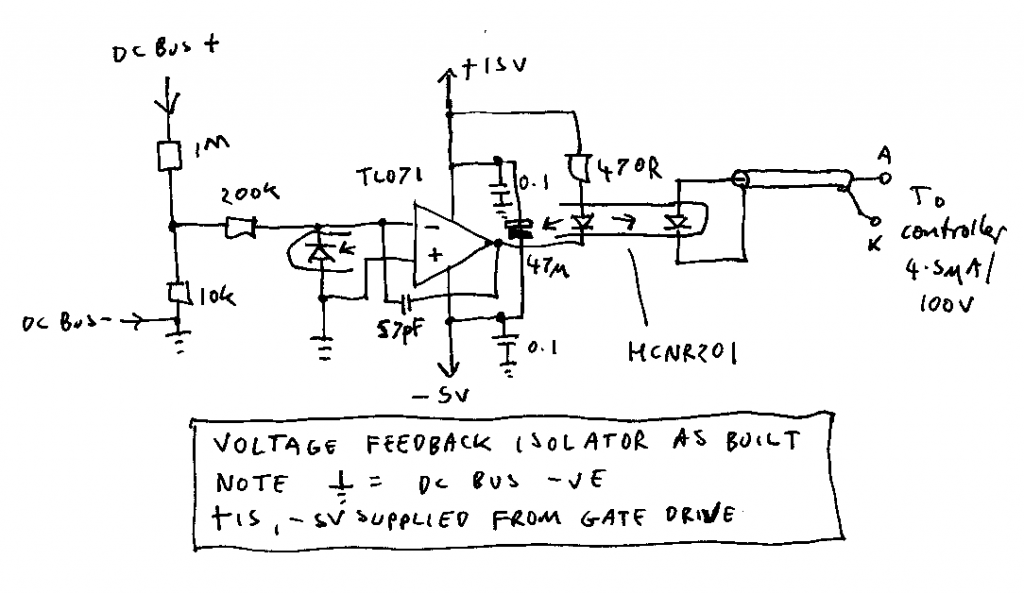
The voltage feedback input of the UCC28180 has a high enough impedance that it can accept the current from the photodiode (4.5uA per 100V DC bus voltage) directly with no amplification or buffering. This simplifies the circuit considerably and provides some nice synergy. The UCC28180 has circuitry to detect an open feedback network, a dangerous condition that can cause the output voltage to run away, blowing up expensive pieces of power electronics. By configuring the voltage feedback in this way, the protection still works for an open circuit anywhere in the signal path, including forgetting to plug the isolator into the main board, and loss of power to the isolator’s opamp.
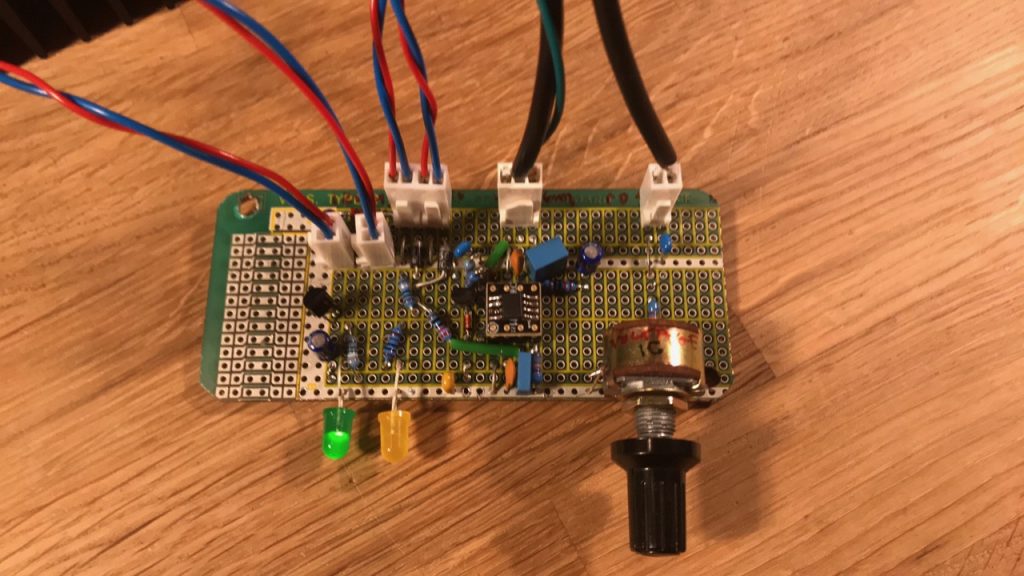
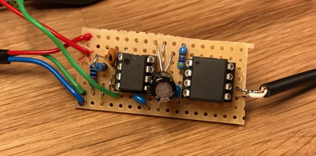
Both circuits were easily constructed on protoboard with through hole components (and an adaptor for the UCC28180)
Leave a Reply