Before I could get on with building the PFC into an enclosure, I had one last design decision to make: What sort of EMI filtering to use. The size and shape of the EMI filters would affect the rest of the mechanical design. Ok, that’s management speak for “How am I going to get all this cr@p into the 3U rack enclosure I’ve already purchased?”
Now, I deal with EMC in my day job and am vaguely familiar with the standards and test procedures, but this is a one-off handmade power supply for a Tesla coil. It’s never going to get tested for emissions, and the emissions from the Tesla coil will dwarf the contribution from the power supply anyway.
So the main purpose of the EMI filters is to protect the PFC from malfunction or damage caused by the Tesla coil emissions. These tend to be common mode transients caused by ground strikes, containing frequencies up to the 10s of MHz. There isn’t a great deal of VHF or UHF energy due to the length of the spark channel. So they really aren’t super hard to filter out.
I prefer to connect the filters so the Y capacitors (jargon term for the capacitance between lines and ground) are at the end connected to the outside world. My reasoning is that I’d rather any incoming transients were dumped to chassis ground through the capacitors, than potentially flashing over a choke.
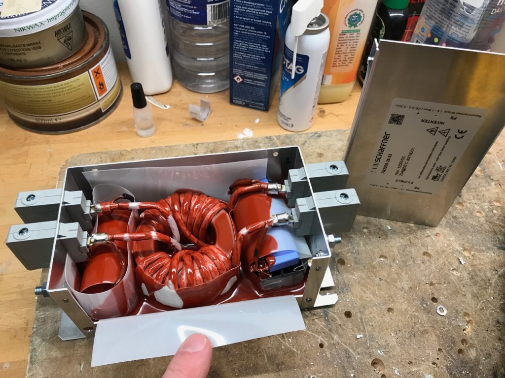
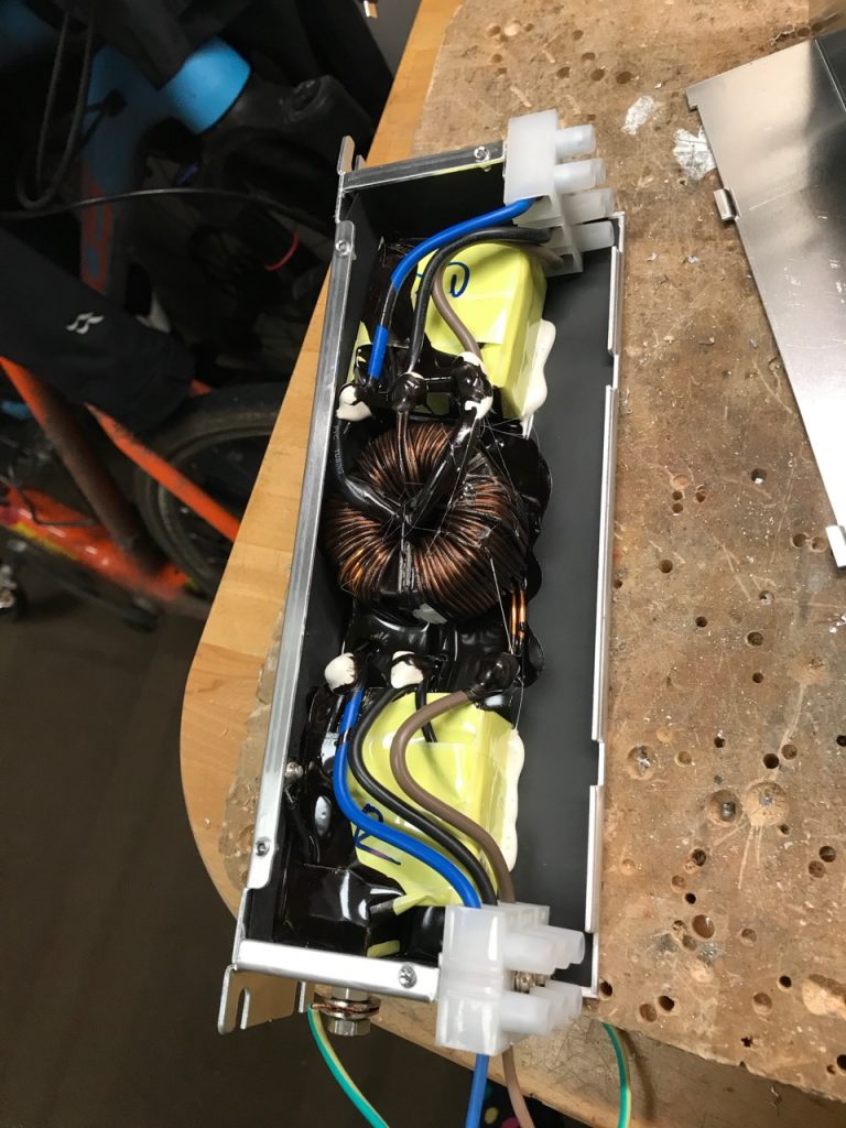
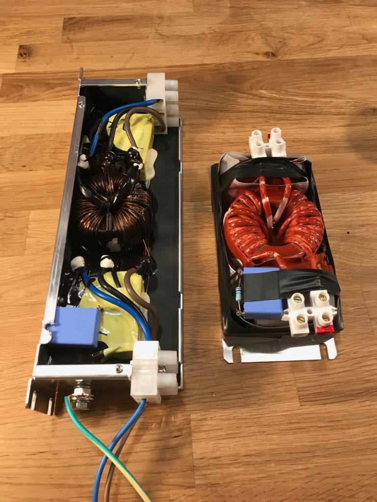
I started by trawling the RS, Farnell and Mouser catalogues for ready-made EMI filters. I ended up with a Delta 30TDVST2 for the input and a Schaffner FN2200-25-33 for the output. These both had the Y capacitors at the load end, so would have to be used backwards from the maker’s recommendation.
I soon discovered a serious problem with both filters: a very high Y capacitance. This isn’t a problem in the intended industrial application, but a bit of a show-stopper for mine. When the PFC is used on a single phase supply, the high capacitance causes enough earth leakage current to trip any RCD. Note that the Y capacitance of the DC output filter also contributes to the leakage, because the DC output is not isolated from the mains and has AC superimposed on it.
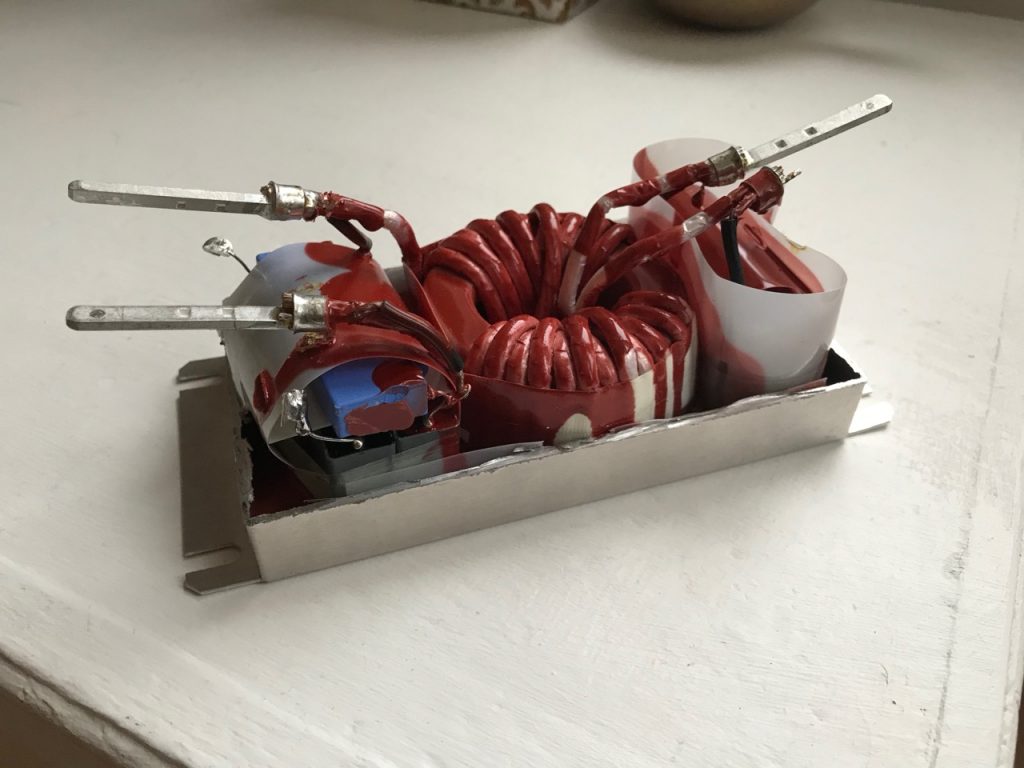
I couldn’t find any better filters, so I broke them open and set about reducing the Y capacitance.


I lifted the connection between Y capacitors and earth, and added a 68nF capacitor in series, with a 2.2M discharge resistor. This should give a total leakage current budget of around 10mA at 240V AC. (Odin has 2 68nF capacitors from DC bus to ground already, which contribute too)
The modified filters no longer tripped my house RCDs, so the job was done. In hindsight, I wouldn’t buy ready-made filters again. It would have been cheaper to buy the parts and make them.
Leave a Reply