I spent entirely too long pondering why Lister wouldn’t run the welder, and decided to build an automatic voltage regulator (AVR) for the generator to investigate further. My reasoning went as follows: If stepping the generator output voltage down to 200V from 240 made the welder happy, then surely regulating it down to 200V would do the same?
I started out intending to build a straight copy of the Homo Ludens AVR2 but it mutated and mutated eventually turning into the above circuit.
The AVR2 is simple and ingenious, but:
I wanted an accurately defined 200-240 or 100-120V adjustment range.
I discovered the principle of keeping the peak voltage under control with a bridge rectifier and large capacitor, and wanted to include that and make it track the average voltage, without using a multi-gang pot.
The Homo Ludens circuit needs a normally closed relay to start up. I accepted his challenge of getting rid of the relay.
The Homo Ludens triac output stage really didn’t work that well in practice with my generator that derives its field excitation from its main output. It mostly functioned as an on-off switch and hardly gave any range of phase angle control.
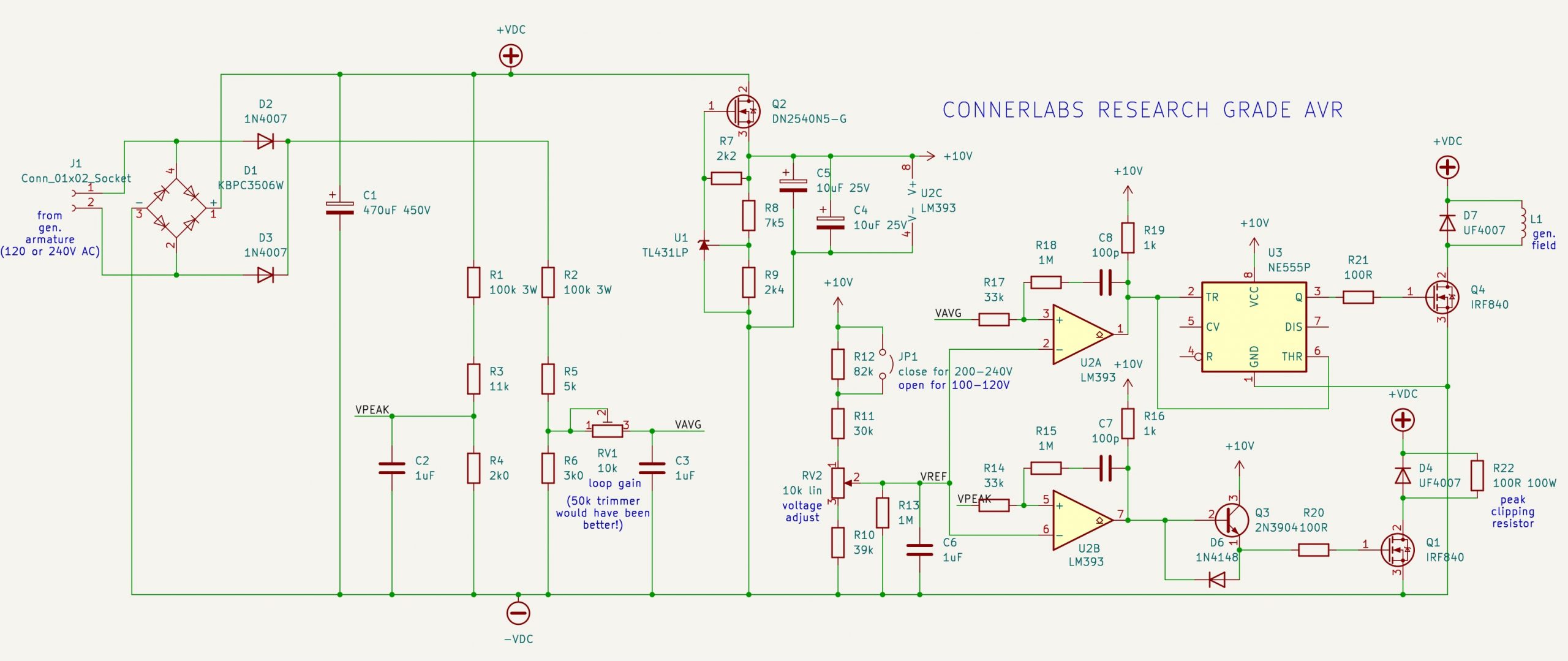
Explanation of my circuit:
The whole circuit is powered off the rectified and filtered output voltage of the generator. This can be either 115 or 230V nominal. C1 charges to something between 140 and 360V DC in use, clipping the generator peak voltage as it powers everything.
Depletion MOSFET Q2 and regulator U1 work together to provide an accurately regulated 10V supply that powers the low voltage part of the circuit and also functions as the voltage reference. Using a depletion MOSFET here allows the circuit to start with less than 10V AC from the generator, achieving the goal of getting rid of the Homo Ludens relay. The DN2540 is also a really docile part with quite low gain, and showed no signs of oscillation. It does get rather warm and would need a small heatsink when the circuit is running in 230V mode.
R1-R6 form two voltage dividers that sense the peak and rectified average generator output voltage. C2 and C3 provide some low-pass filtering of ripple, and for the average channel the amount of filtering is adjustable by RV1. The operating concept of the circuit is basically the same as the Homo Ludens one: the field coils and clipping resistor are driven by PWM, and the ripple on the sensed voltage functions as the PWM carrier. The smaller the ripple amplitude, the higher the control loop gain. Again like the Homo Ludens AVR2, this is a proportional controller only, no attempt was made to add integral or derivative terms.
The voltages are all scaled such that 40V RMS true sine wave input gives 1V at VPEAK and VAVG. RV2 and its associated fixed resistors make a reference voltage that varies between 2.5 and 3.0V in 120V mode, or 5.0 to 6.0V in 240V mode, thus giving adjustment ranges of 100-120 and 200-240V.
U2A and U2B function as comparators with a little AC hysteresis to avoid multiple transitions and high frequency oscillations. The values were found by trial and error to give happy PWM at twice the AC frequency.
The output stages are quite conventional, though scraping the junk box somewhat at this point. A 555 was used as an inverting MOSFET driver, and Q3 as a non-inverting one. A TC4428 dual MOSFET driver chip would have been a more elegant solution. The IRF840 and UF4007 were chosen by the same junk box scraping principle.
The original Homo Ludens optoisolated triac output stage can of course still be used with this circuit. Connect the opto-triac LED between U2A output and +10V. I would be interested to try this with the common and low cost “brushless self-excited” generators, connecting the triac in series with the capacitor. Internet wisdom says that these can’t be AVRd.
This circuit was tested with 50Hz AC supply from a variac and found to have rather low gain even with RV1 at maximum. It took maybe 30-40V change in variac setting to go through the full range of PWM. A 50k trimmer for RV1 would have been better, and the peak clipping channel could do with a similar increase in filtering. (The two iron cored chokes and series light bulb are simulating a generator field winding.)
I decided I would try it with Lister anyway though.
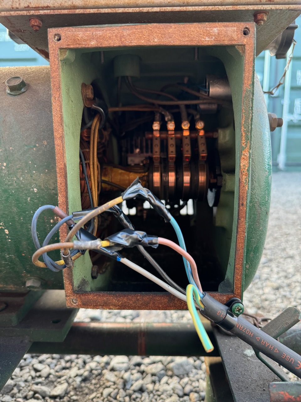
AVR was connected in place of original Brush generator excitation circuit. It used a variable series resistor and bridge rectifier connected to one of the generator’s 120V sections, so I did the same. With the generator switched to 240V I would only be sensing/regulating half of the output voltage, so I hoped the magnetic coupling between the two sections would be tight enough that the unregulated one would follow the regulated one.
The series fields with their excitation from rectified load current were left connected, while the AVR controlled the shunt field.
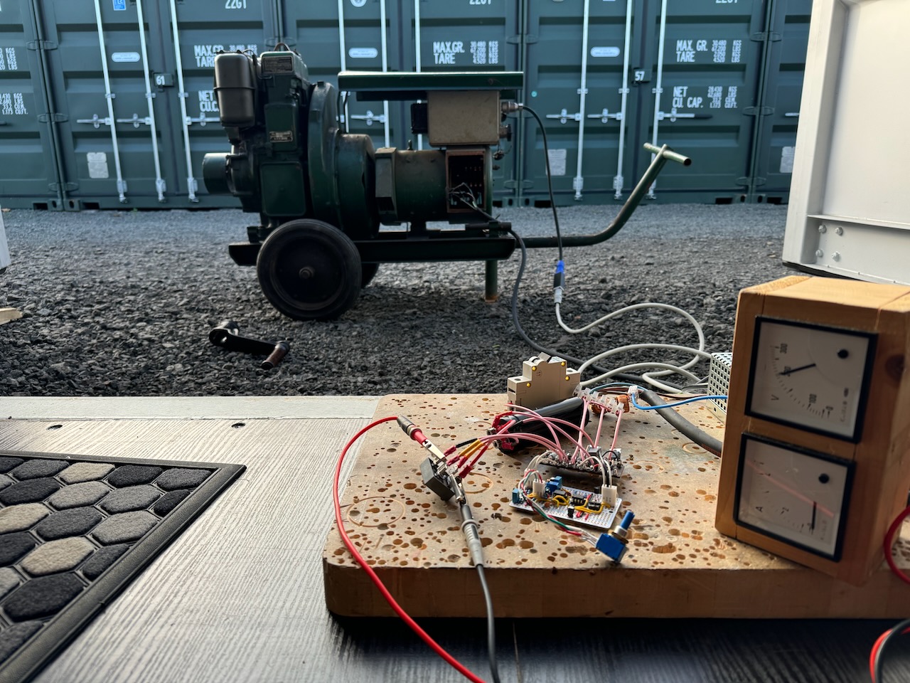
I take my breadboards seriously. 😀
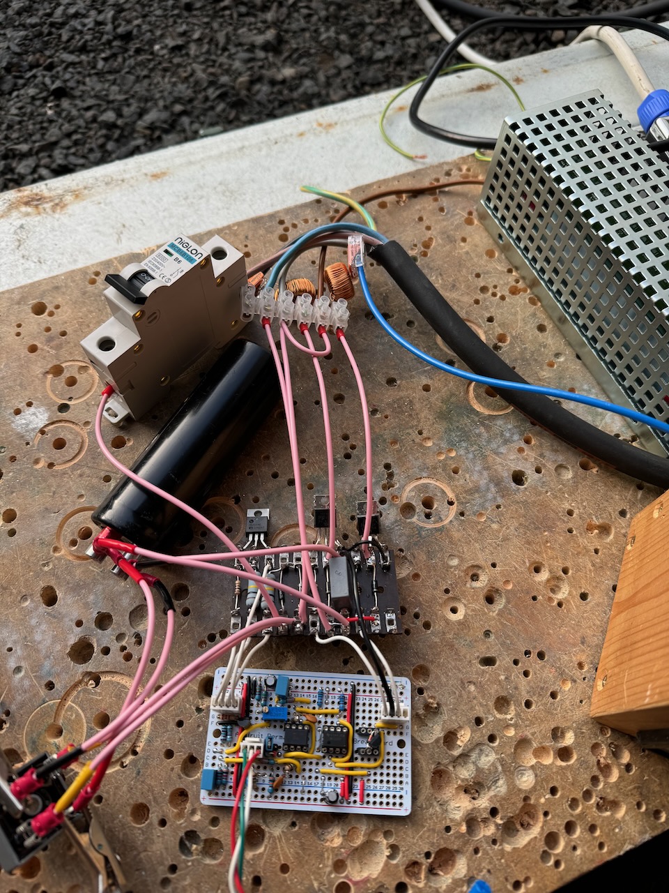
Note the small inductors (salvaged from dimmer switches) to filter out MOSFET switching spikes and reduce EMI.
Turning the pot adjusted voltage from 200 to 240V as designed. It worked a lot better than I expected from testing with the variac.
Throwing a 30uF capacitive load onto the generator to make it self-excite showed good control over the voltage.
Sadly it didn’t work, the welder would trip out almost instantly on an overvoltage error, even with the AVR turned down to 200V.
What I think is happening is that the average voltage regulating channel is quite slow to respond as it has to contend with the inductance of the generator’s shunt field coils, so for very rapid changes in voltage, it basically does nothing, the voltage regulation is determined by the impedance of the generator’s windings. Which turned out to be high enough to make the welder’s PFC front end unstable.
The welder PFC then ended up in a fight with the AVR’s peak clipping channel, one trying to distort the voltage waveform into a thin and peaky shape, the other trying to chop the peaks off. The welder apparently won, distorting the voltage to the point that it tripped its own overvoltage protection.
Leave a Reply