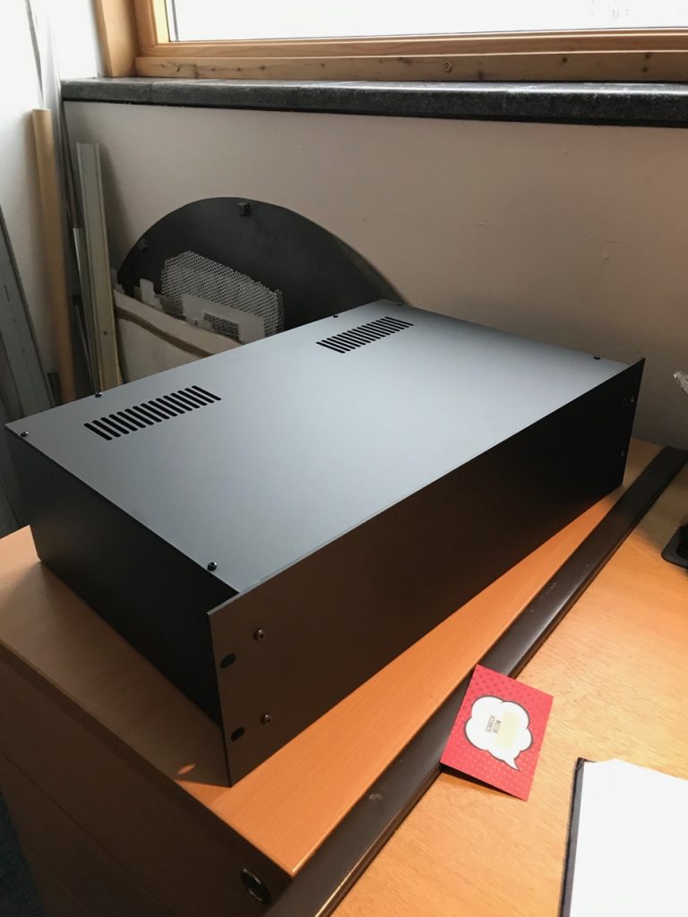
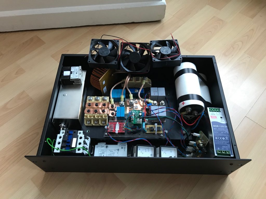
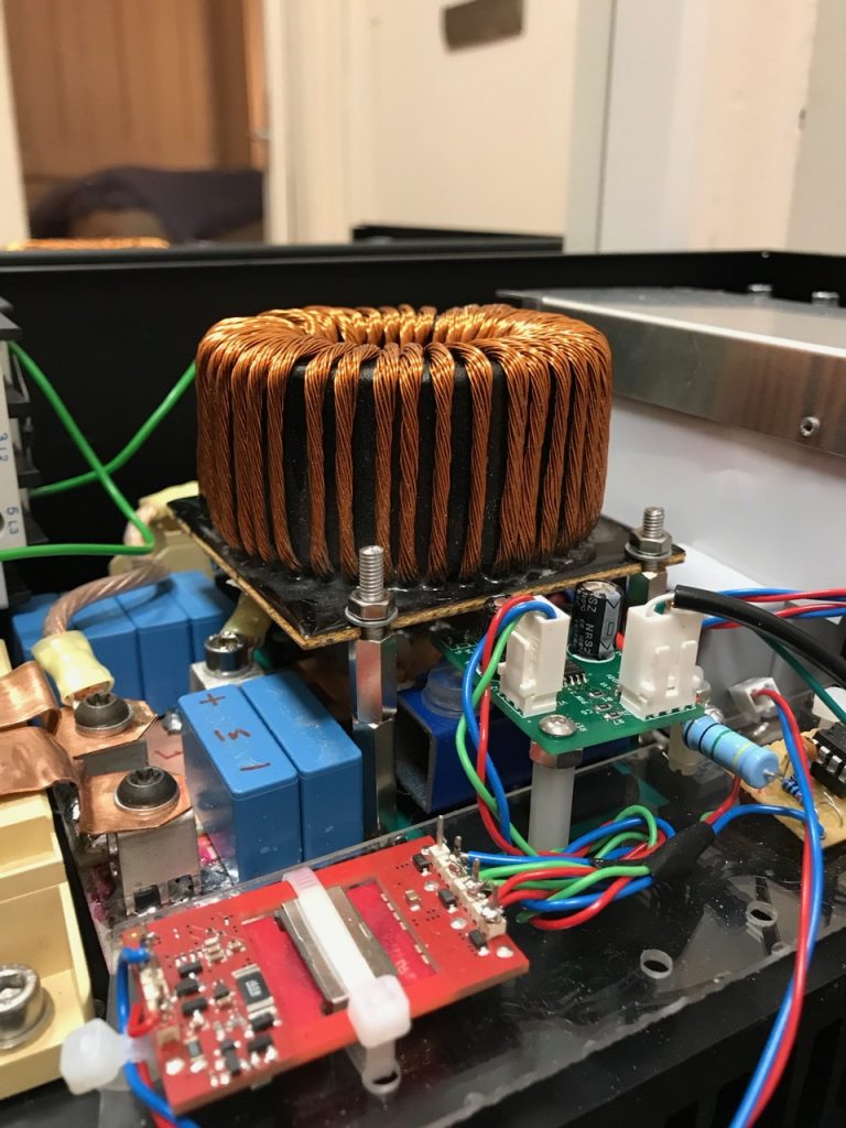
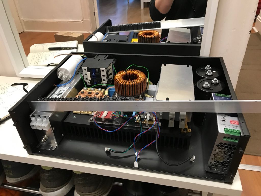
One of the joys of living in an old house is dodgy wiring. Another joy is ornate lath and plaster ceilings that might collapse at any minute. π My problem is a combination of the two. The overhead lights in most rooms are powered by 1930s vintage rubber and cloth covered wiring that can’t be replaced without trashing the ceilings.
As a token gesture to electrical safety, I added a RCD to the lighting circuit, and believe it or not it started tripping at random. This left me with a few options:
Stop using the ceiling lights altogether
Have them rewired and the ceilings replastered
Run the lighting circuit off a lower voltage that wouldn’t tax the ancient rubber and cloth insulation.
A lower voltage would of course limit the power that could be delivered before overloading the wiring. So the second part of the plan would be to replace the light fittings for LEDs to achieve a reasonable light output with less power.
I decided to go for 12V (in hindsight 24 would have been better- I ended up replacing the power supply with a 15V one as a compromise…)
First step was to source a reputable brand of power supply festooned with safety approvals. It will be left on 24/7 unattended, and it would be ironic to go to these lengths to avoid the wiring catching fire, only for the PSU to catch fire. π
I bought a few 600x600mm LED panel lights from TLC Electrical, and chucked the 240V drivers that came with them for some 12V drivers from Ebay.
They are still plenty bright enough.
The power supply was mounted next to the consumer unit and connected to the existing 240V lighting circuit with a FCU.
Oh dear… At this point I realised the thickness of the old wires was mostly insulation and the actual copper cross section was puny. To the point where a 11 amp power supply could potentially overheat them if one of the light fittings shorted out, leaving us no better off in terms of safety than before.
I connected it up anyway π
The first of the new light fittings in place
The other light fittings were modified with bodges like this
Later I added some fuses to address the issue of the PSU being able to overheat the wiring.
Ever since the Raspberry Pi came out, I’ve been experimenting with its audio capabilities. The latest audio gizmo available for it is the Wolfson Pi Audio Card, which promises 24 bit, 192kHz recording and playback, with analog and digital I/O, for a very reasonable price. So of course I ordered one straight away. π
After waiting a month I finally got my hands on it. The software installation is somewhat unclear so I will document what I did here. I didn’t want to use the Wolfson official image as it was a massive 8GB download. I started with a copy of the image that I developed for PiTunes, and applied this patch to it, which adds the Wolfson kernel and the support files for the audio card. I then changed mpd.conf to use audio output device hw0,0 (it was previously 1,0 for the USB audio device) and added a call to SPDIF_playback.sh in my .bash_login file, to set the card up for digital output.
I also removed the invocation of pikeyd from /etc/rc.local, as the keypad and encoder were not present. They can’t be used anyway, since the Wolfson audio card hogs all of the GPIO pins. It doesn’t really matter, as MPD can always be controlled remotely.
On firing this up, I was surprised to find that it worked first time! π I verified the output to be bit perfect at 24 bit, 96kHz. This is possibly the best value for money HD audio source you can get anywhere: you should be able to pick up a Raspberry Pi, a Wolfson Audio Card, a wifi dongle and a hard disk for under Β£100.
Dear reader, I apologise for the lack of blogging recently. Here is a double helping.
First of all, I’ve been having great fun with Reaper. Digital audio workstation software written by the charmingly named Cockos Inc. I remember trying an early version years ago and hating it, but it has come a long way. I’ve tried most of the DAWs, and I think Reaper is now my favourite, especially when you can buy a personal-use license for 60 bucks! (I bought it.) It is available for Mac and Windows, and the bundled collection of plugins isn’t half bad.
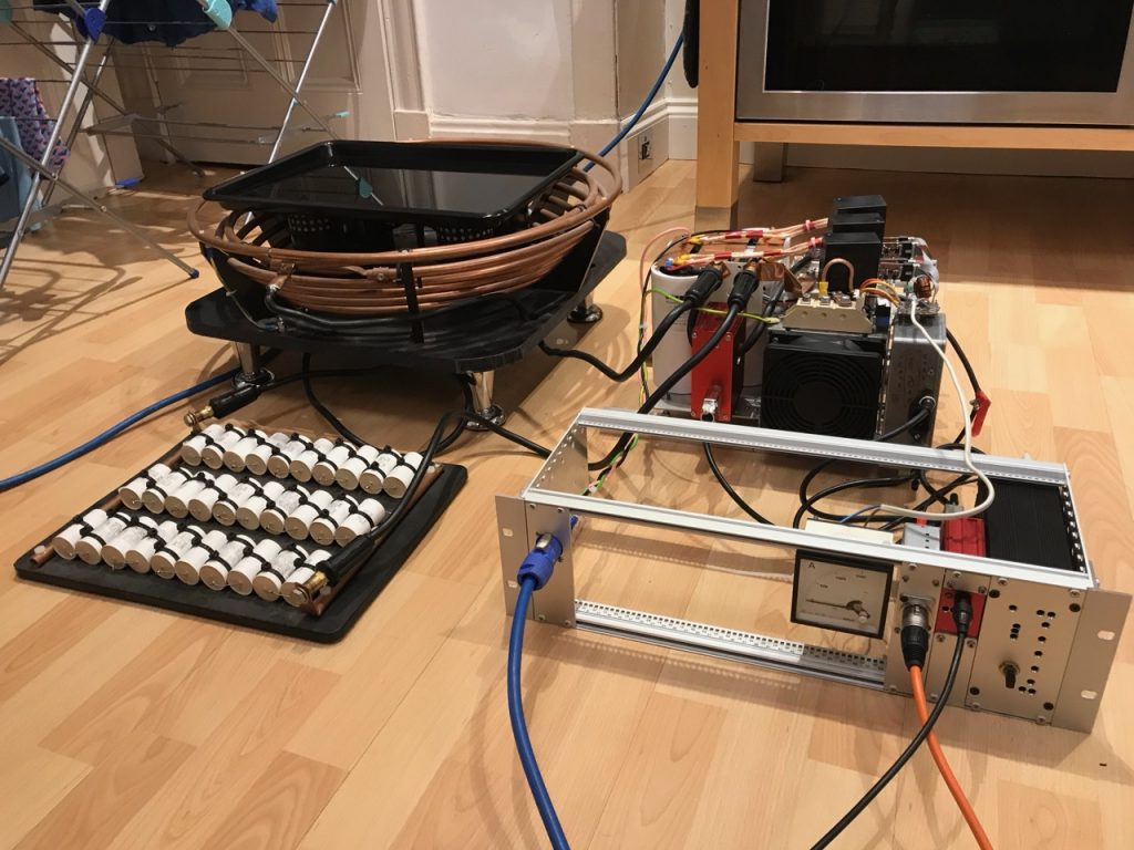
To all electronics experts reading, I apologise for placing the setup so near a radiator! π
So that’s reaping time, but what about the sheeping time? Well you know the old problem, when you need to edit the DNA of a cloned sheep but all you can find is an ancient gene splicing program that runs on classic Mac OS. Happens to us all.
I obtained a copy of the SheepShaver Mac emulator for Windows, and a ROM file and ready-to-use Mac OS 9 disk image from redundantrobot.com. I put it all on my old Windows laptop for a test. And, it werked!
This article (series of them with any luck) is inspired by Nick de Smith’s Quad 405 project. He was getting better distortion figures than my Blameless build: 0.002% at 20kHz! And from an amp that operated in Class-B and needed no bias adjustment or thermal compensation, how could this be? I had tried to understand the current dumping concept before, and failed, but this time I was determined!
So here is a simple, intuitive (and maybe even correct? π ) explanation of how current dumping works. Please refer to Snook’s DCD Mod-3 schematic, as well as the diagrams below, in which I’ve reduced the circuit to the bare minimum possible.
You can see that the amp consists of three parts. First, a Class-A, current feedback error amp. In the DCD Mod-3 circuit, the inverting input of this amp is TR2 emitter, the non-inverting input is TR2 base, and the output is TR7 collector.
Second, a hefty Class-B output stage that runs with no idle current. In the DCD Mod-3 this is TR8, TR9, TR10 and associated parts.
Third, what Nick de Smith referred to as the “Maxwell-Wien Bridge”. This is obvious in the DCD Mod-3 schematic. I’ve drawn it in the same way here, but I’ve labelled the components Z1, Z2, Z3, Z4 in accordance with Walker and Albinson’s original analysis.
Then, to make things a little clearer, I’ve drawn the circuit again, but replaced Z2 and Z4 with resistors, of values roughly equivalent to their reactances at 20kHz.
We’re now in a position to see intuitively how the circuit works. The error amp is looking at the output from the output stage, fed back to its inverting input through Z1,Β and comparing it to the desired audio signal on its non-inverting input. It amplifies the error by a factor of -(Z2/Z1) which is -100 in my circuit. This amplified error drives the output stage, like in any normal audio amplifier. But a portion of it is also fed forward directly to the speaker through Z3. This forms a potential divider with Z4, so the speaker sees the fed-forward signal attenuated by a factor of roughly Z3/Z4, which is 100.
So, the error got amplified by -100 and then attenuated by 100 again. It follows that the error gain to the speaker is just -1. In other words, an equal and opposite signal cancelling the original error, to give a perfect output. So, we’ve rederived the original Walker balance condition: Z2/Z1 = Z3/Z4, or Z1Z3 = Z2Z4 as Walker wrote it.
(I’ve taken some liberties with a “1” here and there: the potential divider really attenuates by a factor of 101. But so did Walker and Albinson and everyone else. I’ve also assumed that the output stage’s output impedance is negligible, and its input impedance is high enough not to load the error amp down and kill the feedforward signal. Again, I believe these assumptions were also made in the Quad 405 design.)
However, as every amplifier geek knows, Z2 is a capacitor and Z4 is an inductor. In fact, I remember Quad’s full page ads in the hi-fi press, that showed nothing but a picture of the inductor and the Queen’s Award logo.
Intuitively, what now happens is that the error amp integrates the error, but Z3 and Z4 are now a high-pass network that differentiates it again, so the feedforward works just the same as if Z2 and Z4 were resistive. But using reactances leads to some elegant synergies: each one ends up doing at least two good things at once, hence presumably the Queen’s Award.
Using a capacitor for Z2 gives classic dominant pole “Miller” compensation for the error amp, with all the associated benefits.
Using an inductor for Z4 saves power, isolates the output stage from nasty capacitive loads, and low-pass filters the remaining distortion harmonics.
Indeed, Z2 is the compensation cap, and Z4 the output coil, that most classic power amp designs need anyway. The only component that a classic amp doesn’t have is Z3. This suggests to me that an ordinary amp could be converted to a current dumper by just adding a resistor from the driver stage through to the speaker end of the output coil. (It also suggests that Quad’s ads should have showed a 47 ohm resistor instead of an inductor.)
A current-feedback amp with a hefty driver, like the Alexander, seems like it would be the best candidate, but I think it should be possible with a “Blameless” type voltage-feedback circuit, too. The only complication is that when you go to voltage feedback, Z1 isn’t a single resistor any more. Its effective value, as far as bridge balance is concerned, is the attenuation through the feedback network, divided by the input stage transconductance.
I could be wrong, but if this is true then the usual Blameless values give a value for Z1 of about 2500 ohms. That means the output coil would need to be 5 times bigger, or Z3 5 times smaller. That makes it 8 ohms, so in order to drive it, the error amp becomes an output stage and we’re back to square one! So, the Alexander is a much more attractive candidate for conversion, as it has Z1 = 750 ohms and Z2 = 100pF, giving a value for Z3/Z4 similar to the Quad 405.
I’ll leave you with a puzzle: In the DCD Mod-3 circuit (and indeed every other Quad 405 circuit) what are D5 and D13 for?
So, the low distortion oscillator is all put together.
And it works very nicely.
When the oscillator output is connected straight to the analyser input, it reads around the analyser’s specified floor (0.0021%) between 20Hz and 20kHz. The above picture shows 0.0017% at 1kHz with the 80kHz low pass filter engaged.
I took it home and used it to test my new Selfless Amp against the old Ice Block. The “Selfless” was somewhat degraded from its earlier bench test results because of hum induced by the transformer, but it still managed around 0.002% at 1kHz and 0.008% at 20kHz. (Both about 70W into 8 ohms: the readings at lower powers were inflated by the hum, and noise from the preamp.) The Ice Block couldn’t match this with 0.005% at 1kHz and 0.015% at 20kHz. In fact, one of the channels had 0.3% and whacking the amp made it jump around frantically. (The distortion reading, not the amp itself! :p) Turned out the speaker relay was bad, which gives me an idea for another project…
Well, the Cordell low distortion oscillator worked a treat! It didn’t work right away: I left a connection out of the PCB. And then I didn’t have a TL074 chip, so I tried a LMC660, and the chip blew up for some reason, which had me puzzled.
(I just checked the LMC660 datasheet: It’s specified for 15V total supply voltage. I fed it +/-16, a total of 32V. Whoops.)
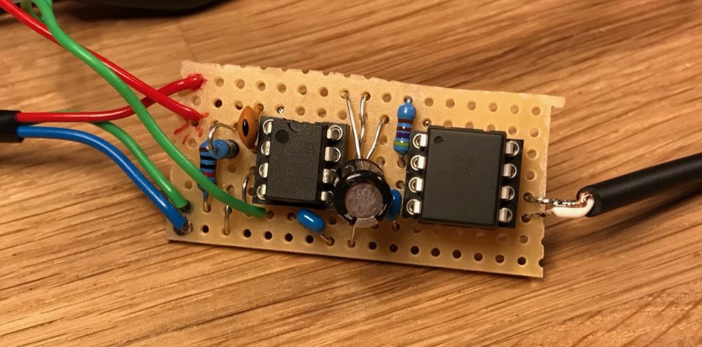
Then, Cordell’s schematic calls for a 2N4091 JFET, a device with a high Idss and low on-resistance, but I couldn’t find any of those. I tried a BF245C, but it wasn’t strong enough. The AGC loop just whacked the gate as far positive as it could go, trying to turn the JFET “more than full on”. So I kept adding more of the things in parallel, until I saw the AGC go negative by a volt or two. I ended up with 5 of them, bodged onto a piece of stripboard.
A J111 would probably have been a better choice. These are the ones Douglas Self recommends as analog switches in “Self On Audio”, and they have a similar 30 ohm Rds(on). JFETs are so variable, though, you never know what you’ll get.
Frequency control with the “Blue Velvet” pot works great! There’s no noticeable amplitude bounce. Well, except for the fact that it’s backwards: anticlockwise to increase. I couldn’t see any easy way to dismantle the pot and reverse the action.
And, first time on the distortion analyser: 0.0015% at 1kHz! π That’s better than the analyser’s own spec.
Stay tuned as we post some pics and stuff the thing into the spare bay of the DA4084.