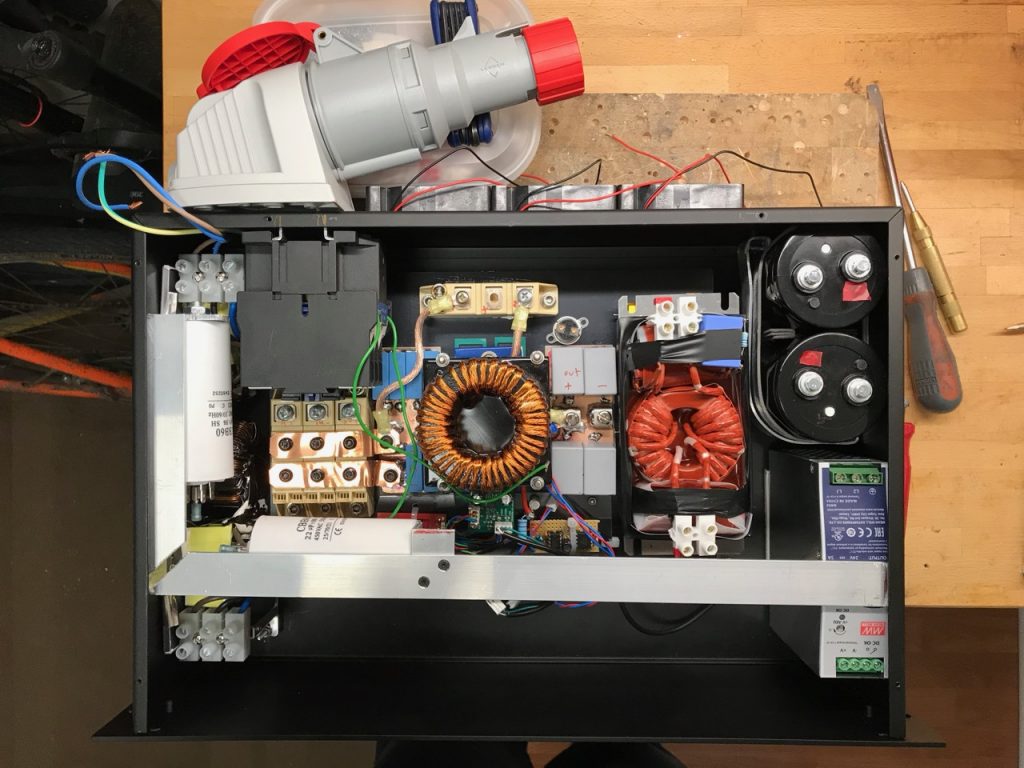
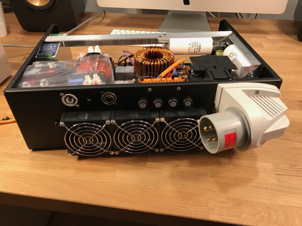
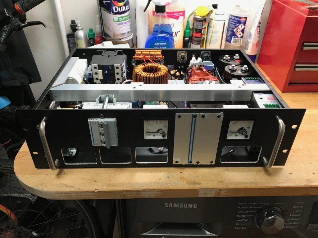
PFC Part 2: The engine

When I started designing I already knew that the heart of the thing would be silicon carbide MOSFETs and diodes. I heard so much from Anders Mikkelsen of Advantics raving about how awesome they are. πŸ™‚

On recommendation from Anders I chose the C3M0065100K MOSFET and C4D10120D diode. These are available from Farnell, Mouser etc. for about Β£10 each. I figured that 2 in parallel would allow me to run an inductor current of 32A RMS, a reasonable match to the mains supplies available in the UK and Europe. Anders also kindly donated an inductor capable of handling 32A RMS. πŸ™‚

The remaining design decisions were set by the dumpster find of a large heatsink and set of 3 Semikron dual diode bricks. Having such a beefy oversized rectifier made short circuit protection easy: I just needed to come up with one more heavy duty diode to bypass the delicate SiC diodes, and then a short on the output would simply pop the circuit breakers on the mains input.

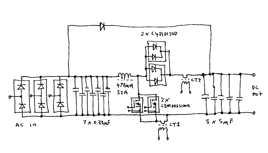
Schematic of the boost PFC engine

CT1 and CT2 are small ferrite cored 1:200 current transformers sensing the MOSFET and diode currents. Their outputs are combined in the controller to give the inductor current.

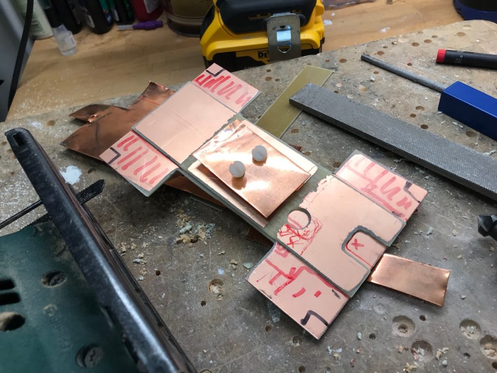
DIY 3 layer PCB πŸ™‚

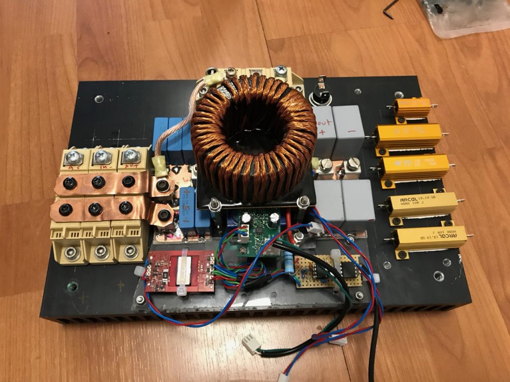
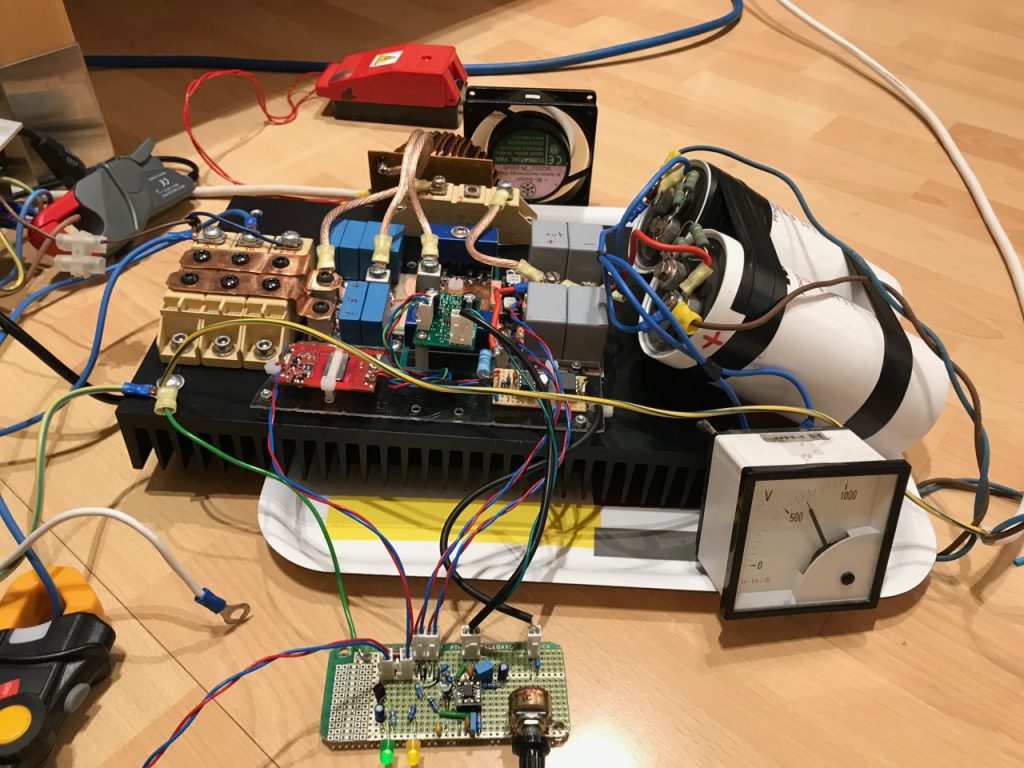
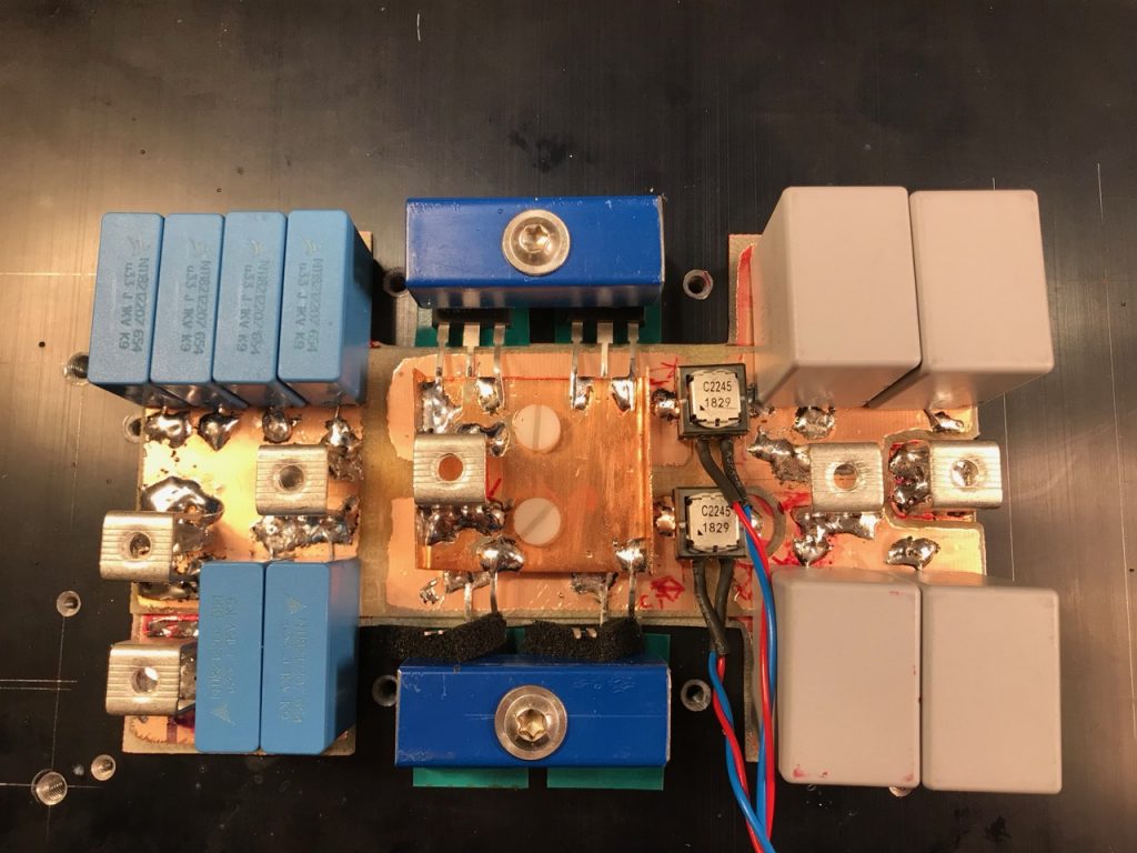
SiC MOSFETs can switch incredibly fast, so a good layout with minimal stray inductance is important. I decided to make a multi-layer structure out of pieces of single-sided copper-clad PCB and copper sheet.

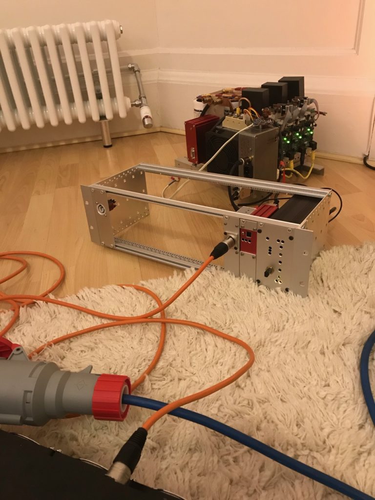
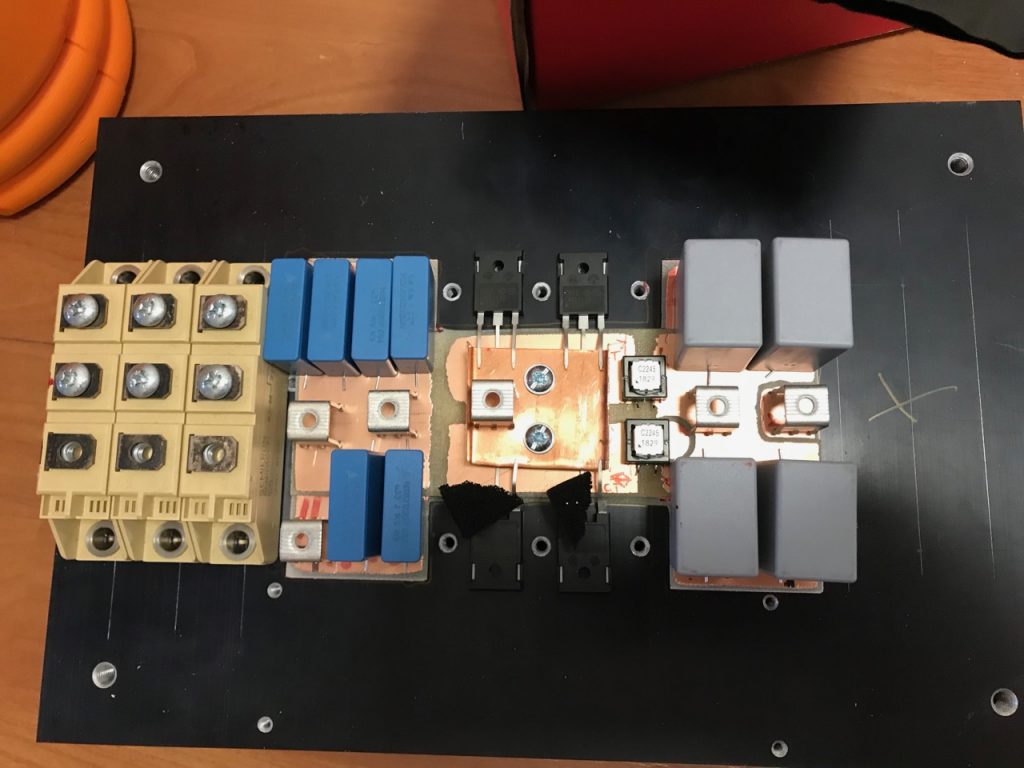
Trial fitment of the components.

I didn’t manage to fit as many capacitors as I wanted: only 5 on the input and 4 on the output. The output ones in particular will have a hard time with serious amounts of HF ripple current. They are only there to filter out the HF ripple. Large electrolytic capacitors will be needed to handle the power frequency ripple, they will be mounted somewhere else and connected by wires.

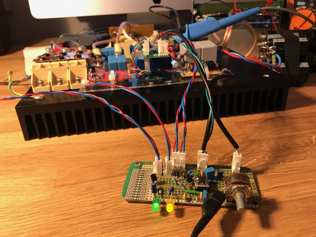
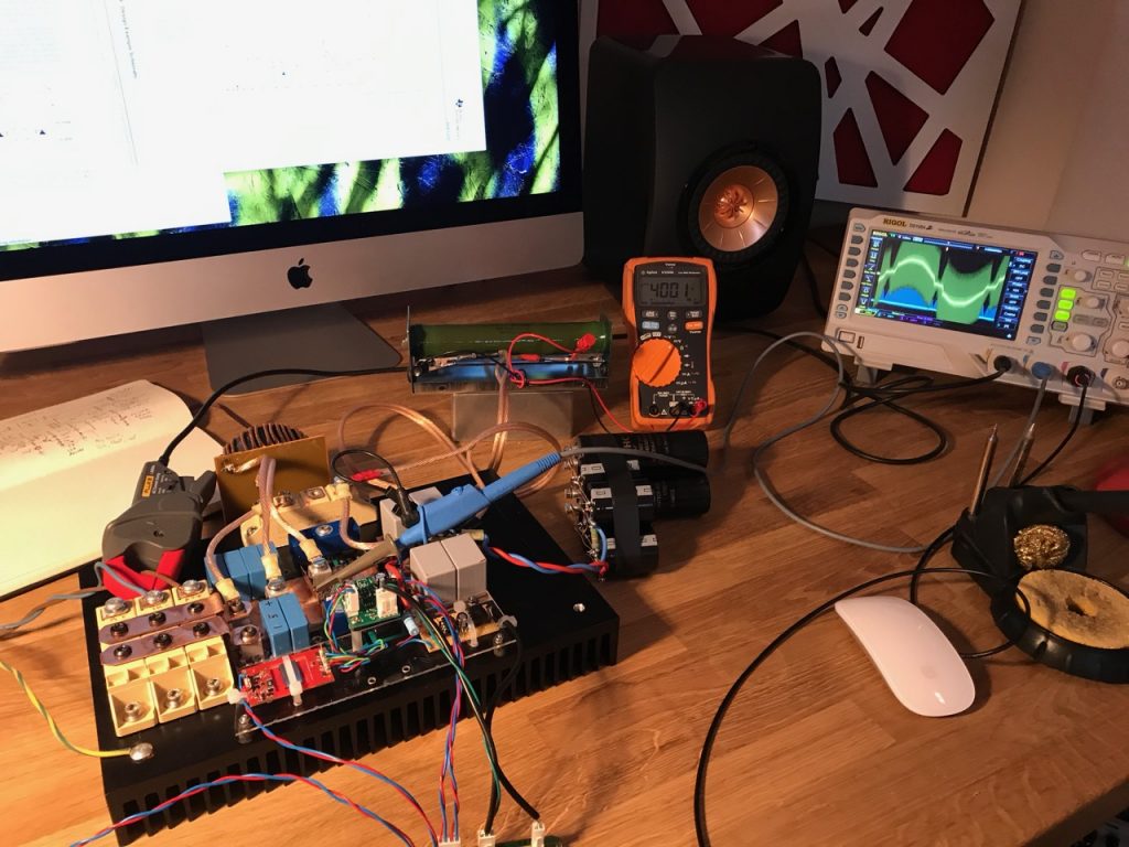
Assembled

Clamps for the MOSFETs and diodes made from pieces of Ikea cabinet legs. πŸ™‚

PFC Part 1: Background

I decided it was time to build a new power supply for Odin with power factor correction. (See all posts on the PFC)

Power factor what? To explain, we have to go back to the turn of the last century and the War of the Currents. Alternating current won so all of our mains supplies are AC. However, solid-state Tesla coils, like most power electronics, run off DC. Odin needs several kilowatts of power at about 750V DC.

The simplest way to achieve this is to use a voltage doubling rectifier on the 240V AC mains. I used this in my previous large solid-state Tesla coil, the OLTC2, with one small refinement. I used SCRs instead of diodes to allow soft starting and varying the output voltage.

The major drawback of this circuit is a very poor power factor, especially at reduced output voltage. It is particularly bad in a DRSSTC, as it has a huge capacitor on the DC bus for energy storage, and the rectifier charges this directly. I improved the power factor somewhat by connecting a large iron cored inductor in series with the incoming mains. This worked well enough, and you can see details of the old power supply here here and here.

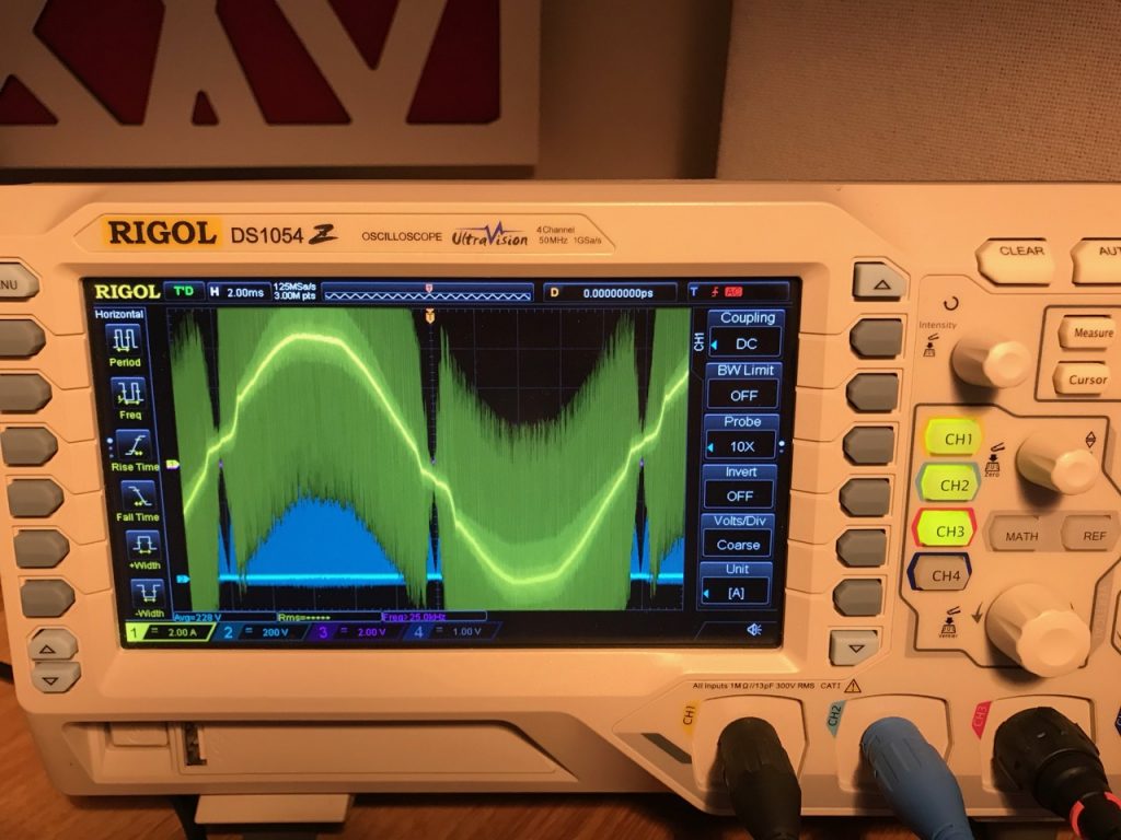
Gate pulses, line voltage and line current waveforms from the old PSU running at low output voltage.

I used this same power supply topology in Mjollnir, Little Cook and Odin. There was no room inside the smaller coils for the passive PFC inductor, so I used a much smaller one, making the power factor even worse. The shortcomings really became apparent in a few shows I did with Odin. It performed really badly when running off a generator, and there were two venues with 3 phase supply that I couldn’t use.

After much thought I decided to go for the simplest possible solution: a boost PFC. These are very common in larger consumer electronics, and controller ICs and design information are readily available. It is also easy to modify for 3 phase input. Essentially you just replace the rectifier with a 3 phase one. The line currents aren’t nice sine waves any more, but the power factor is still greatly improved over a plain rectifier with the same filter capacitance.

Probably the biggest drawback for Tesla coil use is that the output voltage can only be greater than the peak value of the rectified input voltage. You are limited to a minimum of about 400V when running off 240V single phase, and 600V from a 415V 3 phase supply. This is a problem for me at least because I like to check the tuning at reduced voltage after setting the coil up at a new venue.

Eventually I persuaded myself that I could live with this and set to work designing a boost PFC.

Arc Attack x Tesla Fuzz

I built the Tesla Fuzz especially for a collaboration between Arc Attack and some talented metal guitarists. And here they are!

Joe DiPrima and Gabriel Guardian explain how it works

Alex Campbell of Seek Irony performs some neoclassical shredding that makes the Tesla coil sound almost good.
Thunderstruck is on every Tesla guitarist’s set list. πŸ˜‰

Funky light fitting 1

First in a series?

This was made from oak battens, a suspension kit for a 600x600mm LED panel, and lamp holders, cable and ceiling rose from Creative Cables.

I wanted the Edison bulb look, but needed it to run off low voltage due to my sketchy wiring. I found some 12V E27 LED bulbs on EBay, but the choice was much more limited than mains voltage ones, and they had to ship from China. The ones I bought are completely unregulated so the brightness varies drastically with voltage. See Big Clive’s teardown of the same bulb.

I ended up using them in 3 series pairs with a regulated 24V supply from a boost converter hidden in the ceiling rose.

DIY boost converter made with a LM2576HV

12V lighting

One of the joys of living in an old house is dodgy wiring. Another joy is ornate lath and plaster ceilings that might collapse at any minute. πŸ™‚ My problem is a combination of the two. The overhead lights in most rooms are powered by 1930s vintage rubber and cloth covered wiring that can’t be replaced without trashing the ceilings.

As a token gesture to electrical safety, I added a RCD to the lighting circuit, and believe it or not it started tripping at random. This left me with a few options:

Stop using the ceiling lights altogether

Have them rewired and the ceilings replastered

Run the lighting circuit off a lower voltage that wouldn’t tax the ancient rubber and cloth insulation.

A lower voltage would of course limit the power that could be delivered before overloading the wiring. So the second part of the plan would be to replace the light fittings for LEDs to achieve a reasonable light output with less power.

I decided to go for 12V (in hindsight 24 would have been better- I ended up replacing the power supply with a 15V one as a compromise…)

First step was to source a reputable brand of power supply festooned with safety approvals. It will be left on 24/7 unattended, and it would be ironic to go to these lengths to avoid the wiring catching fire, only for the PSU to catch fire. πŸ™‚

I bought a few 600x600mm LED panel lights from TLC Electrical, and chucked the 240V drivers that came with them for some 12V drivers from Ebay.

They are still plenty bright enough.

The power supply was mounted next to the consumer unit and connected to the existing 240V lighting circuit with a FCU.

Oh dear… At this point I realised the thickness of the old wires was mostly insulation and the actual copper cross section was puny. To the point where a 11 amp power supply could potentially overheat them if one of the light fittings shorted out, leaving us no better off in terms of safety than before.

I connected it up anyway πŸ™‚

The first of the new light fittings in place

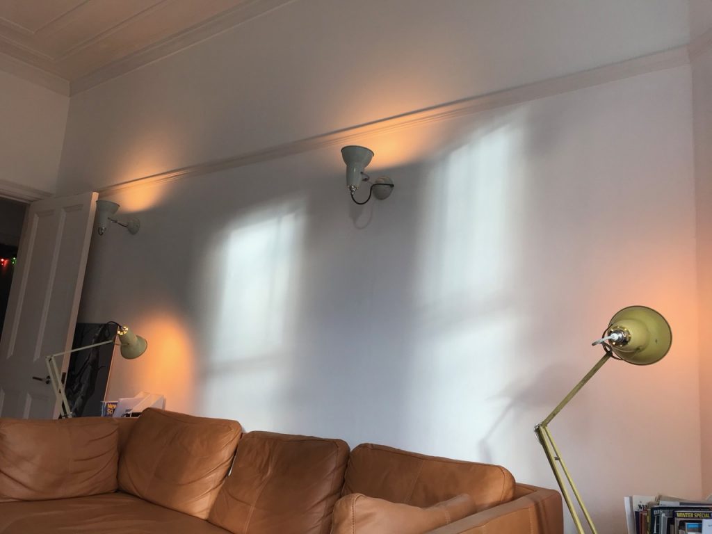
The other light fittings were modified with bodges like this

Later I added some fuses to address the issue of the PSU being able to overheat the wiring.

(footnote: this is still working in 2021 and I made some funky low voltage light fittings πŸ™‚ )

Extra Coneage

8″ speakers never really did anything for me, so I decided to wedge a 10″ into the Ninja Corvette.

It was just possible by carefully chiselling away parts of the cabinet.

It sounds a lot better than the 8″. Unfortunately I have no idea how to make a good grill for it now!