Author: Steve

  • What’s the frequency, Temu?

    [In this episode of The Chinesium Mine we summon the ghost of Jim Williams to help reverse engineer some very bad frequency meters]
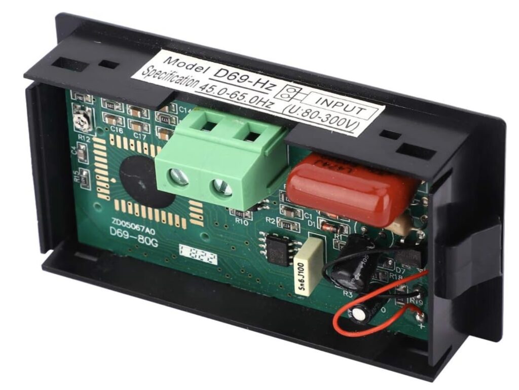
    Back when I had the Lister diesel generator I spent some time looking for a frequency meter for it. I eventually settled on the “D69-Hz” digital panel meter from a questionable eBay store.

    I bought 2 of these meters and was rather disappointed, both examples seemed very sensitive to temperature. And I wanted to use them to measure small changes in frequency in a location that sees big changes in temperature. Bother. The proverbial chocolate teapot (also useless because of excessive temperature sensitivity)

    Out of curiosity I decided to dive a little deeper to figure out just why they were so bad.

    The obvious way to make a frequency meter is to use some kind of timer/counter algorithm to count cycles of the unknown frequency against a stable reference. But that was too obvious for our Chinese designers. This meter uses a frequency-to-voltage converter bolted onto the front of a digital voltmeter.

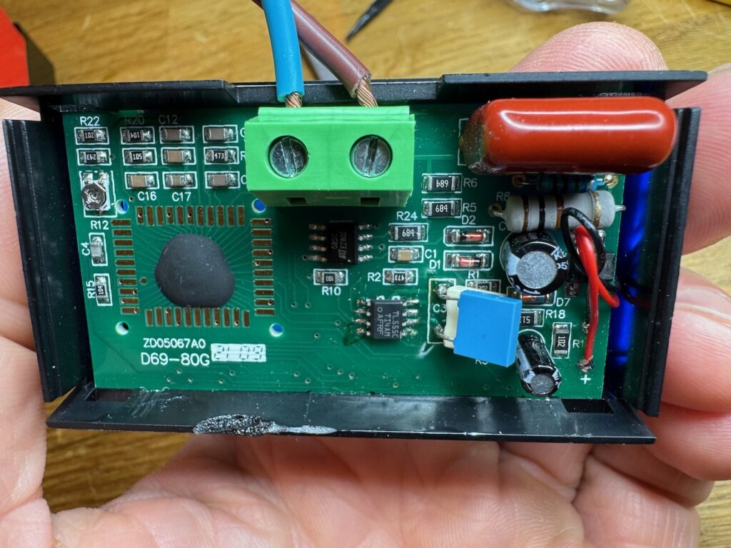
    The F-V converter is a monostable made from a 555 timer chip, that generates a narrow pulse for each zero crossing of the input. These pulses are then averaged by the digital voltmeter chip. Everything runs off a single 3.3V rail, and the 555 timer used is of the CMOS variety, a LMC555.

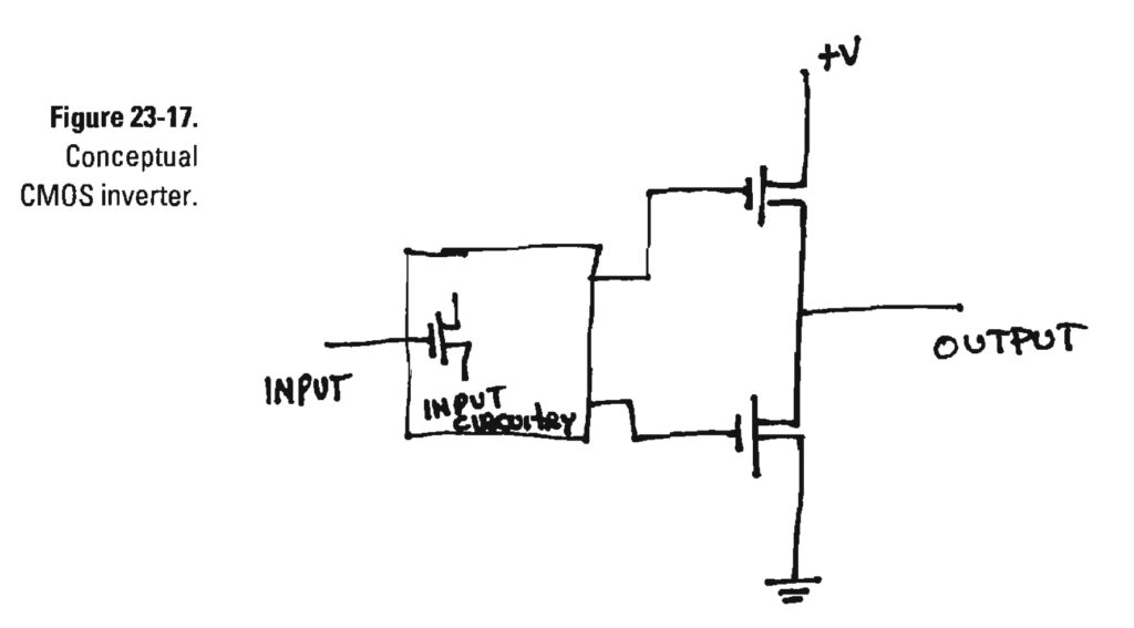
    As the legendary, late Jim Williams explained in his writeup of the “zoo circuit” (see figures 23-16 to 23-18) the output stage of a CMOS digital IC is made of MOSFETs that switch cleanly from one supply rail to the other. There are no Vbe voltage drops like with bipolar transistors.

    Williams was talking about a CMOS logic inverter chip, the 74C14, that he used to squeeze some more performance out of his “zoo circuit” V-F converter. But a CMOS 555 timer chip has the same output stage as a 74C14, and the designers of our Chinese F-V converter used CMOS here for the same reason: to eliminate the error due to the temperature dependency of those Vbe’s.

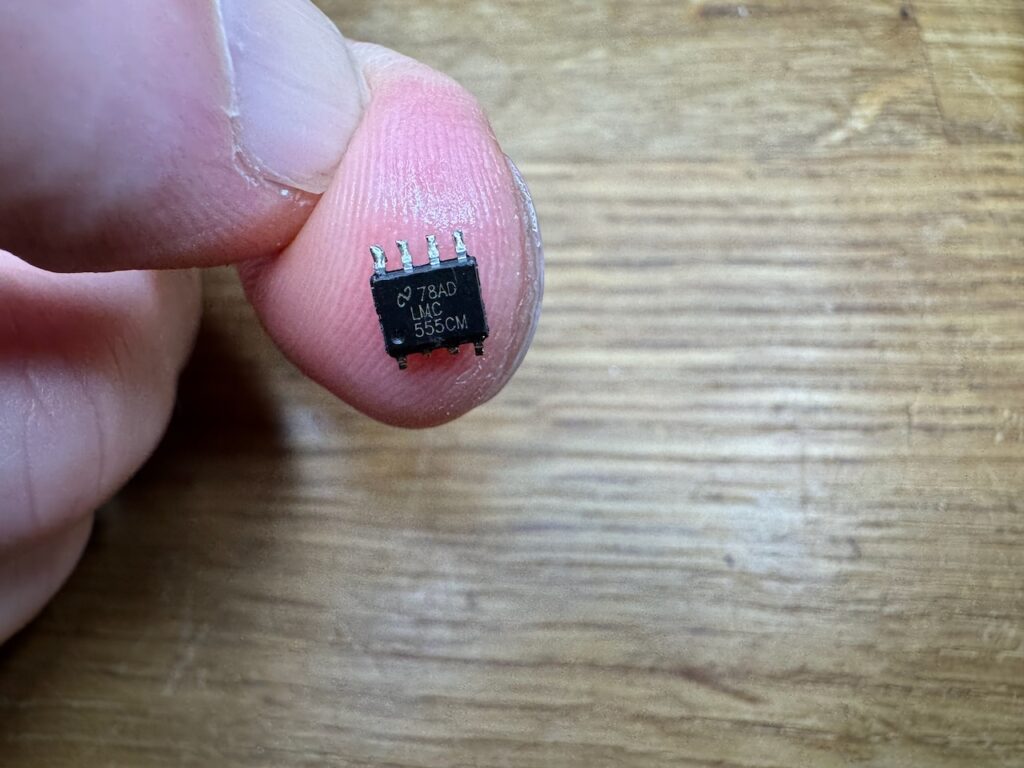
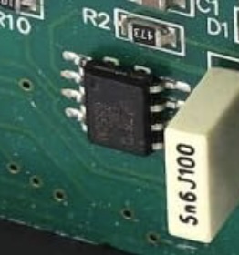
    I scoped the output of my so-called “LMC555” and discovered that it was only putting out about 1.8V peak-peak with its 3.3V supply, and the output increased when the chip was warmed up.

    Hah! a fake! A common or garden bipolar 555 timer remarked as a more expensive CMOS version. By far the most likely explanation for the missing 1.5V of output is two bipolar transistor junction voltages at 0.7V each. The 555 timer internal schematic on Wikipedia shows a Darlington pair for the high side of the output stage, so that would be our two Vbes right there. The low side is a common emitter, which would only drop a few hundred millivolts.

    I yeeted the counterfeit chip out of there and substituted a TLC555 (which happened to be the cheapest CMOS 555 timer in Farnell’s online store at £0.66)

    C3 is the monostable timing capacitor, I had to change it from 5.6nF to 3.2nF to reduce the pulse width in compensation for the increased output voltage of the new 555 chip.

    Having done this, R12 was tweaked to read 50.0Hz with a mains frequency input at room temperature. Most Chinese meters I’ve seen so far have a “fortune trimmer” like R12 that can be twiddled to give almost any answer you want. I don’t think I even want to know the tolerance or tempco of this part.

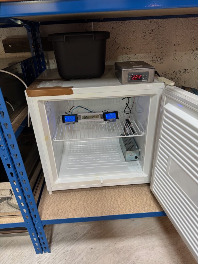
    My modified D69-Hz seemed much more stable, so I put it in the Hayburn Labs environmental chamber alongside an unmodified one and a thermometer.

    The environmental chamber is not a precision instrument (actually it’s a freezer from a charity shop) but it’s still incredibly useful for freezing and boiling prototype circuits to discover any temperature-related quirks before the customers do.

    The mains frequency varied by more than I expected during this experiment, due to those meddling wind turbines. I had to go and look up the actual National Grid frequencies corresponding to the photo timestamps.

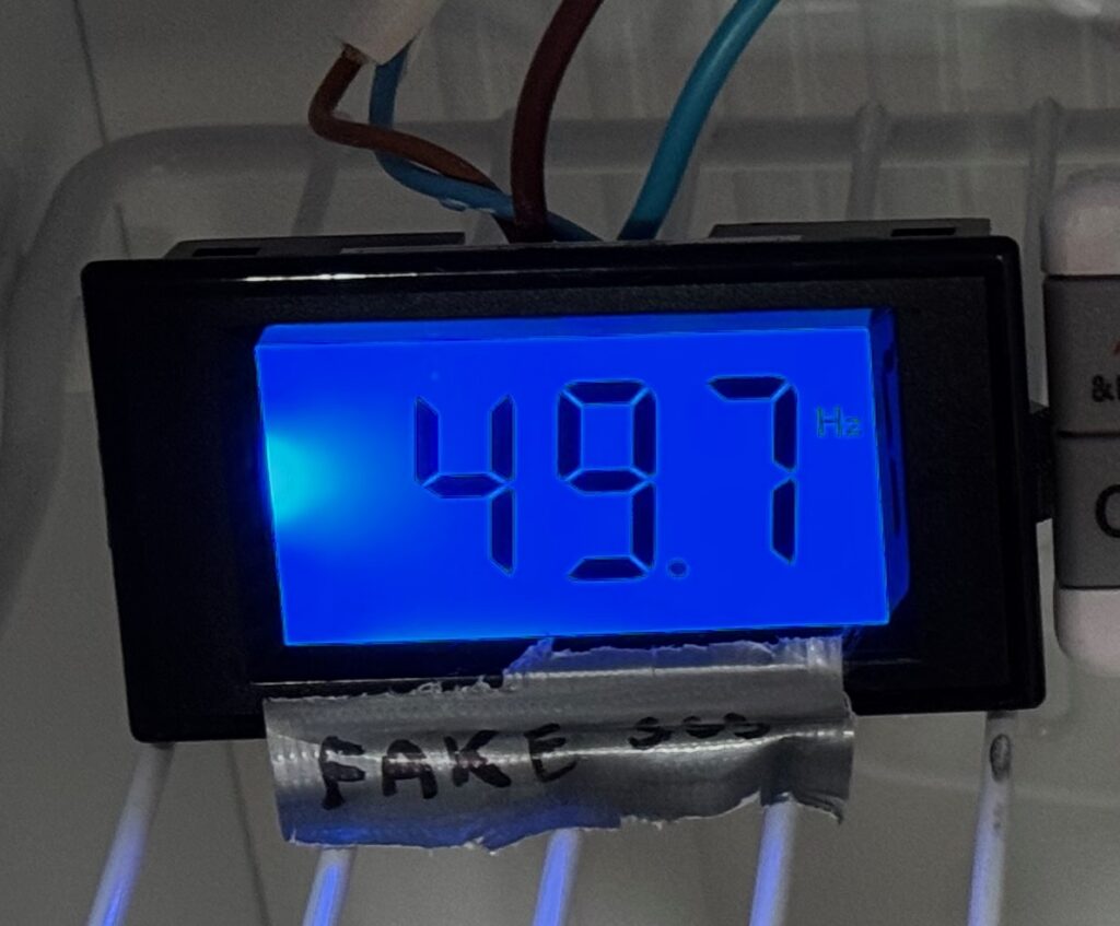
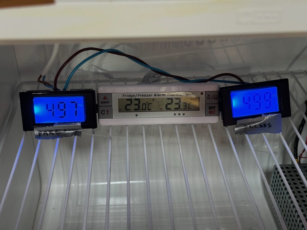
    At 23C the meters read 49.7 and 49.9. National Grid official value was 50.111Hz so our modified meter is reading 0.211Hz low.

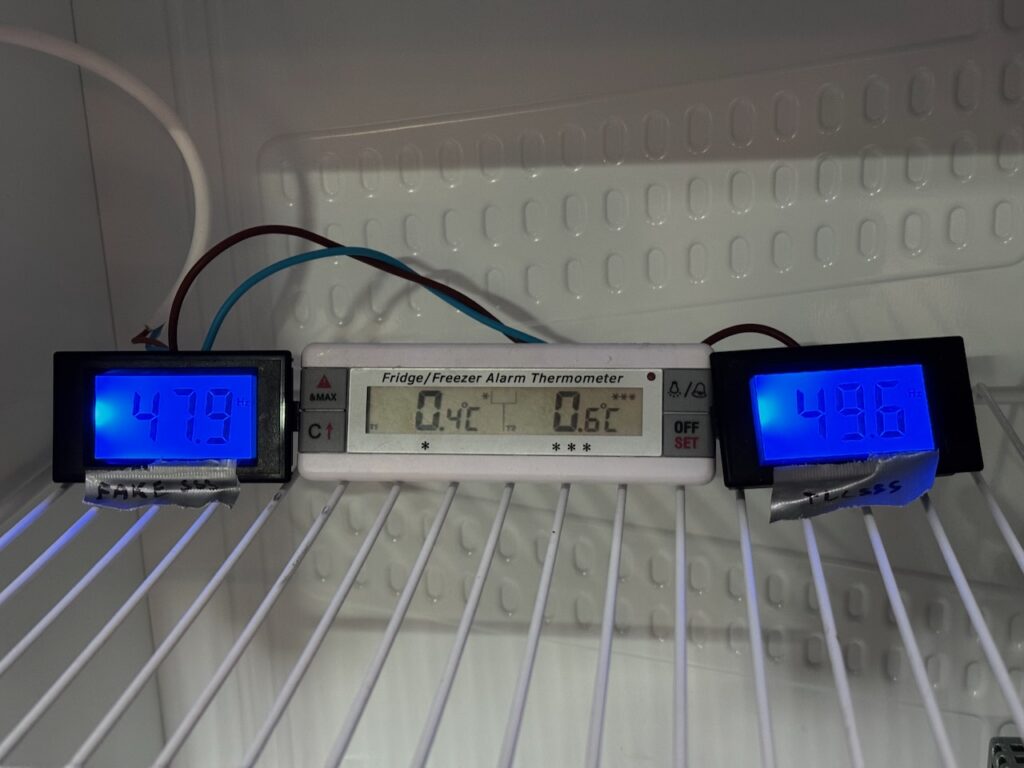
    After refrigerating to 0C and allowing some time for temperature to equalise, the stock meter gave a reading of 47.9 and the modified one 49.6. Actual mains frequency was 50.041Hz so the modified meter has an error of -0.441Hz.

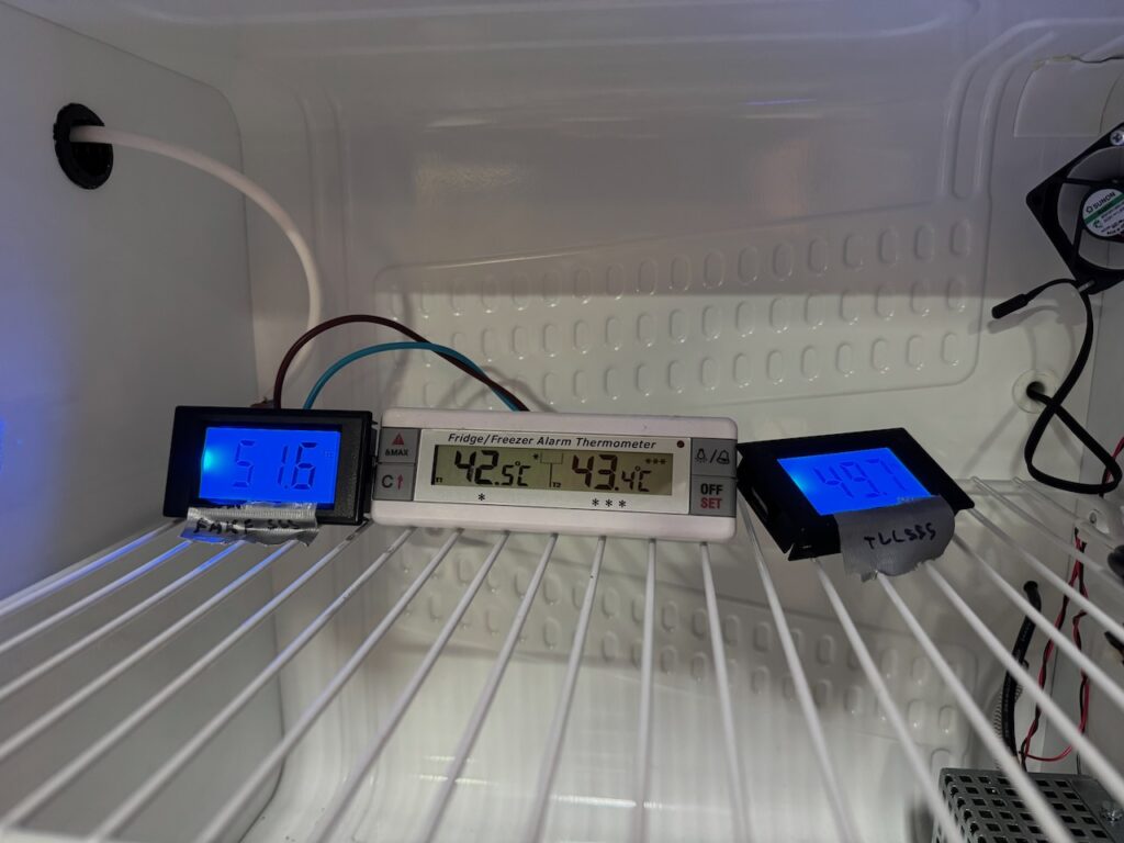
    Stewing at 40C for 20 minutes produced a result of 51.6 for the fake 555 and 49.7 for the TLC555. Actual mains frequency was 49.881Hz so the modified meter error is -0.181Hz.

    So over the 0-40C temperature range, we have an error of 3.7Hz (7.5%) for the unmodified meter and 0.26Hz (0.5%) for my modified one.

    Conclusion: When I originally tested the Lister diesel, it gave a frequency of 51.25Hz unloaded and 50.00 on full load. And the temperature in Container Labs varied from below zero, to over 30C. The error with temperature of the unmodified meter would be more than twice the generator’s actual change of frequency, so it would have been completely useless.

    By replacing the fake 555 chip, we reduced the temperature sensitivity by a factor of 15. But the error still works out as 20% of the frequency range covered by the Lister diesel.

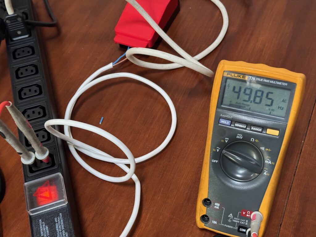
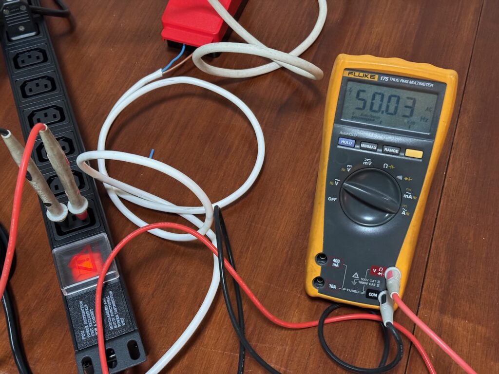
    As a check I got out the same Fluke meter that I originally used to test the generator. It agrees with the National Grid website to within 0.01Hz.

    (National Grid official value was 49.854)

    (National Grid official value 50.034)

    With this level of accuracy, I guess Fluke’s budget must have stretched to an actual quartz crystal in there somewhere, to give an accurate reference for a frequency counting algorithm. Our poor D69-Hz meters probably have a RC oscillator for the clock.

    You can still buy the D69-Hz on Amazon, if you’d like a more laborious way of wasting money than simply setting fire to a £10 note. Believe it or not, I don’t earn a commission if you buy through this link. 😀

    The 5.6nF capacitor and phoney “LMC555CM” are visible in the product photo, so I’m pretty sure it’s the same Shenzhen Chocolate Teapot Industries product.

    Rating: 1 Zhong out of 5

    🀄️Depleted Chinesium
  • Diesel never work

    [But it did. Extending your diesel heater control panel]

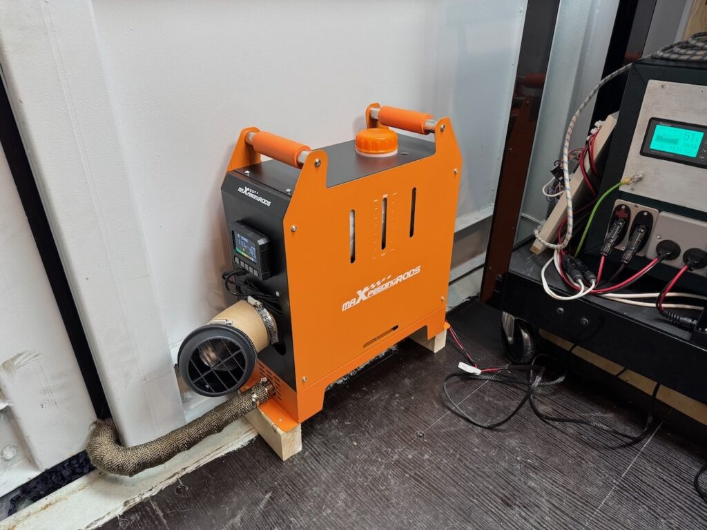
    When I moved into Hayburn Labs, the diesel generator had to go, but my trusty (ish) MaxpeedingRods diesel heater came with me. I thought it was worth keeping as the running cost is about half of an electric heater.

    There are dozens of brands of these devices, all Chinese clones of the Webasto air heater, priced at about one-fifth of the real thing. The real Webasto and Eberspacher heaters are sold as bare units for permanent installation in a vehicle, with the combustion air inlet and exhaust routed directly to the outside. But some Chinese entrepreneur came up with the idea of mounting the whole system together with its fuel tank into a portable box, with the combustion exhaust through a short length of pipe to nowhere in particular. This package proved quite popular and it’s now even possible to buy a European made version, the Autoterm Travel Box 2.

    Mine must be one of the better clones as it hasn’t caught fire or gassed me with carbon monoxide. Yet.

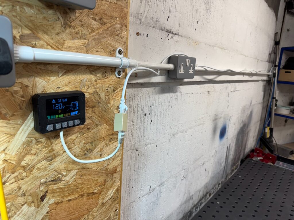
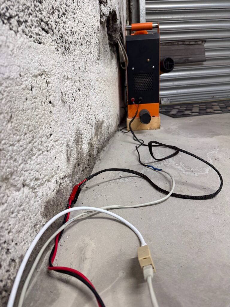
    For now combustion air is drawn from inside the building, and the exhaust pipe is poked through a hole in the wall. As I’m doing the place up (and making it more airtight) I plan to relocate the heater outside for safety, and it would be nice to extend the cable that connects the heater to the control panel. I haven’t seen much information about this online, so I’m documenting my experiments here.

    According to the intertubes, all of these heaters have a 3 wire connection with a low-speed digital data link similar to the automotive LIN bus.

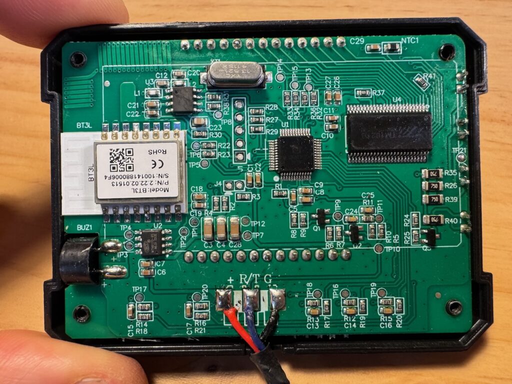
    On opening the control panel, sure enough I found 3 wires marked +, R/T, and G, which I guess are positive supply, a bidirectional data line (Receive/Transmit?) and ground. Real LIN uses 12 or 24V for both power supply and signalling, but according to the manual, this is 3.3V. (yes it has a printed manual in legible English)

    You can see from the PCB that it has both Bluetooth and 433MHz wireless remote functionality, and it came with a remote that works, so why am I even bothering to extend the wire? Well the temperature sensor for the thermostat functionality is on this board. Probably “NTC1” in the top right corner. So I think it makes sense for it to be in the main work area.

    I unsoldered the three wires from the control panel PCBA, snipped a Cat5 patch cable in half and attached the two half-cables with the following colour code:

    Signal nameMXR wireCat5 wire
    +RedOrange, orange/white
    R/TBlueBlue
    GBlackAll other wires

    As a Cat5 has 8 cores, I had 5 left over so I used several in parallel for the positive supply and ground. I thought this would help with voltage drop and noise pickup if it really does use 3.3V levels.

    I plugged the two ends together with a RJ45 coupler, and the panel lit up and still seemed to work. So for my next test I interposed a 15m Cat6 Ethernet cable.

    It still worked…

    Discovering what happens when the control panel is unplugged with the heater running is an exercise for the reader. A reputable manufacturer like Webasto would of course have tested this and made sure it went through its normal cool-down and shutdown sequence. I wonder if the Chinese clone makers have that much attention to detail.

  • Buds

    They’re wrong
    Those buds
    Your bod

    It’s bad
    It’s not a gift from God

    The blood,
    the curse unchecked will burgeon
    I’ll buy you time to think
    -Your surgeon

  • Terrible! Tantalising! Tektronix!

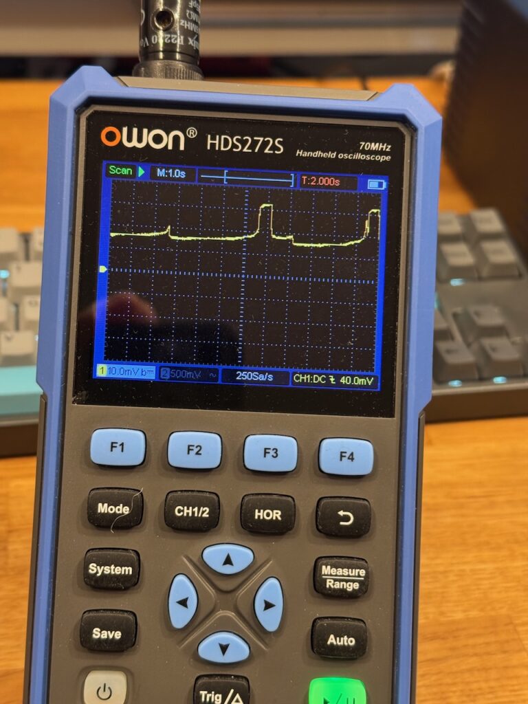
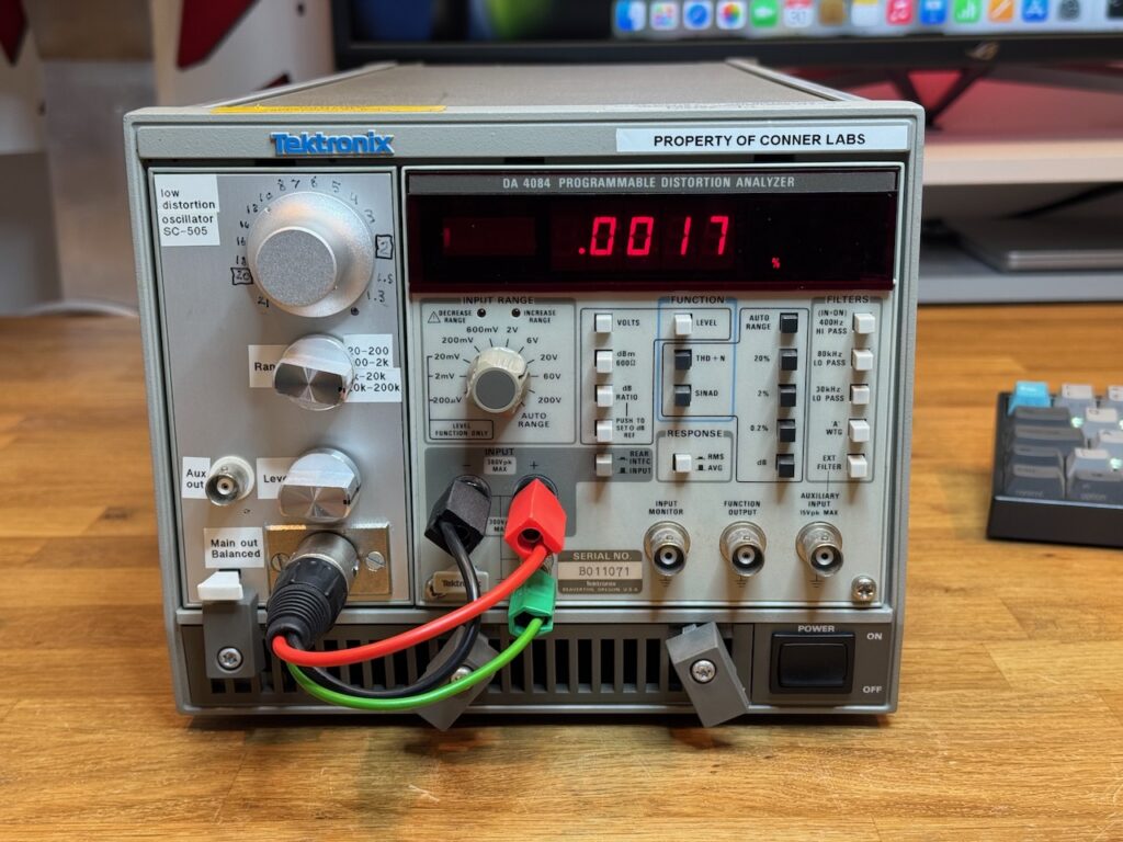
    I’ve been doing a bit of work on audio amps lately, so it was a bit annoying when my Tektronix distortion analyser suddenly died.

    With a very distinctive smell. I try to avoid using tantalum capacitors in my own designs, so it was one I hadn’t smelt in a while. The older tantalum beads were somewhat unreliable, with a tendency to fail short circuit, crack open and spew their metallic innards in a way that always reminded me of the egg from the first Alien movie.

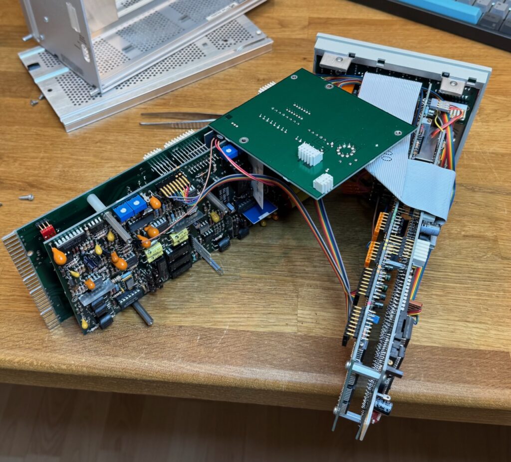
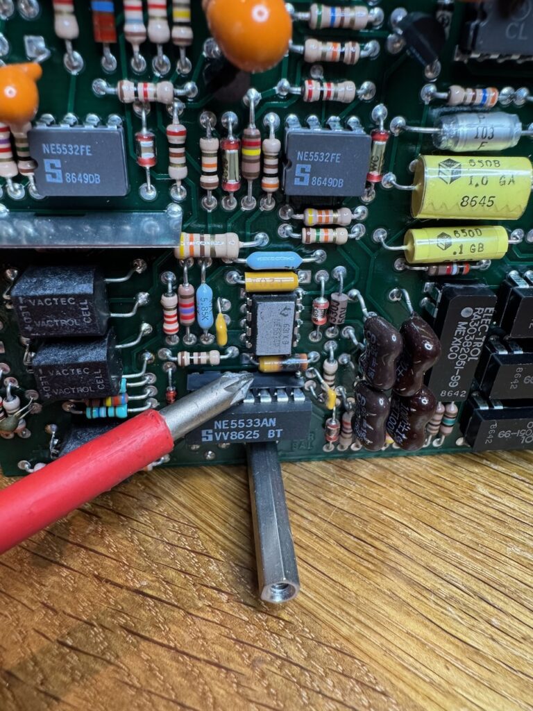
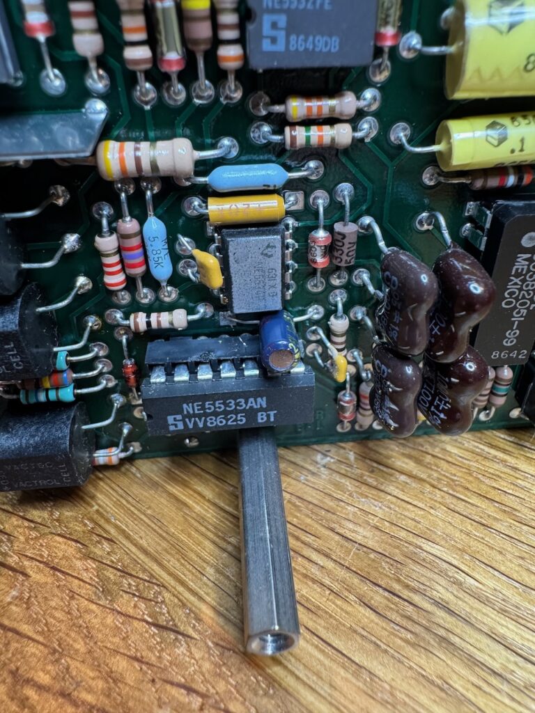
    The innards of the DA4084 are a sandwich of multiple circuit boards connected by random wires, and a bit fiddly to dismantle. And of course the obviously burnt tantalum capacitor was right in the middle of the sandwich.

    I guessed it was used for decoupling and the value wouldn’t be critical, so I replaced it with a 10uF electrolytic.

    Normal service was restored…

  • Wrong Side of the Thermaltracks

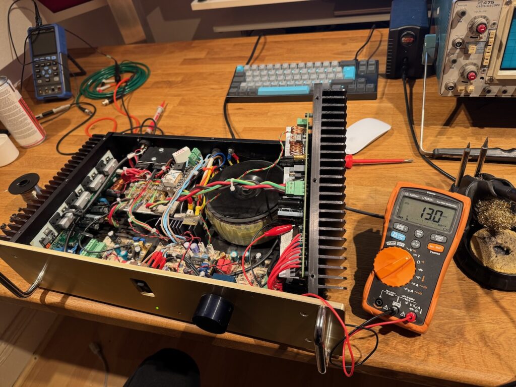
    In 2011 I built the Selfless Amp, my first hifi power amp designed from scratch, albeit very strongly influenced by Douglas Self.

    I also used it as an opportunity to try the then-new ThermalTrak power transistors from OnSemi. These have a temperature sensing diode co-packaged with the transistor, which promised to eliminate all biasing hassles.

    More recently I noticed the right channel heatsink was getting a lot hotter than the left channel. The problem would come and go, and a few times I reset the bias only for it to become too cold later.

    I ran it for ages like this but eventually got the time and inclination to get to the bottom of the issue. Prodding the circuitry with a stick and bending the circuit boards made no difference, so loose connections were ruled out. And the fault followed the output stage board when parts were swapped between channels. Therefore it was most likely either in the driver transistors, bias generator transistor, or one of the output devices.

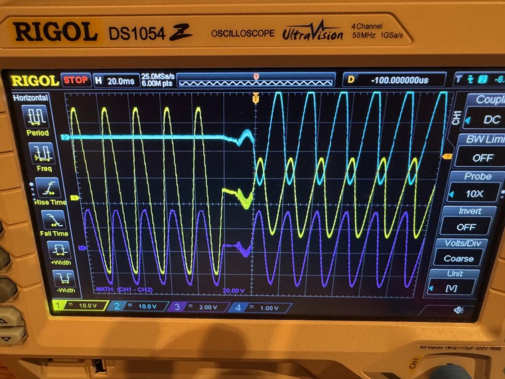
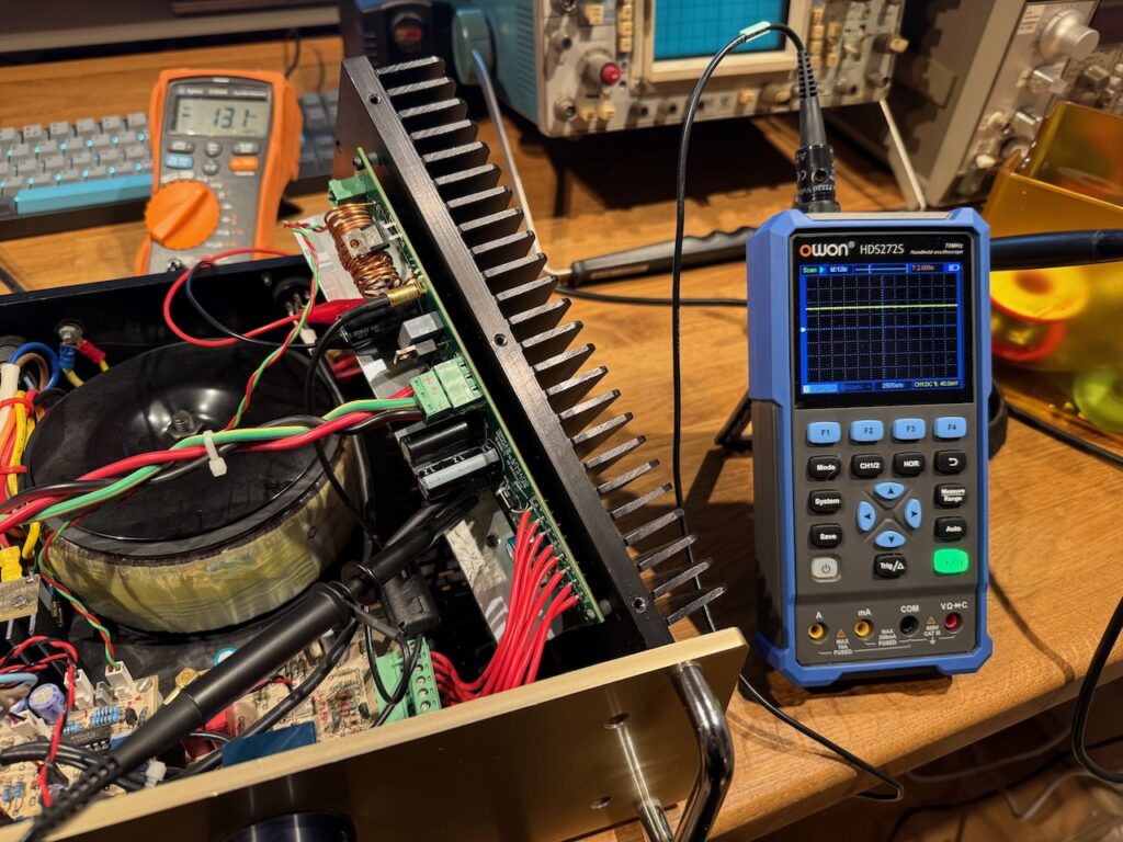
    Connecting a scope in roll mode across one of the emitter resistors, I could see the quiescent current jumping around at random.

    I tried replacing the driver and bias generator transistors (Q1 and Q3 in this schematic) but it made absolutely no difference. At this point I also noticed that the jumps in quiescent current could be seen across all of the emitter resistors. If the problem was in an output transistor, I’d expect it to only affect a single device.

    This pretty much narrowed it down to an issue with the ThermalTrak diodes, so my next move was to replace Q4 and Q5, the pair of output devices whose diodes are used for bias generation.

    Stability was restored.

    I have seen faults like this in the past where semiconductor junctions would develop temperature sensitive behaviour over and above the usual -2 millivolt per kelvin. The late Bob Pease wrote about a batch of diodes he came across that acted as thermostats, going open circuit above a certain temperature. This seems to be a less extreme version of the same thing, where the forward voltage of the ThermalTrak diode jumps around at random by 10s of millivolts as the temperature ramps up. I’m an applications guy, not devices, so I don’t know the semiconductor physics behind it. My guess would be bad packaging putting a temperature dependent mechanical strain on the device.

    The NJL4281/NJL4302 devices I used are end of life, but similar parts are still available.

  • The Shooting Lodge

    At dawn, a gosling stands upon the lake
    He doesn’t fly or swim
    He’s fake
    He’s driftwood?
    Grains, or bars upon his wings?
    There’s things suspiciously like other things

    Five times a day the trains
    From London mostly, Edinburgh and Wick
    Disgorge their loads of promises and pains
    The visitors come fast
    And thick

    They chafe at their disguise
    They groan
    Forlorn, they stumble over stones
    And underneath the surface cables hum

    The cameras are tucked from view
    The Starlink dish is new
    A winch to drag the carcasses
    A gun

  • Project Dino-Solar 240

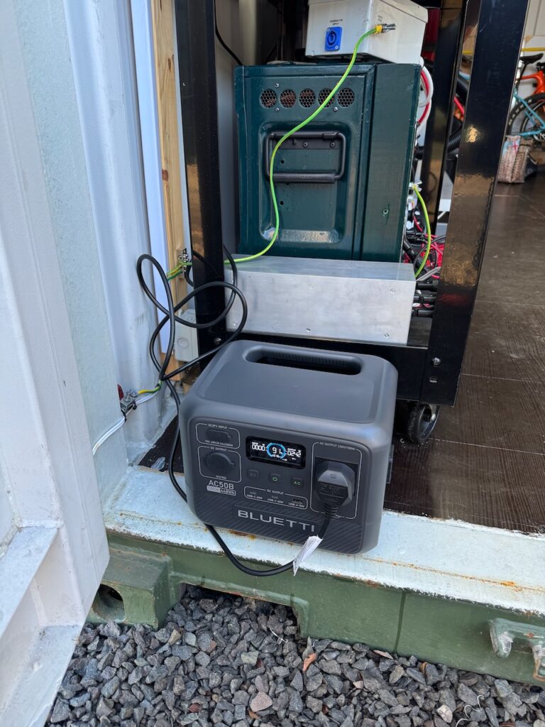
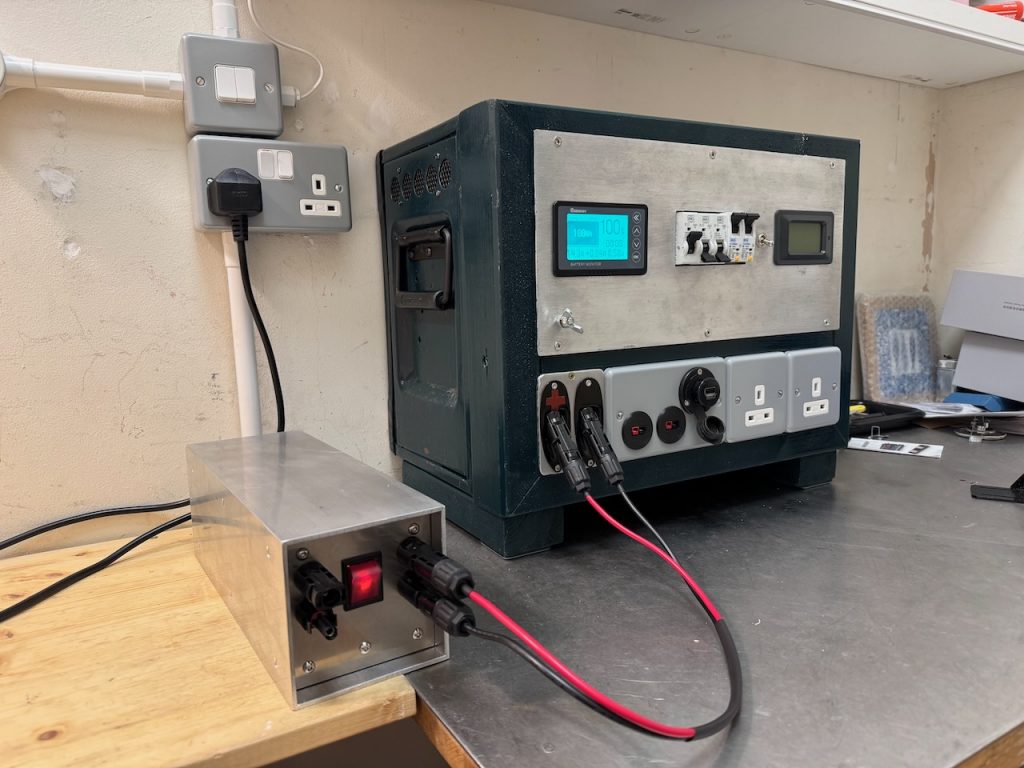
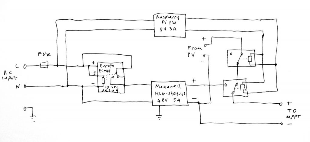
    A gadget to charge the Power Tank off AC power.

    The Power Tank uses a Victron MPPT 75/15 for battery charging. I experimented with this and found that it would happily charge from a DC power supply connected to the PV input.

    I tried several different bench power supplies and also 18V DeWalt cordless drill batteries, and all seemed to work fine. Victron specify that the DC input voltage has to be at least 5V above battery voltage for the charger to start, and then 1V greater for it to continue running, so in practice 24 or 48V DC would be a good input voltage for my 12V system.

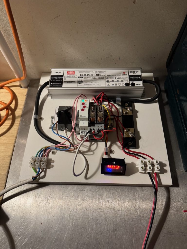
    I settled on a Meanwell HLG-240H-48A LED driver obtained cheaply on eBay, that supplies 48V DC at 5A.

    This worked just fine plugged directly into the solar input, but I decided to complicate things by adding an automatic changeover between solar and AC charging when AC power was present. My first attempt was to use a couple of diodes to OR the solar and PSU inputs, but this didn’t work. The PSU would be dragged into current limit as soon as it was turned on, and the MPPT would then ramp its output voltage up and down searching for a max power point and never find it.

    The key to a successful changeover turned out to be to disconnect the solar panels, wait 5-10 seconds for the input voltage to fall to zero and the MPPT to shut down, and then connect the power supply. I made a circuit to do this automatically depending on the presence of AC power.

    This junk box inspired design is based on a Europa ECMFT timer relay, and a Raspberry Pi 4 wall power supply that I’d previously cut the DC plug off for some reason. When AC power becomes present, the Raspberry Pi wall wart supplies 5V to a changeover relay, that disconnects the MPPT positive input from the solar panels and connects it to the 48V DC PSU, which is still turned off. After 10 seconds the timer relay switches the PSU on.

    When AC power is lost the reverse happens. The 48V PSU turns off straight away, while the Raspberry Pi PSU keeps the changeover relay energised for a few seconds on its stored energy. This avoids the changeover relay having to break the 48V while current is flowing.

    The main weakness of this circuit is that it uses a relay to break and make the DC output of the solar panels. Relay contacts typically have much reduced DC ratings compared to their AC rating, and most won’t even handle more than 30V DC.

    This isn’t a huge problem, if there was lots of solar power available, why would I even be switching over to AC charging? Also my solar array is tiny and puts out less than 30V DC. However, I paid it some lip service by choosing a relay with a 30V DC rating, and putting two of them in series on the PV side. (What if the 2 relays don’t open at exactly the same time I hear you ask? Next question please…)

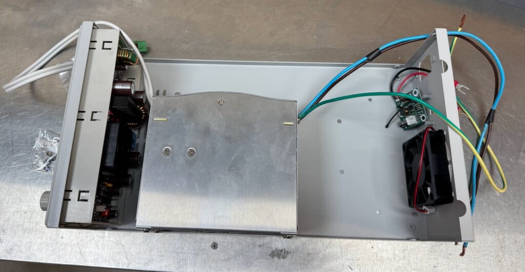
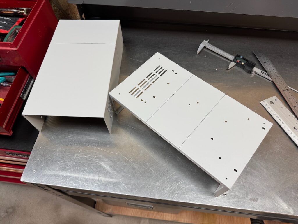
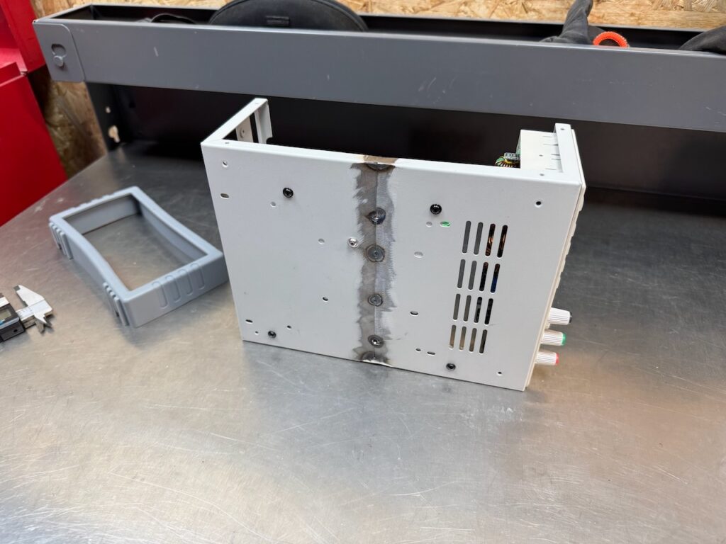
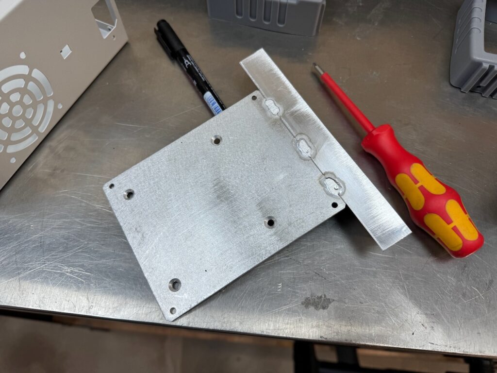
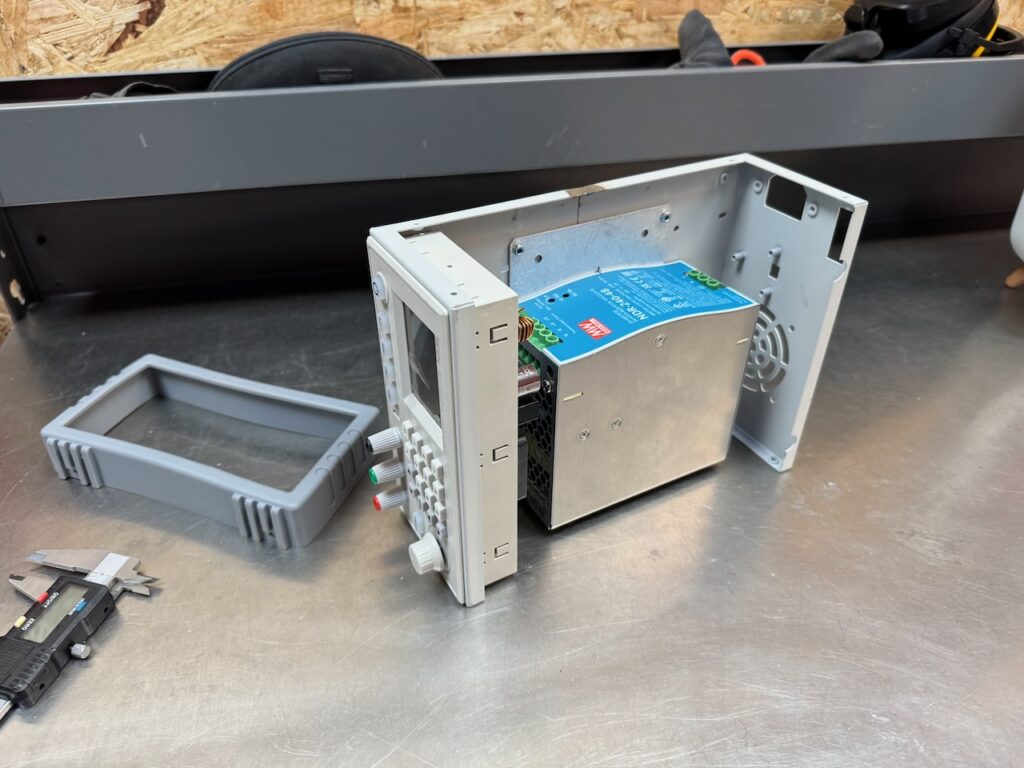
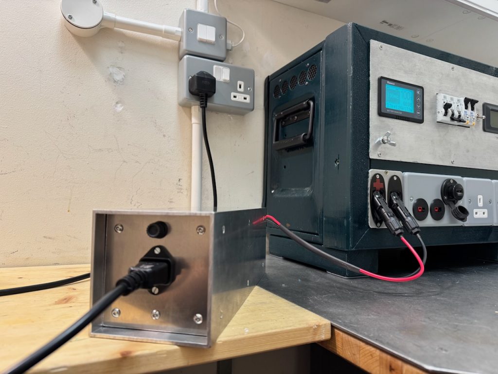
    I tried a new enclosure construction technique for this, based on a piece of 4″ x 4″ aluminium box section. The ends are made of sheet aluminium and attached to the box section by aluminium angle. The HLG-240H-48A is screwed to the case with a generous amount of heatsink compound to help it lose heat by conduction, which it seems to manage OK.
    You might notice that the prototype had a digital voltage and current meter which is now gone. This cheap Chinese meter turned out to be basically a random number generator so I ditched it.

    I think it looks great, but the wiring was a real pain and ended up very messy inside, because it all had to be done through the ends. I’m not sure I’d use this technique again unless the innards could be made to slide out as a single unit. That wasn’t possible in this case because of the power supply covered in heatsink grease.

  • Project Happy Welder 3000

    [Documenting the happy outcome]

    This was a long-running project to get my welder running off the Lister diesel generator. After a few dead ends it is now officially finished and has become a piece of workshop equipment for day-to-day welding of other things.

    It ended up split into two sections which I’ll call the Happy Welder 3000S and 3000T. The division was a bit arbitrary and was really about letting me reuse salvaged enclosures from my junk heap.

    Happy Welder 3000S

    The “S” stands for switch box or splitter. The main purpose of this part is to split the incoming supply from the generator into two. One feed goes to the welder and the other to a selection of “dumpable loads” which are switched off while welding is in progress.

    The motivation behind this is to keep a decent amount of load on the engine most of the time. Diesels like to work and will get clogged up with soot if left idling for long periods of time. And the nature of welding is short periods of high power draw with long breaks in between. (at least at Container Labs it is, I’m not planning on building a ship any time soon)

    I fiddled with a few different schemes to turn off the dumpable loads by sensing the supply current draw of the welder, but couldn’t get this to work reliably. So I modified the welder slightly. It has a solenoid operated gas valve inside that supplies argon to the torch while welding. This opens a second or two before the arc is struck and stays open for about 20 seconds after it goes out. Just perfect for actuating a load dump contactor.

    Using some zip ties and piggyback spade terminals, I connected a relay in parallel with the gas valve operating coil. This runs off 24V DC so finding a suitable relay was no problem. To save drilling a hole* in the welder I repurposed the 3 unused pins on the foot pedal connector. I do have a foot pedal, but it plugs into the hand controller socket on the front panel.

    * another hole- the eagle-eyed might notice that I’ve already replaced the captive power cord with a Neutrik Powercon inlet. I love Powercons 😀

    Schematic of Happy Welder 3000S

    I wanted a low voltage signal for triggering the load dump contactor. The relay I added inside the welder is quite capable of switching 230V, but the foot switch plug has male pins that could deliver an electric shock when unplugged if I used mains voltage here. So the finishing touch was a small low voltage power supply inside the 3000S enclosure just for the contactor coil. I used a 12V switched mode wall wart with the pins trimmed down and a piece of plastic attached with hot glue to insulate the stumps.

    The CPC catalogue turned up an inexpensive 20A contactor with a 12V coil and normally closed contact, and the 3000S was done.

    In use the “dumpable loads” are two battery chargers feeding the Power Tank, and an electric heater. The 3000S also serves as the earthing point for the generator and everything connected to it.

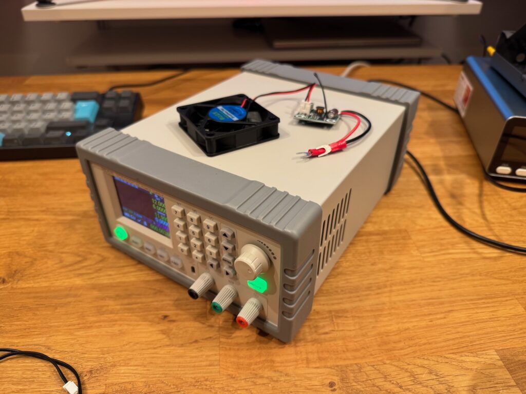
    The battery chargers are modified switched mode power supplies which I’ll write about another time. In the bottom right you can see my long-suffering Astec LPS250 which started life as 5V, 50A, and is now cranking out 30A at 14.4V. Not bad for a “250W” unit, do I smell burning? :/

    Happy Welder 3000T

    T is for transformer. This box (a Pentium 4 PC in a previous life) contains all of the parts that I found were needed to make the welder accept Lister’s quirky retro power quality. I already had this enclosure in my junk pile and it fitted perfectly under the workbench. I pondered trying to squeeze the 3000S parts in here too but decided it would be a wiring and assembly nightmare.

    Schematic of Happy Welder 3000T

    The most important part (as determined by trial and error) is a 2.1kVA autotransformer that steps down 230V to 190. I believe this was originally used to reduce the voltage to street lighting in the early hours as an energy saving measure.

    The box also contains a bridge rectifier, capacitor and power resistor (sold as a 230V, 100W cabinet heater) the purpose of which is to draw lots of current on the voltage peaks and squash them down a bit further. This was the final bodge that allowed me to max out the generator’s engine power without any overvoltage trips. Hopefully it should also protect the 12V power supply inside the 3000S from destruction by excessive peak voltage.

    A small fan on the rear panel blows air over the transformer, before it exits through the resistor. This is really a must as the resistor is dissipating about twice its rated power.

    The fan was also salvaged. I can’t remember what it came out of. I had a fun afternoon making front and rear panels out of pieces of scrap metal.

    The first of hopefully many happy welds. (proof that a weld doesn’t need to be Insta worthy to be happy 😀 )

  • Fixing EMF carnage part 2

    With the PFC sorted I turned my attention to the main coil unit. I started by replacing the melted tank capacitors. One had exploded, one looked a bit burnt, and the leg of a third capacitor came off in my hand.

    Out of curiosity I cut open the exploded capacitor. The whole inside was just a blackened mess.

    I bought a load of these Cornell Dubilier 942C series capacitors, 1uF 1000V, years ago for the OLTC 2. In Odin they are overloaded to about 3x their rated RMS current and crammed into an unventilated wooden box, so I’m not entirely surprised they failed.

    What did surprise me was that every other capacitor tested fine! I found replacements for the destroyed caps in my pile of Tesla junk and the capacitor bank was ready to go again!

    Inspecting the rest of the circuitry, the only other problem I could find was a shattered transistor on one of the gate drive boards, which looked like it had been mechanically damaged while taking the unit apart.

    After a few days’ wait for Farnell to deliver a replacement, I headed to the container and set up all the parts of Odin minus the secondary coil for a dummy load test.

    Unfortunately something wasn’t right, the primary current was well below what it should be, and the “Power Fail” LED lit up every time the fire button was pressed.

    Suspecting a wounded IGBT brick that was drawing a lot of gate current and overloading its gate driver, I took the bridge apart and tested everything, but the IGBTs seemed fine! All the resistance and diode tests checked out, and a 9v battery turned them on and off happily.

    Using Banggood’s finest thermal imaging camera (80 x 60 pixels resolution!) I could see that something on one of the gate drive boards was getting exceptionally hot.

    It turned out to be a shorted diode in the gate drive board’s power supply that was causing the voltage to sag horribly and trigger the undervoltage lockout. UVLO is really important in this application where we are driving IGBTs well over their rated current. Trying to pass the full current with insufficient gate voltage will result in a big bang. Luckily the UVLO did its job today and there was no bang.

    With the diode replaced, the Power Fail light went out and the gate waveform looked “just perfect” as Allen Millyard would say.

    This looked encouraging so I put some DC bus voltage to it and the full 1250 amps of primary current were achieved with no obvious issues.

    (These posts are a bit behind of events, I’ve since taken Odin to Gaussfest 2024 and everything performed fine.)

  • Fixing EMF carnage part 1

    During Odin’s final performance at EMF there was a loud bang and everything stopped working. I decided it wasn’t worth attempting a field repair as there were basically only 20 minutes of the festival left and most of the potential spectators were heading home.

    Reviewing some video of the fatal performance, I could see a blue light shining out of the PFC after which Odin’s spark output rapidly declined to nothing. This implied that the coil was still working after the PFC died, and might actually be undamaged, apart from the melted tank capacitor that I later replaced with Dawncaps.

    I started by investigating the PFC. The innards were well and truly splattered. Both SiC MOSFETs had cratered, the legs of one boost diode were partly eaten away, and a thin layer of vaporised copper covered everything. Even the ferrite core of one of the current transformers had partly melted.

    Clearly a quite impressive arc flash had taken place. I think the most likely explanation is that something damp and conductive got in between the boost diode legs and caused the flashover. An arc here would have connected all of the charged DC bus capacitance (4400uF total at 750V!) to the MOSFET drains, causing them to fail explosively from massive overcurrent as soon as they next turned on.

    Amazingly the old diodes tested good, though the copper-coated one had a somewhat lower forward voltage. I replaced them anyway with these SemiQ parts that have double the pin spacing.

    The annihilated Cree/Wolfspeed SiC MOSFETs were replaced with Infineon IMZ120R060M1HXKSA1.

    I forgot to order a replacement CT, so I reinstalled the burnt one with a generous amount of hot glue. It still tested ok for continuity and primary/secondary insulation resistance, and the inductance was reasonable, if a bit lower than its undamaged partner.

    Power up was completely uneventful, though the pause while the control power supply gets going can be a bit unsettling. You can see that I added a test socket for viewing the inductor current while I had the unit apart.

    It runs happily and the inductor current waveform looks reasonable. I tried overloading the DC output until the 20A breaker on my house circuit tripped, and it seemed to survive that fine.

    As this is a post-hoc post, I can say that the PFC also survived Gaussfest 2024 including several performances of Ian Dunne’s theremin.