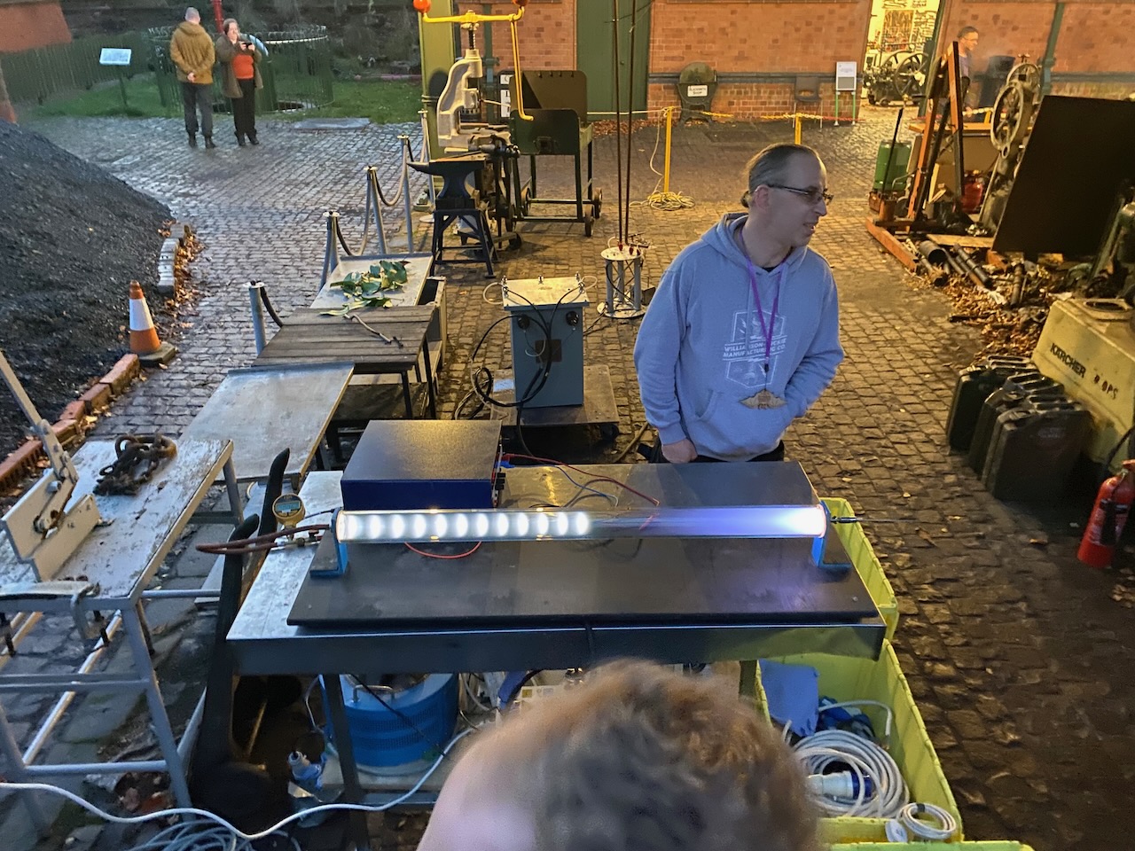
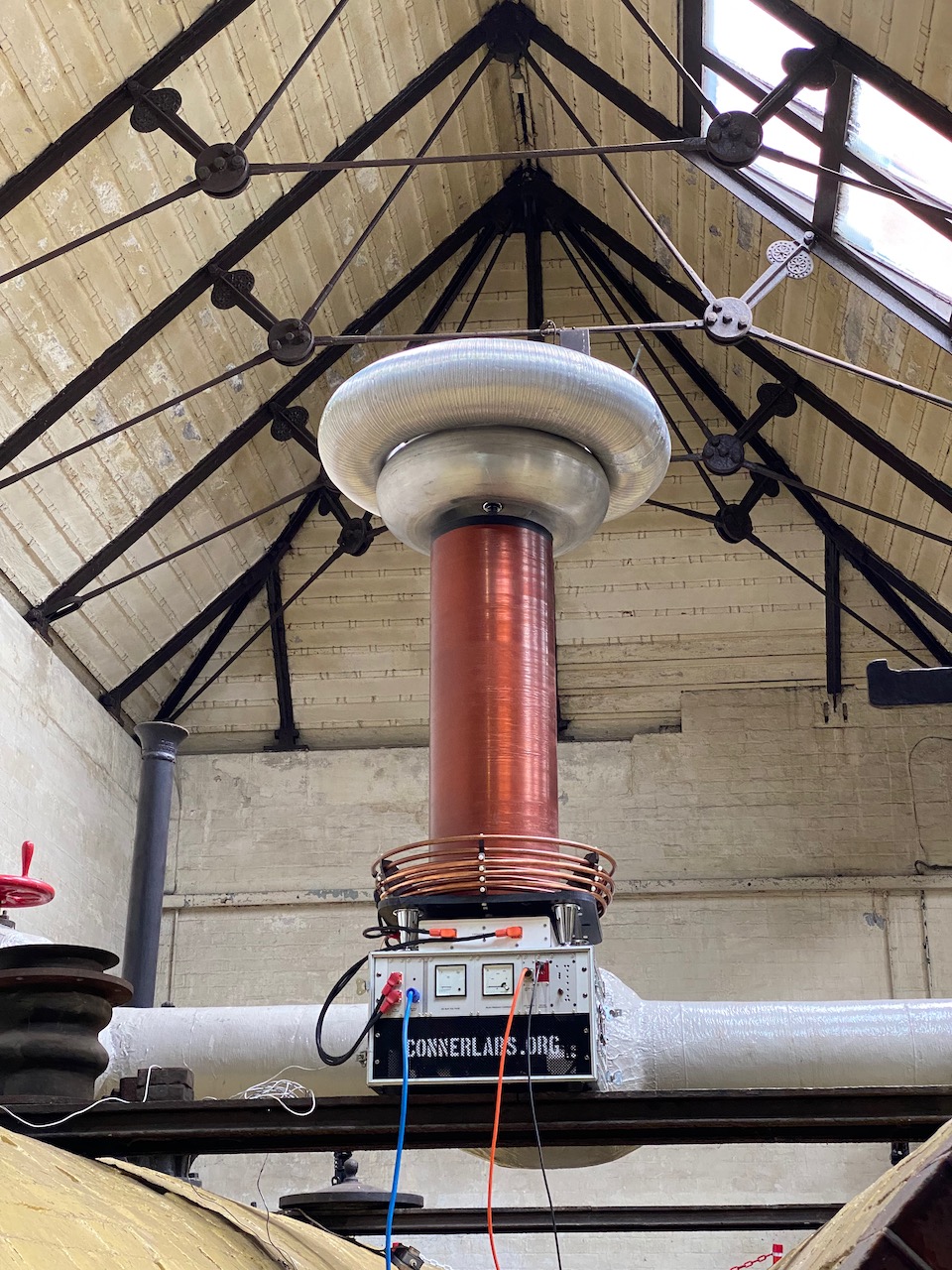
Odin made another appearance at Nottingham Gaussfest 2022. This year I got to run outdoors with a 32A 3 phase supply! A new spark record of 10ft was set, and a new power consumption record of around 15kW.
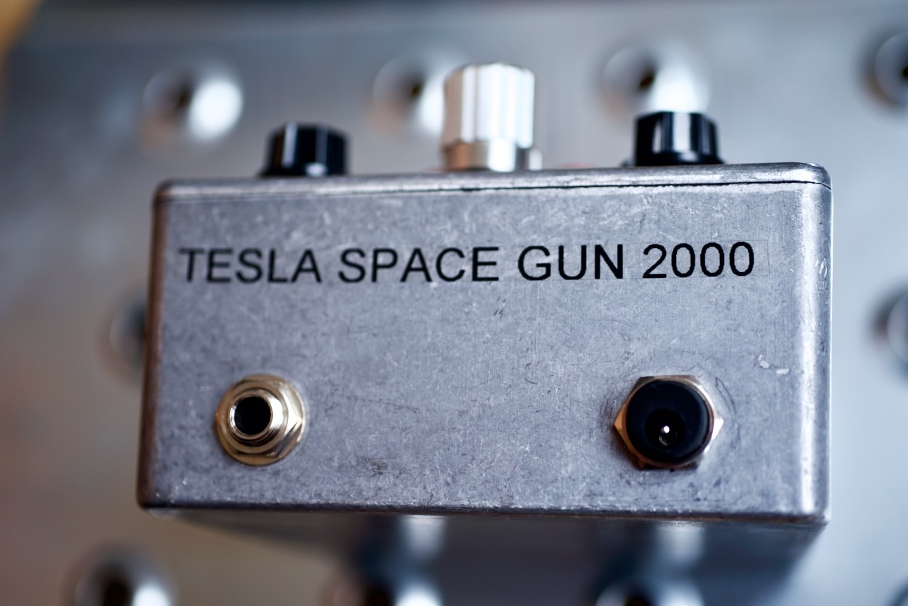
The Tesla Space Gun 2000 dub siren and drum machine were unleashed on an unsuspecting public.
I was so busy setting up and running the coil that I didn’t have a chance to get any photos.
For this year’s Gaussfest I decided to make a dub siren and connect it to Odin.
A dub siren is basically a very simple analog synth used to make sound effects for dub reggae. The original ones were a simple circuit with two 555 timers, but there are all sorts of variations on the theme. I was especially impressed by the Rigsmith GS1, which seems to contain some sort of toy sound effect IC.
I’m sure I had something similar mounted on the handlebars of my Raleigh Chopper in the 80s. How hard could it be to build one?
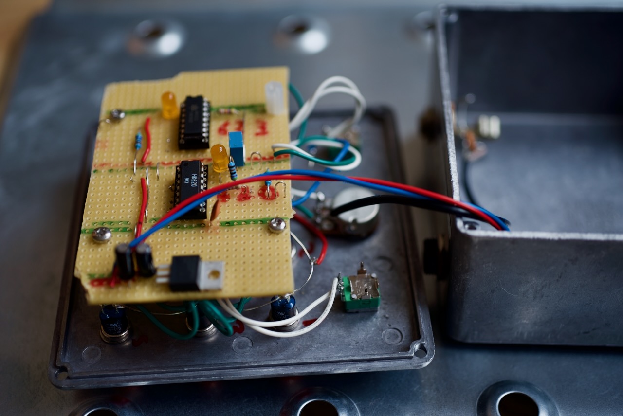
After some Googling and searching eBay, I found a surplus dealer selling some promising looking chips: the HK620 and HK623.
To make my dub siren I copied the data sheet application circuits almost exactly. The only change I made was to replace the timing resistor (“Rosc” in the datasheet) with a 1M pot in series with a 47k fixed resistor. I also added a 3.3 volt regulator so it could run off the standard 9V guitar pedal supply.
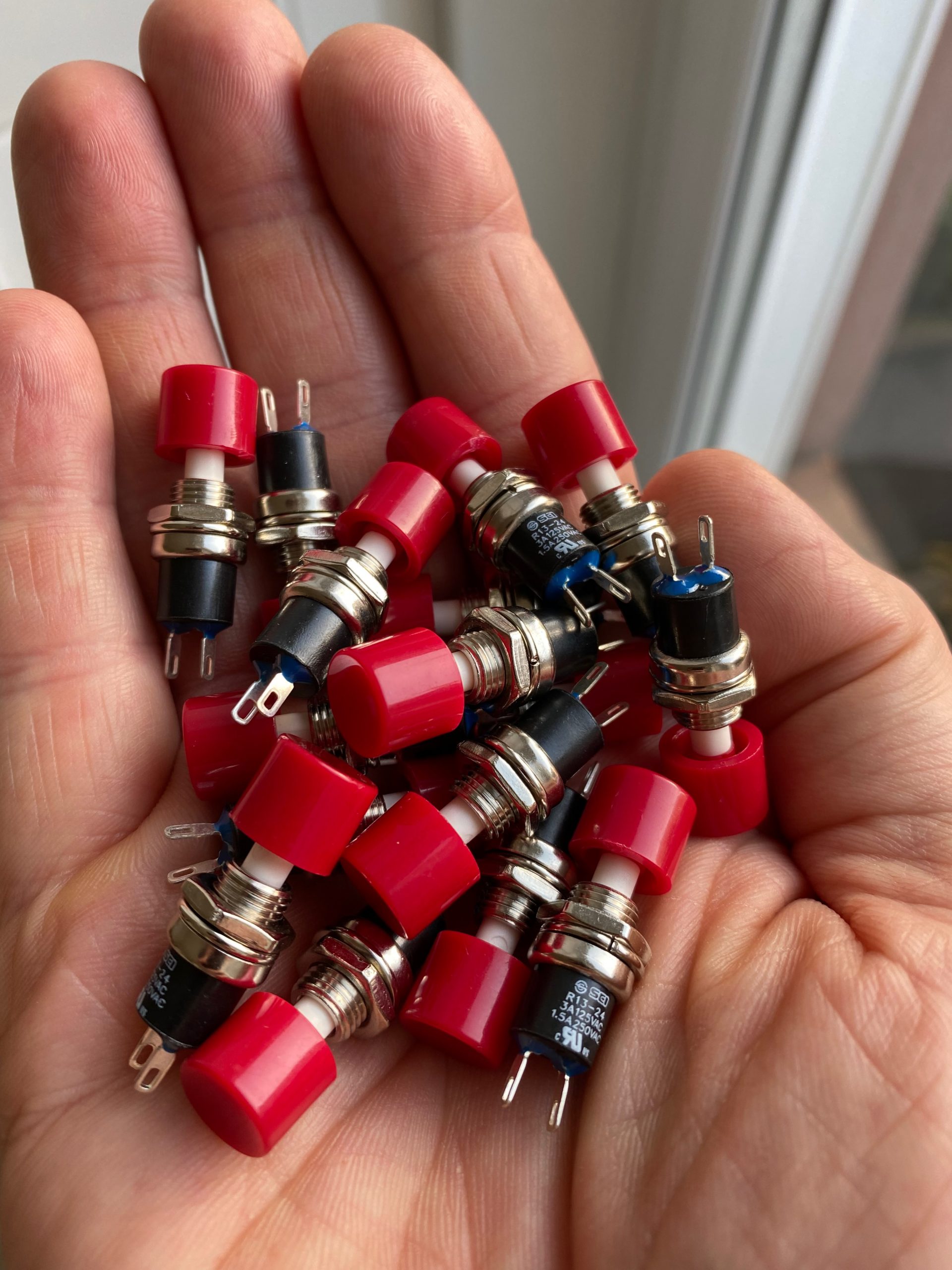
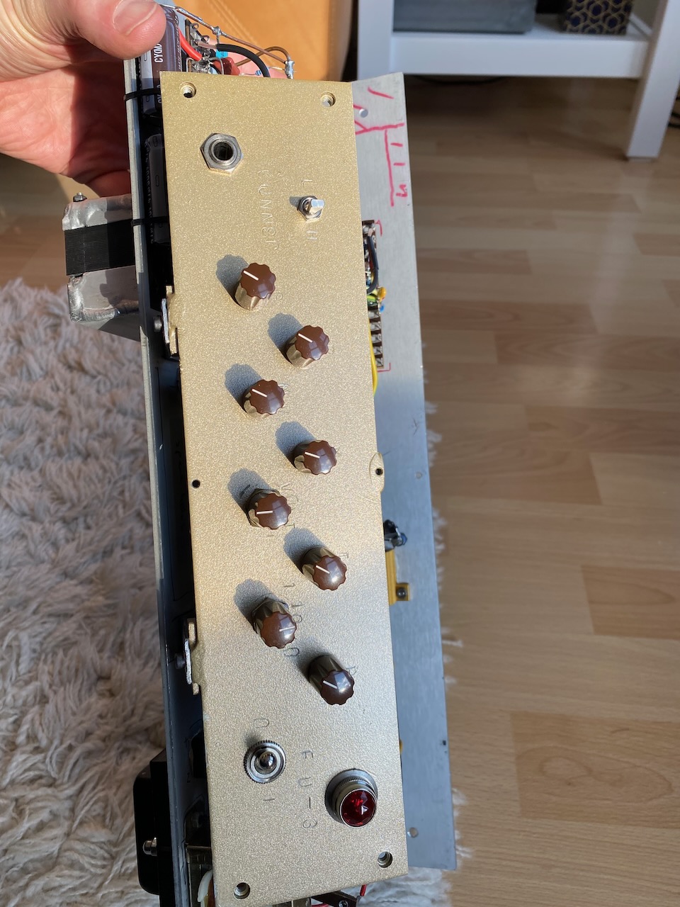
Buttons… So many buttons…And a Hammond diecast box and some other bits and pieces
It sounds identical to the Rigsmith! Have they been shopping at Budgetronics too? 😀
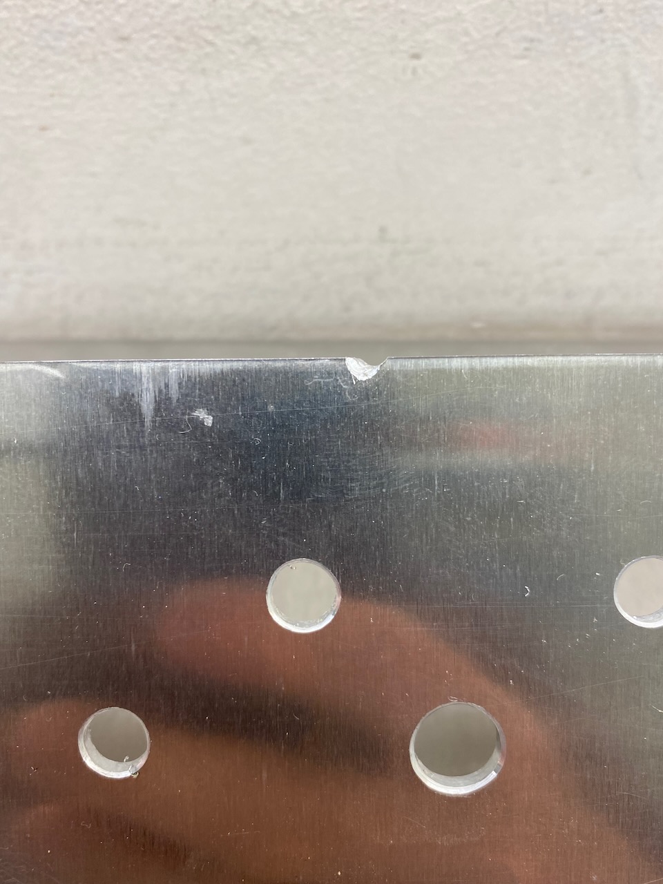
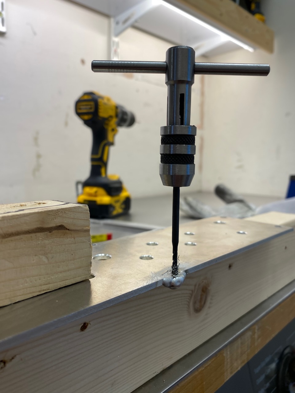
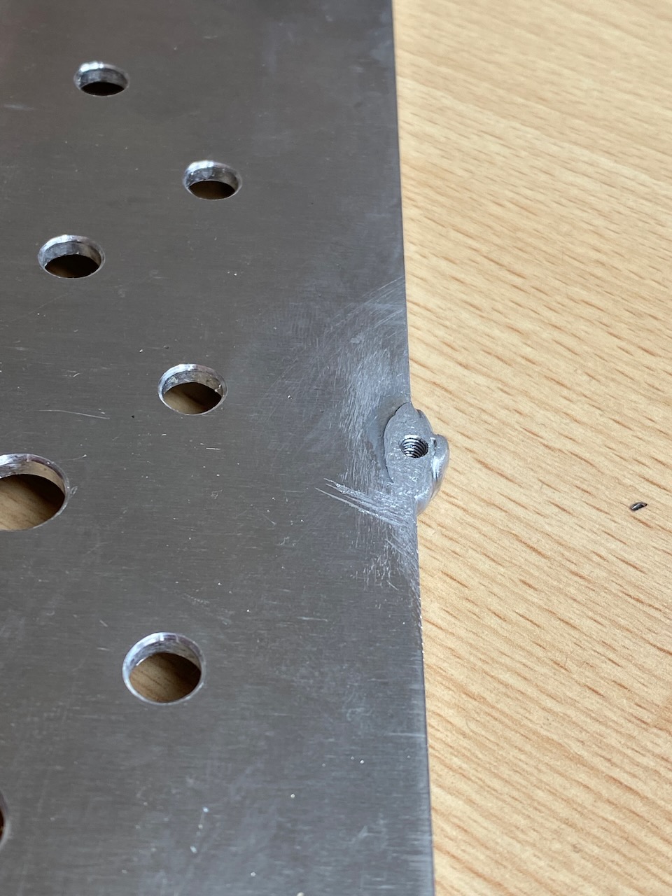
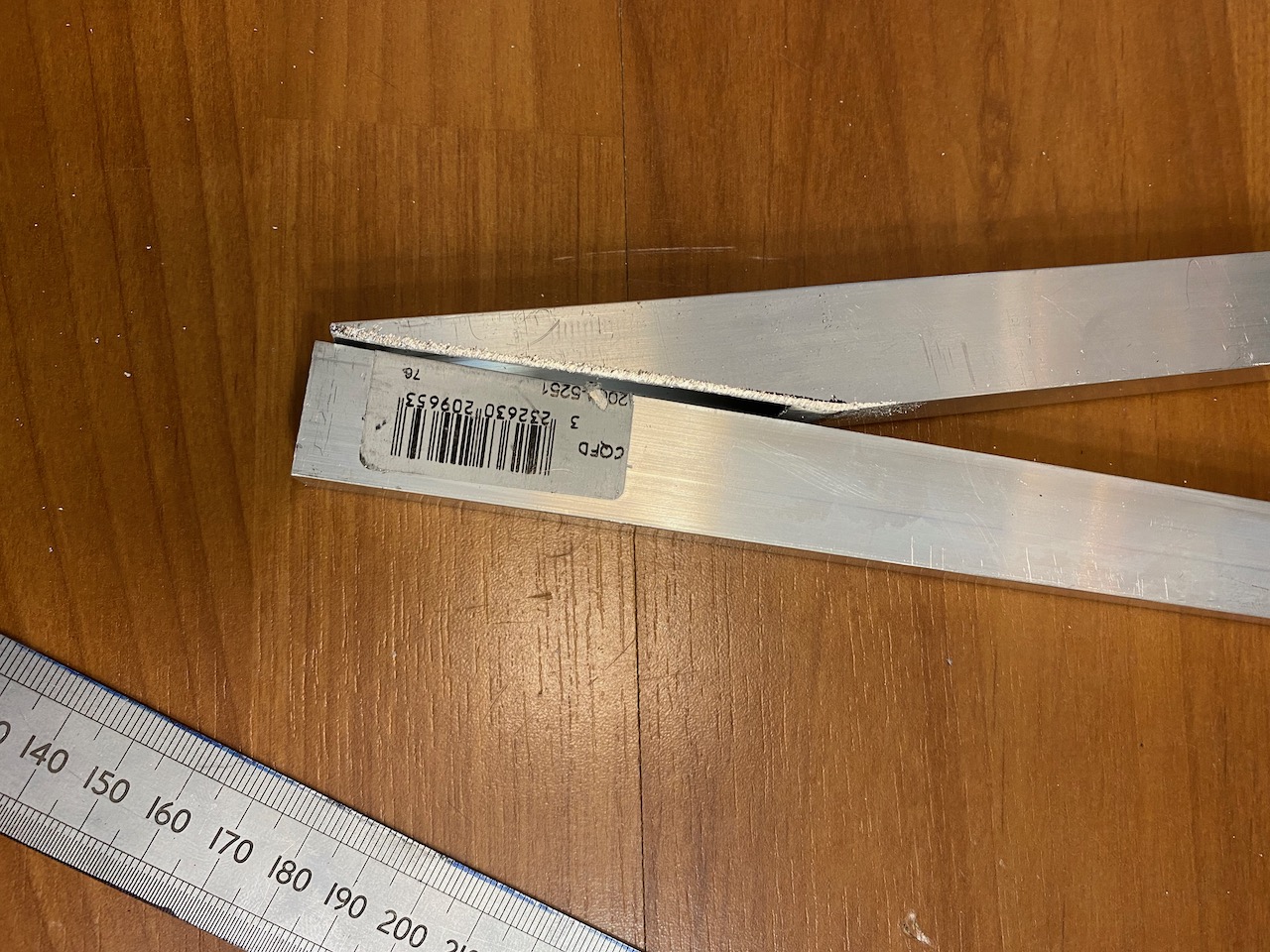
I started with a 3mm piece of aluminium pre-cut to size by Metal Supermarkets. The existing screw holes were easily replicated with PEM nuts, but the old faceplate vibrated horribly, so I wanted to add 2 more mounting bolts, and oh dear, the drilling for the top one just missed the panel.
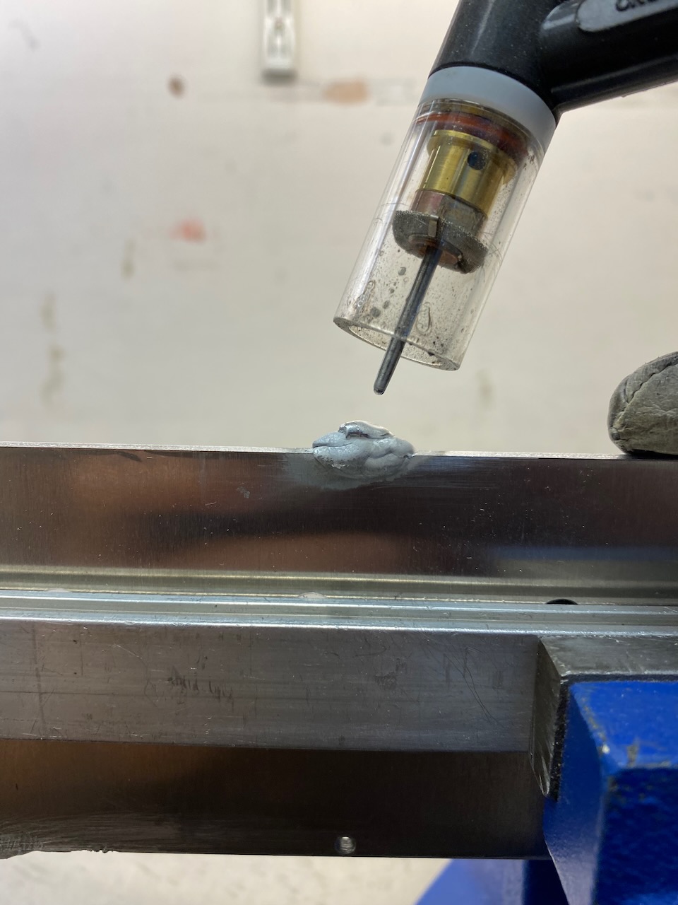
This was a perfect excuse to zap something with the TIG welder.
Zap and tap
With this done, a coat of gold paint and a pasting with letter punches…
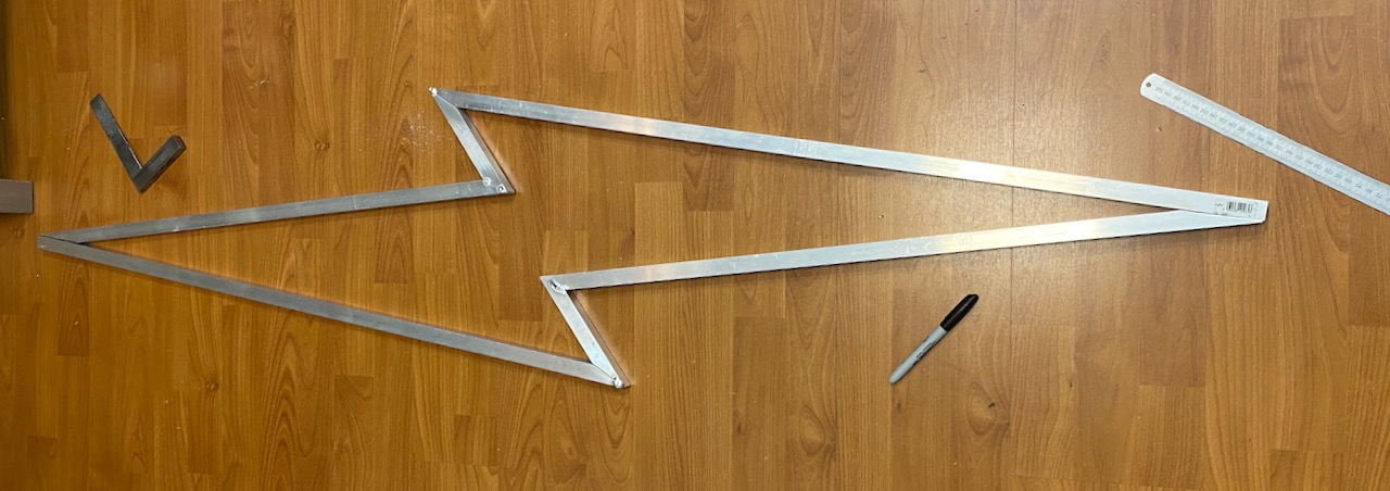
Wanted a track light fitting for the living room and more aluminium welding practice 🙂
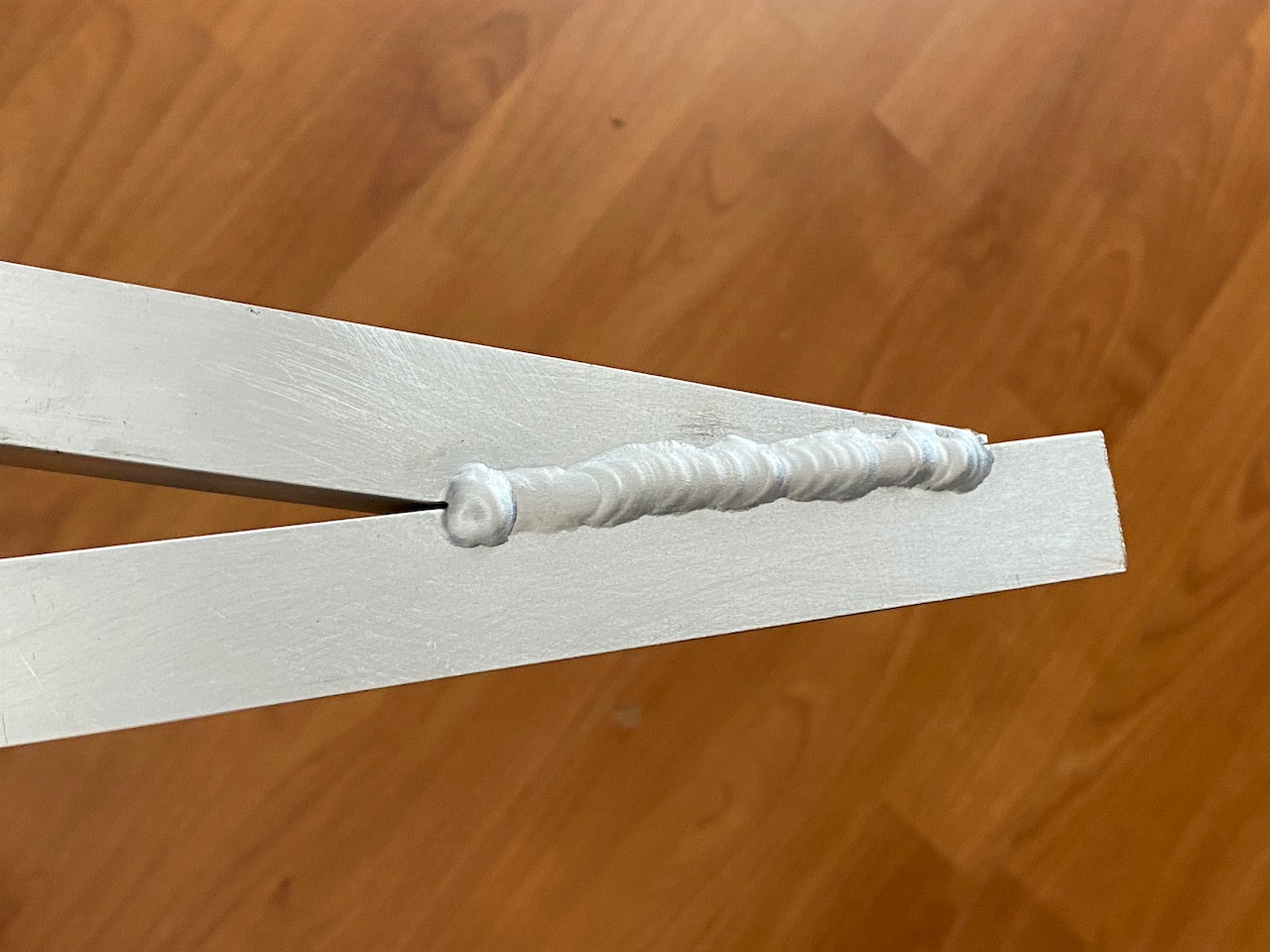
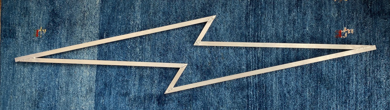
20x20mm square tube (ashamed to admit I bought it from B&Q) was cut into the shape of a lightning bolt.
Oh dear, the mitreing could have been better…
This is the nicest weld, there were much worse 😀 I got off to a bad start by burning several holes in it while trying to tack it together, and had to weld up the holes. I didn’t realise the tubing was only 1.6mm thick and started off with too large a tungsten and too much current. Another reminder to always test the welder settings on a scrap of the material you’re going to use… 🙂
After fully welding (OK I didn’t do the inside corners 🙂 )
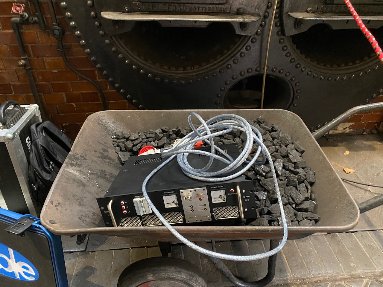
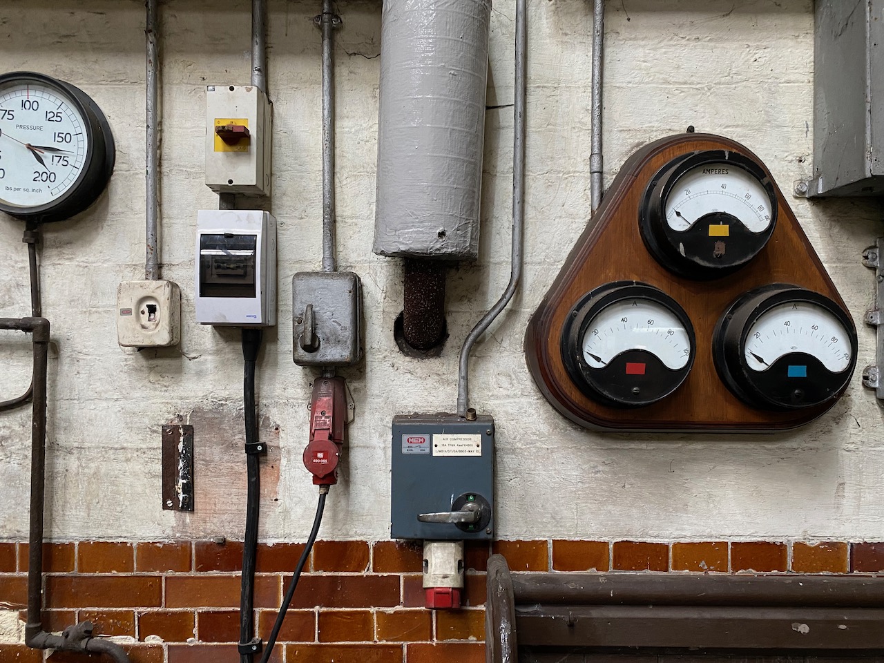
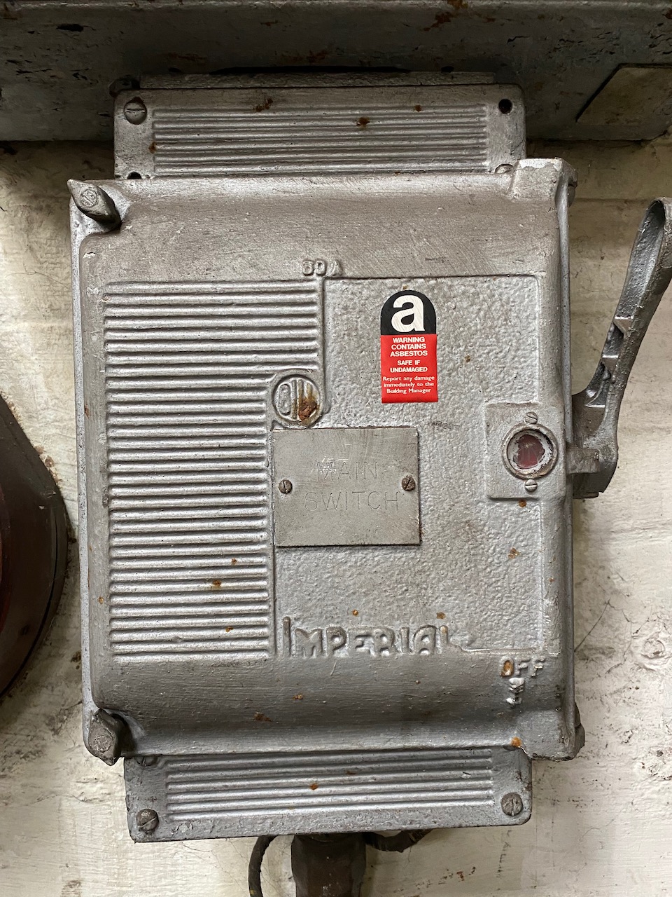
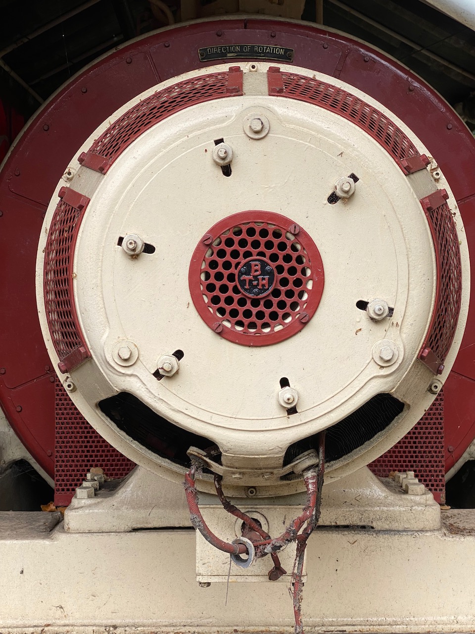
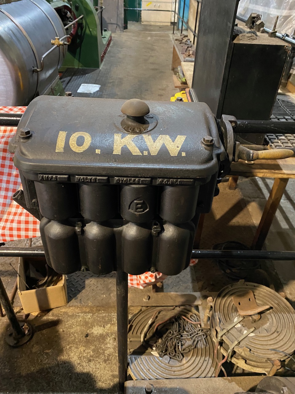
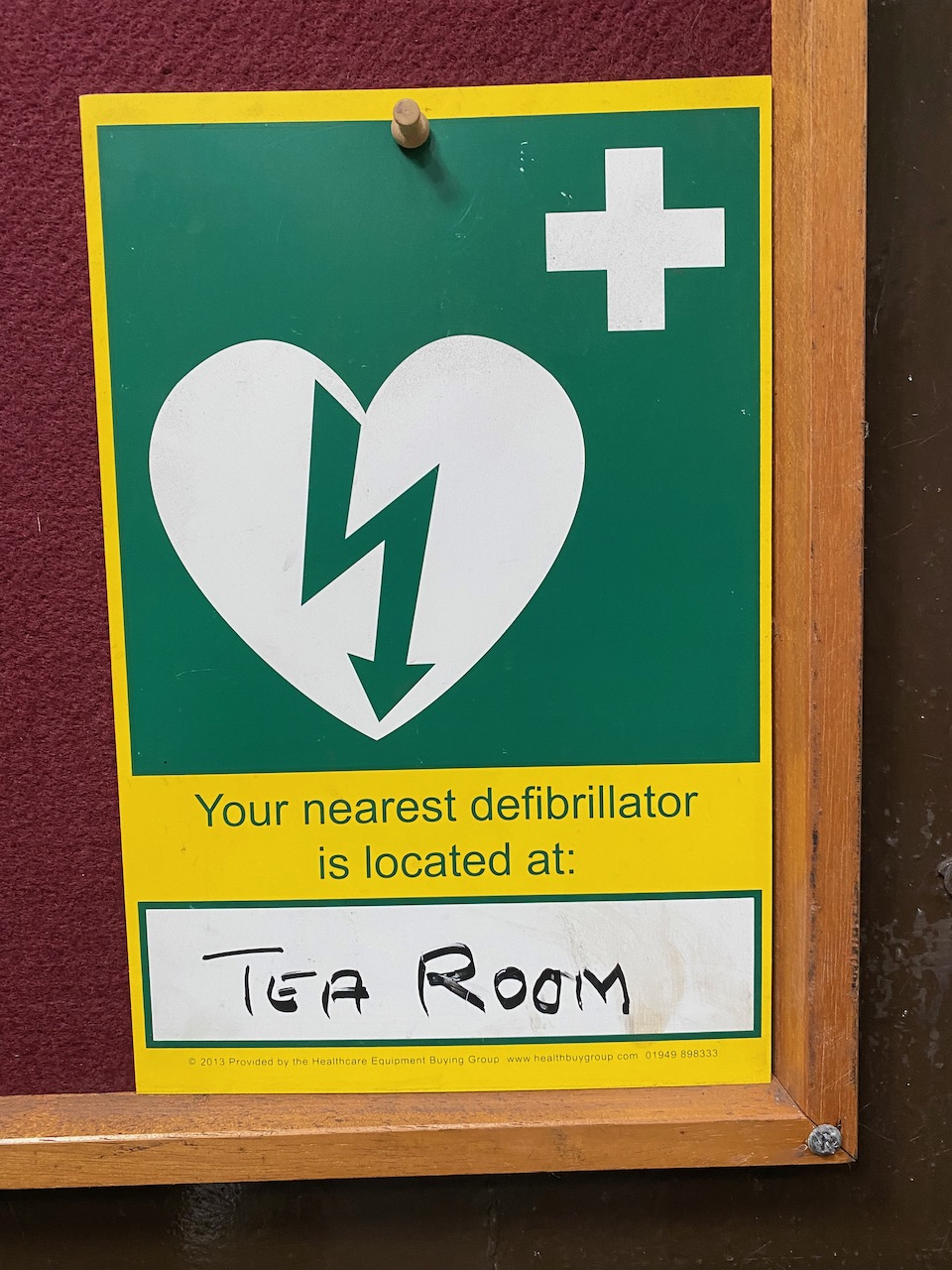
Boiler house switchboard… Yes my setup moved the meters 🙂 Mmmm, asbestosThis generator was a bit too small to power Odin 🙁This one was too bigMy performance did actually use about 10kWAn event like this would not be possible without defibrillators and a tea room.
As you can imagine from the number of acronyms in the title, this took a huge amount of fiddling and was very confusing, so documenting it here for my own benefit and others’. 🙂
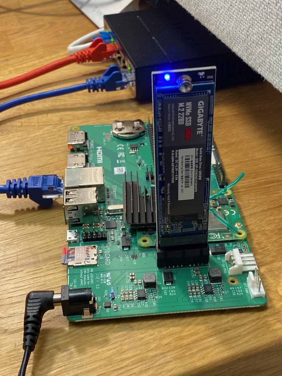
Those blue LEDs >_<
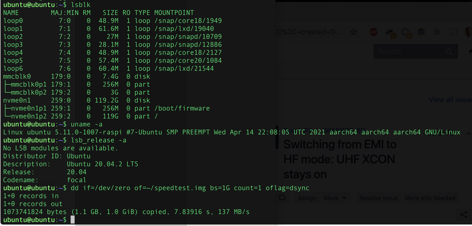
I wanted to run Ubuntu Server ARM64 on a Raspberry Pi CM4 dev board using a NVMe SSD for at least the root filesystem (and ideally booting from it)
Step 1: Update the CM4’s bootloader firmware
The CM4 probably has an older bootloader firmware installed from the factory that doesn’t support NVMe. This step is best done from a Linux PC: I used an old Acer laptop running Zorin 16. The below commands are to be entered in a terminal window:
First you need the latest version of the Raspberry Pi USB boot tool. This has to be built from source, and you may need to install some dependencies first (-1000 geek points if you didn’t already have git and build-essential 🙂 )
Now it’s time to build the USB boot tool from source…
git clone --depth=1 https://github.com/raspberrypi/usbboot
cd usbboot
make
Now you need to edit the boot order settings and get the latest EEPROM image. This part is adapted from this tutorial which doesn’t work verbatim any more (the “nvme” folder doesn’t exist in the usbboot repository, but substituting the “recovery” folder works)
cd recovery
sed -i -e '/^BOOT_ORDER=/ s/=.*$/=0xf25416/' boot.conf
NVMe on Raspberry Pi is still kind of bleeding edge, so it’s best to use the newest versions of everything. pieeprom-2021-07-06.bin was still the latest image at the time of writing:
Note: At this point the update script crashed complaining that it couldn’t find Python. I guess Zorin 16 removed Python 2.x and forgot to make Python 3 the default? The python-is-python3 package fixed that for me. Hopefully your Linux distro has a functioning “python” already, in which case don’t execute this command, it’ll probably break something!
sudo apt install python-is-python3
Finally it’s time to burn your changes to the CM4… The “disable eMMC Boot” jumper must be fitted on J2 for this to work (Unless you have a CM4 Lite I guess…)
cd ..
sudo ./rpiboot -d recovery
Now connect the CM4 Dev board J11 “USB Slave” to a USB port of your Linux PC and apply power to the 12V DC input.
The rpiboot tool should boot up the CM4 over USB and flash the new EEPROM image and boot order settings. Once the command line spew stops and the power LED on the dev board starts to blink rapidly, the process is complete and you can disconnect power.
Step 2: Try to boot from NVMe, fail
At this point I already had an ARM64 Ubuntu 20.04 LTS image downloaded from here and uncompressed to my Gigabyte GP-GSM2NE3128GNTD SSD. So I removed the SD card from my CM4 dev board and tried to boot from the NVMe.
I got a surprisingly informative error message from the Raspberry Pi bootloader (on a monitor connected to HDMI0)
start4.elf is not compatible. nvme boot requires newer software
So my first attempt at a fix was to update a 32-bit Raspbian SD card image with rpi-update and then copy the start4.elf and fixup4.dat files from that image to the NVMe boot partition. This got me to the next problem: The Ubuntu 20.04 image uses a version of U-Boot that doesn’t support NVMe, so it just sticks waiting for a boot device.
Next I tried downloading the Ubuntu Server 21.04 image and burning it to a SD card. I planned to go through the full process documented in the forum thread, starting with upgrading the Ubuntu image, so I inserted the SD card and powered up.
Step 3: Unexpected success
Imagine my surprise when it booted into Ubuntu 20.04 from the NVMe instead of 21.04 from the SD card as I was expecting. 😀
I guess what must have happened is that the boot partition on the 21.04 SD card had a version of UBoot that recognised the NVMe and treated it as a higher priority than the SD.
Confirming that the SD card is unused and root filesystem is on the NVMe SSD. It’s fast 8)
The next gambit would be to copy the boot partition from the SD card to the NVMe and see if it can boot directly from NVMe. But it works well enough as is, I don’t want to break it! This is left as an exercise for the reader 😉
Step 5: Try to make it boot directly from NVMe
Unfortunately on subsequent boots it flipflopped between NVMe and SD card as the root partition. So I thought since it’s Friday afternoon I should try to get it to boot directly from NVMe.
I started by deleting all files in the boot partition on the NVMe and replacing with the ones from the Ubuntu 21.04 SD card. The kernel is in /boot/vmlinuz, while the modules are stored on the root filesystem, so this would normally cause the modules to fail to load, except I noticed that I somehow managed to update the Ubuntu 20.04 installation on the NVMe so it was running the same kernel and modules as 21.04.
This still didn’t work, so I went back to that forum thread and replaced start4.elf and fixup4.dat with the ones from the updated Raspbian image.
Finally I got a direct boot from NVMe, with what I guess is Ubuntu 21.04 kernel and 20.04 userland. That works fine for me, I’d rather it ran a LTS version of Ubuntu.
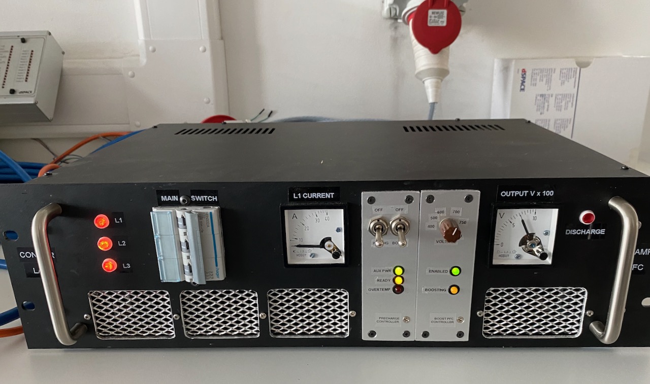
We plugged it into the 3 phase outlet and it started up normally! 😀
When smashed with 750V the Tesla cabin heater would draw an impressive amount of power while warming up. Unfortunately the steady state power draw was only about 2kW, probably something to do with the rather weak fan cooling it.
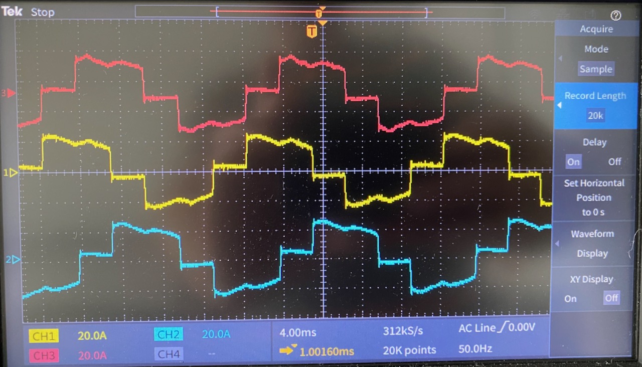
The PFC line current waveforms at (roughly) this 11kW output power level. No surprises here, they look exactly like the theoretical ones for this circuit. (Except strictly speaking the red one is upside down 🙂 ) The theoretical power factor for this waveform is 0.95.
We don’t have a 3 phase power analyser in the lab, so I used 2 single phase ones on the input, according to the old “2 wattmeter method“. To be honest this didn’t work very well, as the power drawn by the PTC heater was always changing, and it was impossible to make sure the 2 meter readings corresponded to exactly the same time. Also, the PF reading is rubbish due to the inherent 30 degree phase shift: to get the actual PF you have to plug the wattage readings into a complicated formula.
When the heater reached steady state, I measured an input power of 2000W, an output of 1900W, and a power factor of 0.96. From an academic point of view it would have been nice to measure the efficiency at higher powers, I expect that 100W is mostly switching losses and the efficiency will increase with heavier loads.
The main goal was to get confidence that the PFC would work at its first gig, and this has been achieved 🙂
Another problem I have with the cabin heater testing (And the PFC testing 🙂 ) is that the PFC is not designed to start up into a load. This isn’t a problem for the intended application, as the Tesla coil won’t draw any current until it’s commanded to. But to power a resistive load, I have to use a switch to connect the load after the PFC has started up.
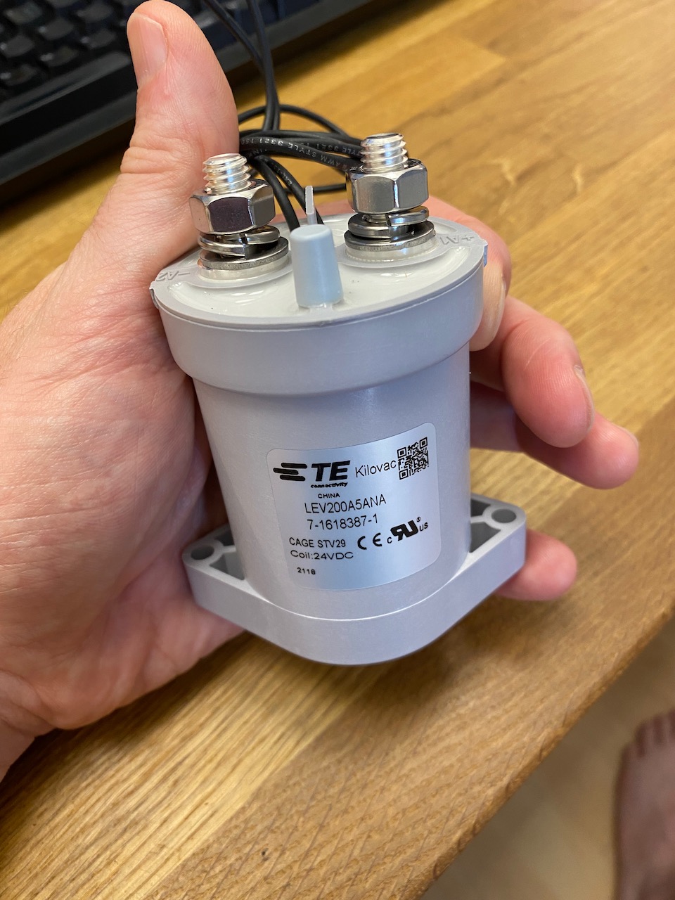
For the previous immersion heater tests I used an ordinary 240V AC rated switch. This will make a DC circuit, but won’t break it: the arc simply won’t go out until the entire switch is incinerated. Of course if you’re reading this there’s a fair chance that you actually enjoy burning things to a crisp with electric arcs, but I have to be on my best behaviour to get the keys to the 3 phase outlet at work, and proper DC rated contactors are getting cheaper anyway thanks to the proliferation of electric vehicles.
The Kilovac LEV200 has hydrogen filling and a permanent magnet to blow out the arc. It’s good for several hundred amps at 900V DC.
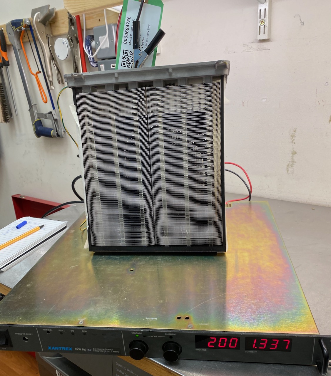
I thought I’d better test the characteristics of the PTC elements in a scientific manner as opposed to just applying 750V DC from the PFC and seeing what happens.
When measured with a multimeter at room temperature, each element read about 600 ohms. This would imply a rather low power output if that was the minimum resistance.
For my next experiment I connected one of the elements to my old Xantrex 600V bench power supply. The 600 ohm cold resistance would imply a draw of no more than 1A at 600V if the element was purely PTC. But to my surprise, the current draw actually began to increase as the element got hotter, eventually hitting the PSU’s 1.7A current limit at only 200V.
This means that the elements must actually start off as NTC, and transition to PTC at a higher temperature. That kind of makes sense, as a car heater matrix has to be able to start up from very low temperatures. Purely PTC elements would presumably exhibit an immense current surge when the heater is turned on after leaving the car parked overnight in Canada. 🙂
I was wondering why Tesla bothered to implement individual control of the 6 elements, and I guess the turn-on surge is the answer to this too: by turning them on sequentially the surge can be made 6x smaller. It’s not like a Tesla traction battery (or even an IGBT) would care if the turn-on surge was 10A or 60, but maybe it allows them to use a lower rated fuse to connect the heater to the battery. Fuses rated for high voltage DC are expensive so the savings made here might outweigh the cost of 5 IGBTs and drivers.
Anyway, I couldn’t test above 200V due to the limited output current. The next larger PSU I have is the PFC, and it has a minimum output voltage of 400V (600 on 3 phase) so I will just have to “send it” as the kids say nowadays.
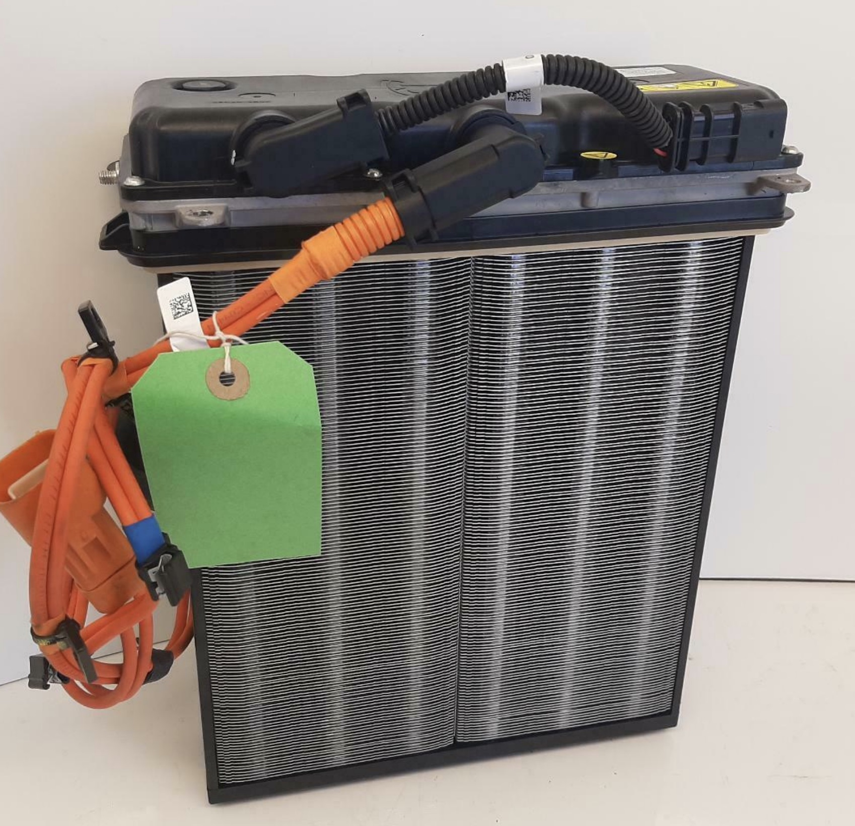
I needed a high power dummy load that was a bit more health and safety friendly than my bucket of immersion heaters. I investigated lots of possibilities until I eventually found a Tesla Model 3 heater matrix on eBay. The Internet said it could draw up to 6kW, and being PTC, it shouldn’t catch fire if I forget to turn the fan on, which would look great on a risk assessment. So I went for it. 🙂
The lid is held on by penta-lobe screws with a tamper-proof peg in the middle. There was nothing in my collection of tamper-proof bits that would fit, but a sturdy flat-bladed screwdriver worked quite well after Dremeling a new slot or just jamming it in hard enough to break off the peg. 😀
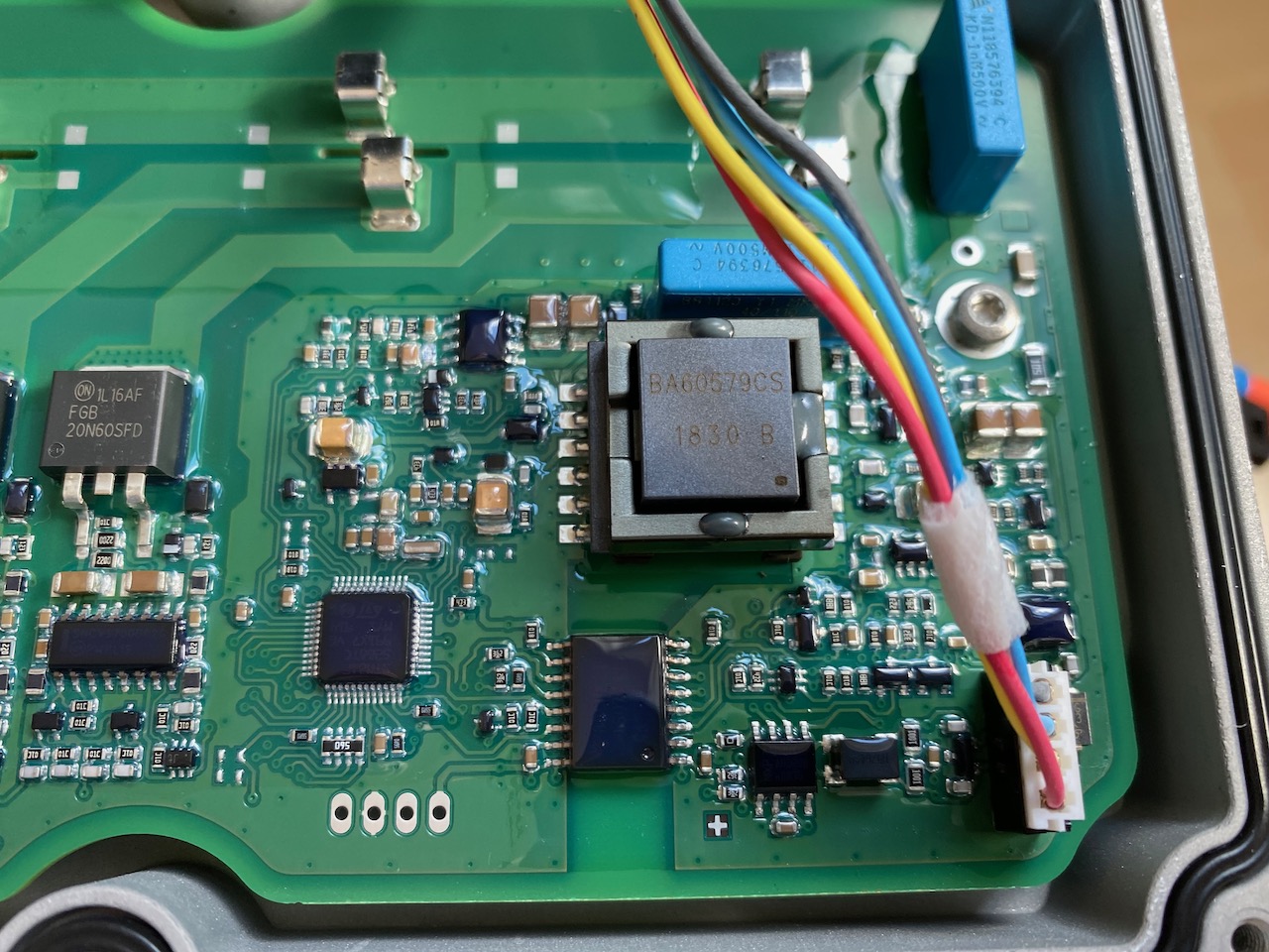
Ooh, fancy! What does all this stuff even do?
There appear to be 6 separate PTC elements, each with low side switching by a 600V IGBT and non-isolated gate driver.
To the left of the IGBTs is a voltage divider and low side current shunt, and on the right an isolated CAN interface and DC-DC converter. Handling CAN communications and A/D conversion of the voltage and current signals, we have an 8 bit ST microcontroller (probably sharing its 0V rail with DC bus negative)
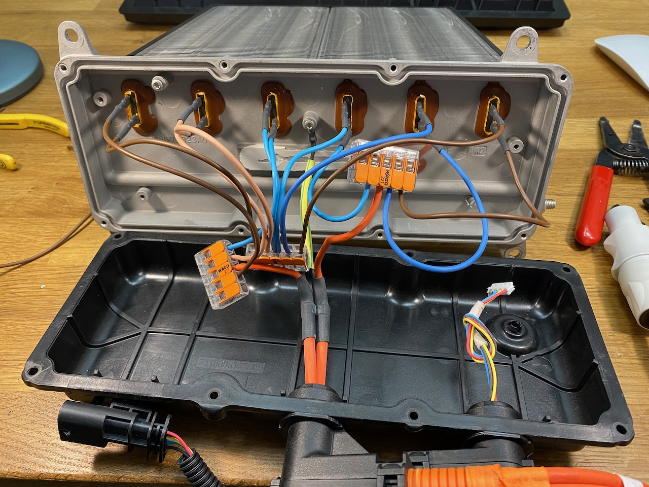
Of course I immediately set to work reverse engineering the CAN protocol so I could command it to connect its elements in 2 groups of 3 for 800V input. Oh wait that’s not gonna work 🙁 we need a hardware solution…
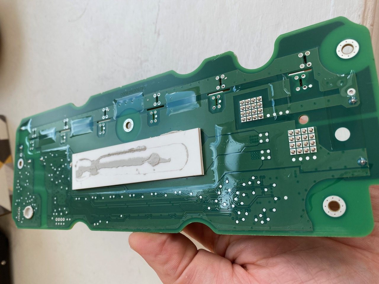
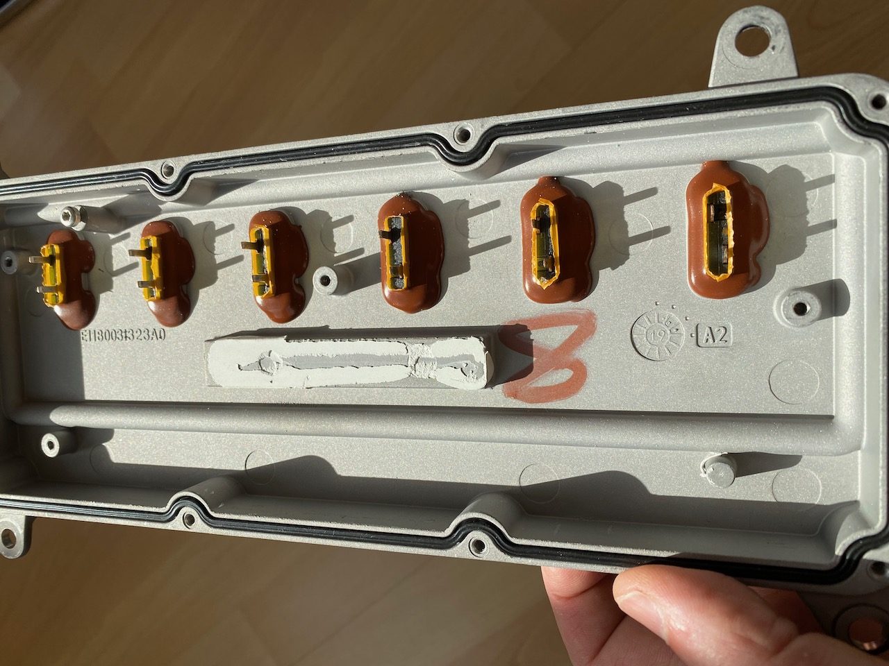
The heating elements were connected to the PCB by spring clips that released quite easily, but the PCB was stuck firmly to the aluminium enclosure with thermally conductive glue. I freed it with the old embedded programming trick of heating the enclosure with a heat gun and prying with a paint scraper. (sadly this doesn’t work any more in Python 3 😉 )
With the PCB removed we can see the terminals for the heating elements, looks as if some sort of spade terminal should fit nicely. (Also note the little nodule at bottom right which appears to be for cooling the CAN transceiver chip.)
And after a pulsating second half the score is Wago 221, CANbus 0. 😀


