In the previous post I mentioned that I couldn’t drive the MOSFETs directly from the controller chip because they need a negative voltage to turn off. The easiest way to provide this was with an isolated gate driver using the excellent Silicon Labs Si8271 IC.
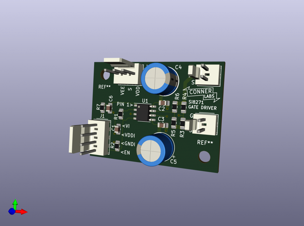
Due to the tiny size of this IC and the requirement for a very tight layout to minimise stray inductance, I designed a PCB for it. This was also an excuse to finally start learning Kicad after years of using Eagle.
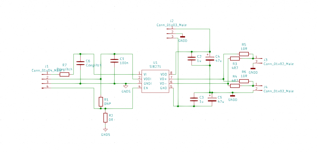
Power is supplied by a Murata MGJ6 DC-DC converter connected to J2. +15V to pin 1 and -5V to pin 2. The same DC-DC converter powers the opamp on the voltage feedback isolator board.
R7 is a small value like 22 ohms. I installed a 10k resistor in place of C6 to pull down the input if it became disconnected. R2 was not fitted and R1 was a 0 ohm link, the opposite of the schematic (I got the enable pin logic the wrong way round)
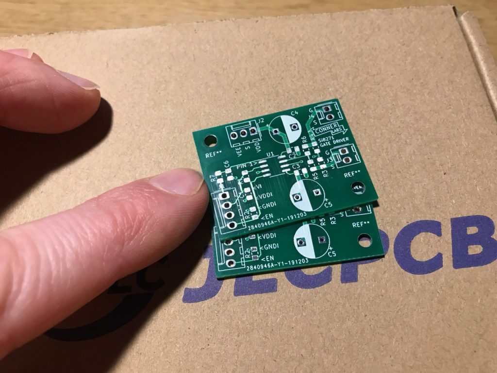
I uploaded the Gerber files to JLC– a Chinese manufacturer based in Shenzhen who ship worldwide- and had the boards the following week for a cost of about £5. JLC are 1/10 the cost of any UK PCB house and have really lowered the barrier to entry for hobbyists.
Leave a Reply