Fixing EMF carnage part 2

With the PFC sorted I turned my attention to the main coil unit. I started by replacing the melted tank capacitors. One had exploded, one looked a bit burnt, and the leg of a third capacitor came off in my hand.
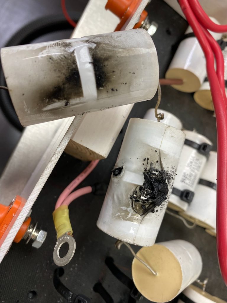
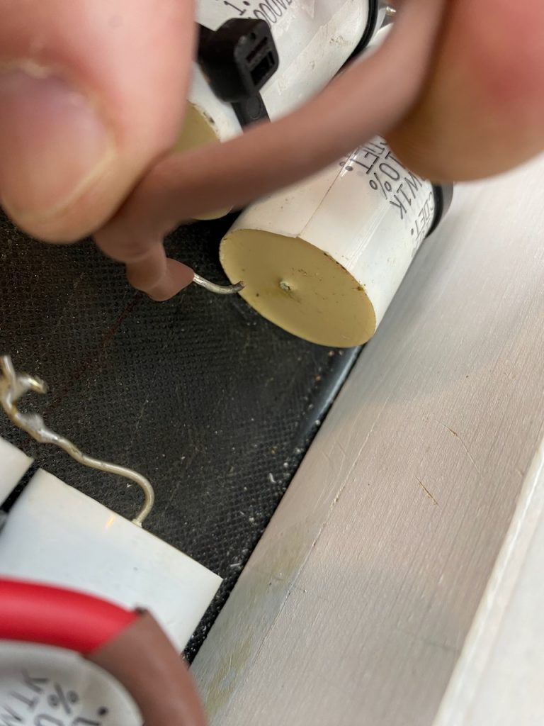
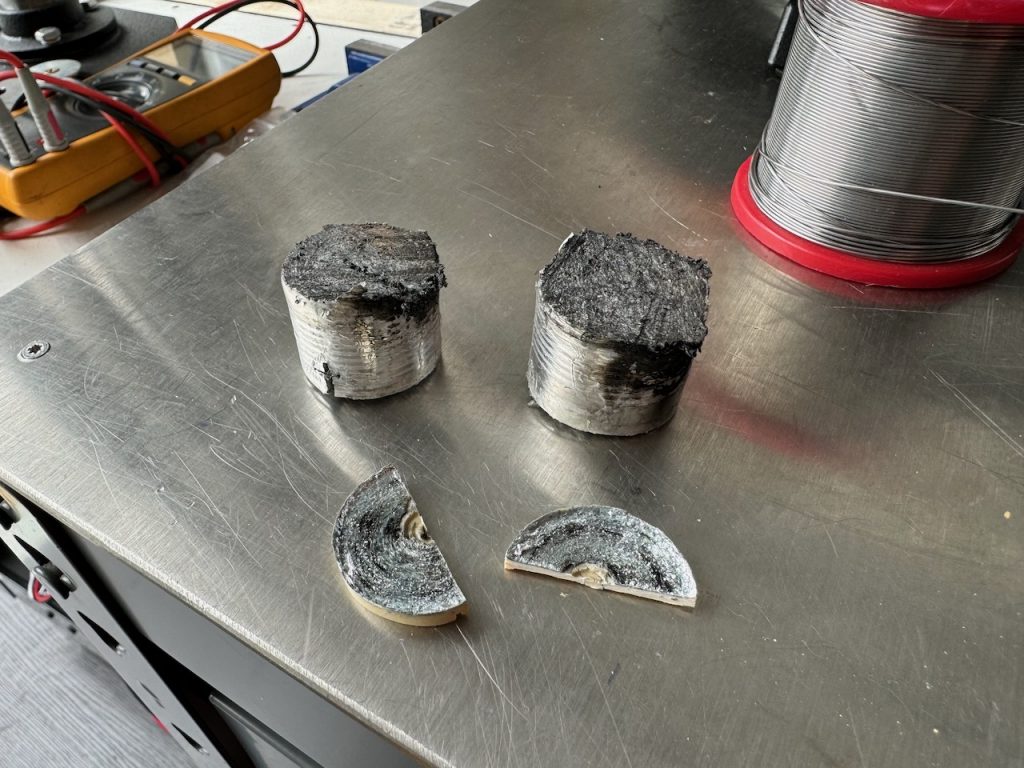
Out of curiosity I cut open the exploded capacitor. The whole inside was just a blackened mess.
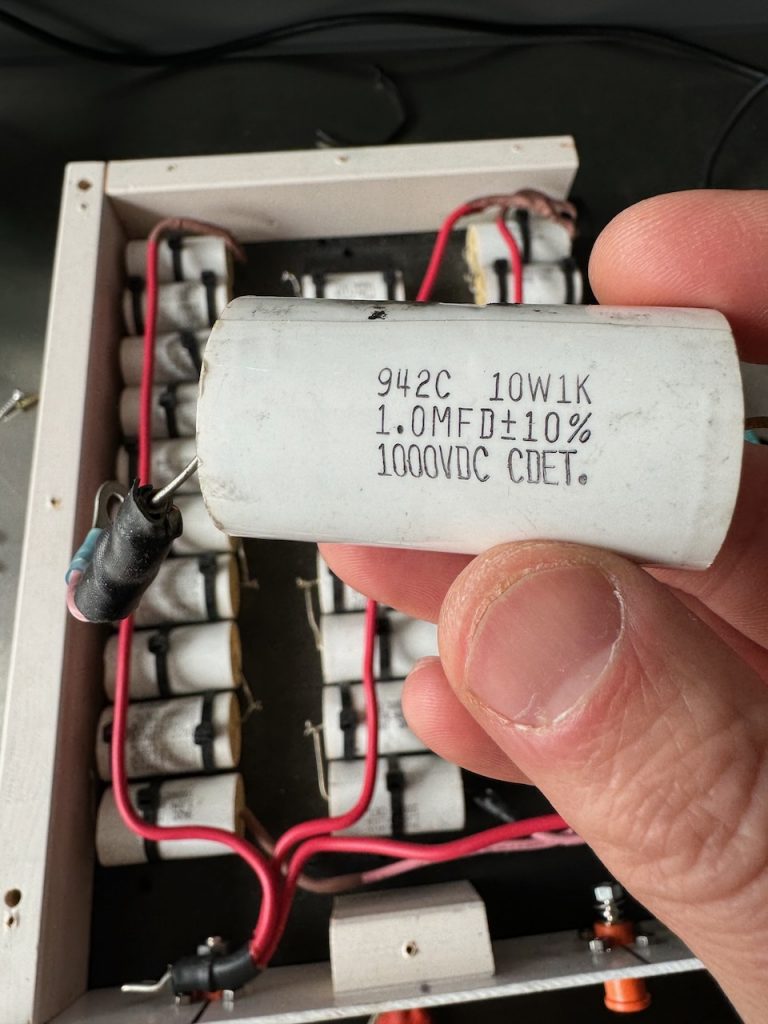
I bought a load of these Cornell Dubilier 942C series capacitors, 1uF 1000V, years ago for the OLTC 2. In Odin they are overloaded to about 3x their rated RMS current and crammed into an unventilated wooden box, so I’m not entirely surprised they failed.
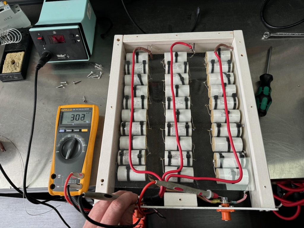
What did surprise me was that every other capacitor tested fine! I found replacements for the destroyed caps in my pile of Tesla junk and the capacitor bank was ready to go again!

Inspecting the rest of the circuitry, the only other problem I could find was a shattered transistor on one of the gate drive boards, which looked like it had been mechanically damaged while taking the unit apart.
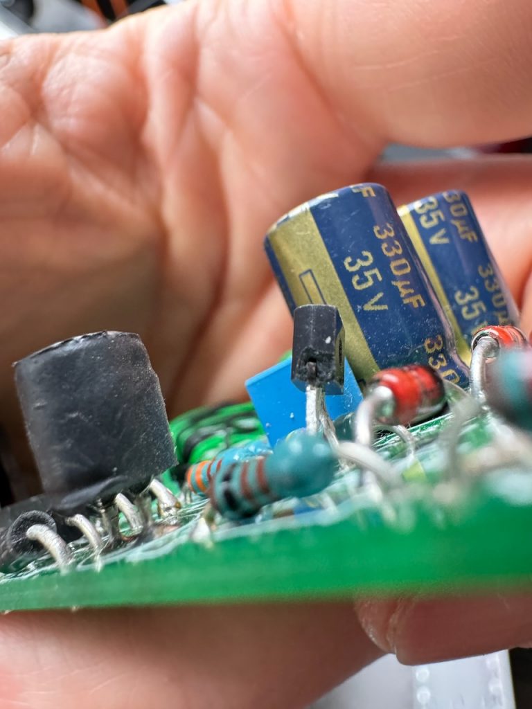
After a few days’ wait for Farnell to deliver a replacement, I headed to the container and set up all the parts of Odin minus the secondary coil for a dummy load test.
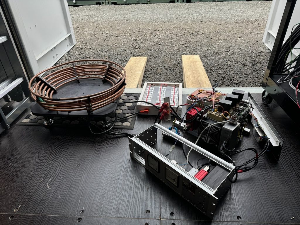
Unfortunately something wasn’t right, the primary current was well below what it should be, and the “Power Fail” LED lit up every time the fire button was pressed.
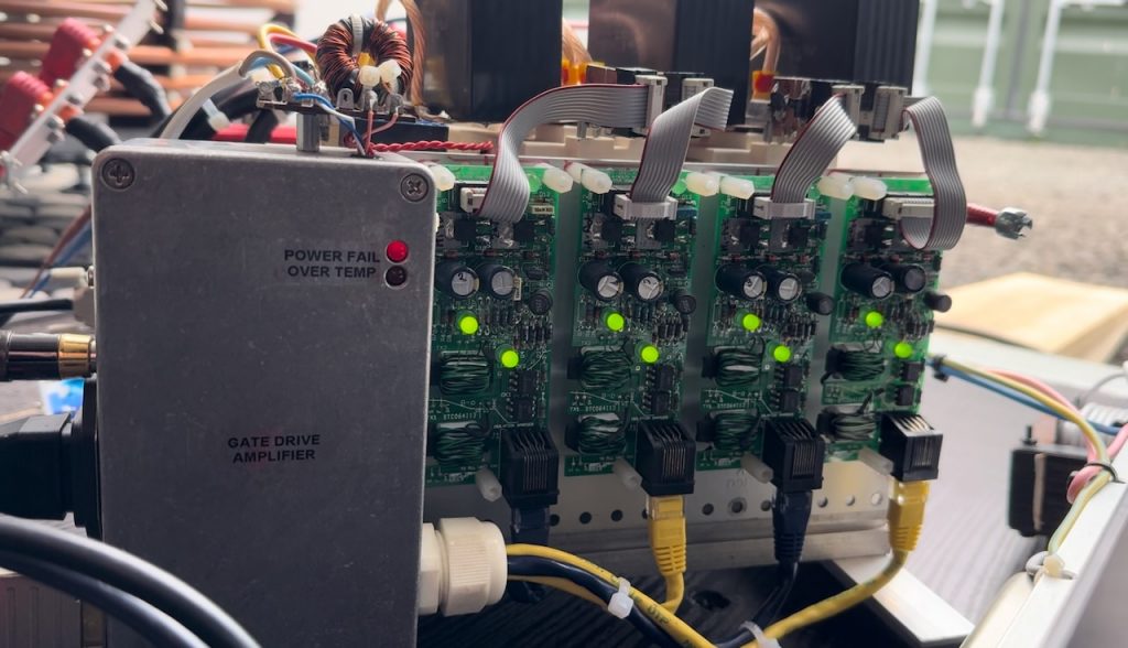
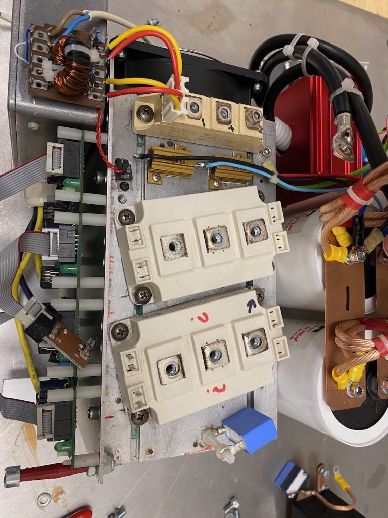
Suspecting a wounded IGBT brick that was drawing a lot of gate current and overloading its gate driver, I took the bridge apart and tested everything, but the IGBTs seemed fine! All the resistance and diode tests checked out, and a 9v battery turned them on and off happily.
Using Banggood’s finest thermal imaging camera (80 x 60 pixels resolution!) I could see that something on one of the gate drive boards was getting exceptionally hot.
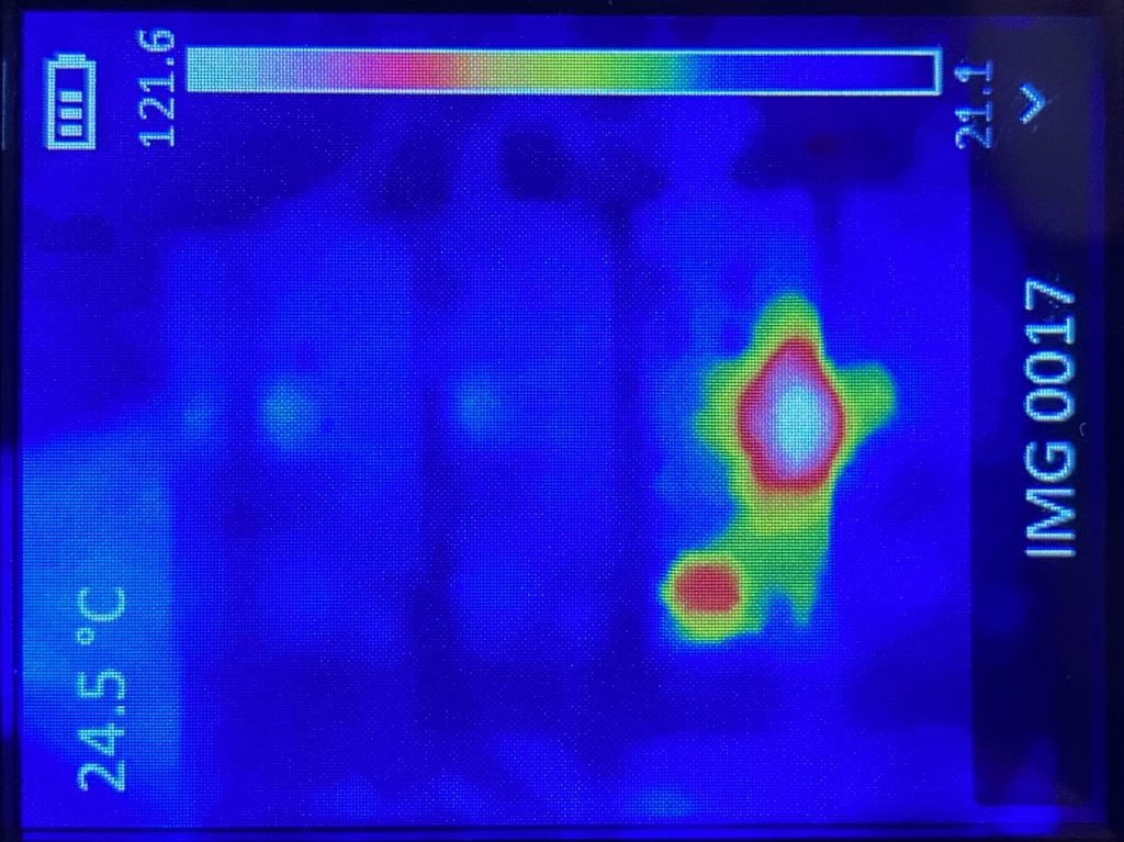
It turned out to be a shorted diode in the gate drive board’s power supply that was causing the voltage to sag horribly and trigger the undervoltage lockout. UVLO is really important in this application where we are driving IGBTs well over their rated current. Trying to pass the full current with insufficient gate voltage will result in a big bang. Luckily the UVLO did its job today and there was no bang.

With the diode replaced, the Power Fail light went out and the gate waveform looked “just perfect” as Allen Millyard would say.
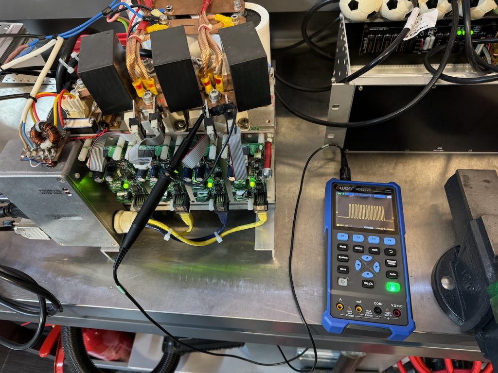
This looked encouraging so I put some DC bus voltage to it and the full 1250 amps of primary current were achieved with no obvious issues.

(These posts are a bit behind of events, I’ve since taken Odin to Gaussfest 2024 and everything performed fine.)

Fixing EMF carnage part 1

During Odin’s final performance at EMF there was a loud bang and everything stopped working. I decided it wasn’t worth attempting a field repair as there were basically only 20 minutes of the festival left and most of the potential spectators were heading home.

Reviewing some video of the fatal performance, I could see a blue light shining out of the PFC after which Odin’s spark output rapidly declined to nothing. This implied that the coil was still working after the PFC died, and might actually be undamaged, apart from the melted tank capacitor that I later replaced with Dawncaps.

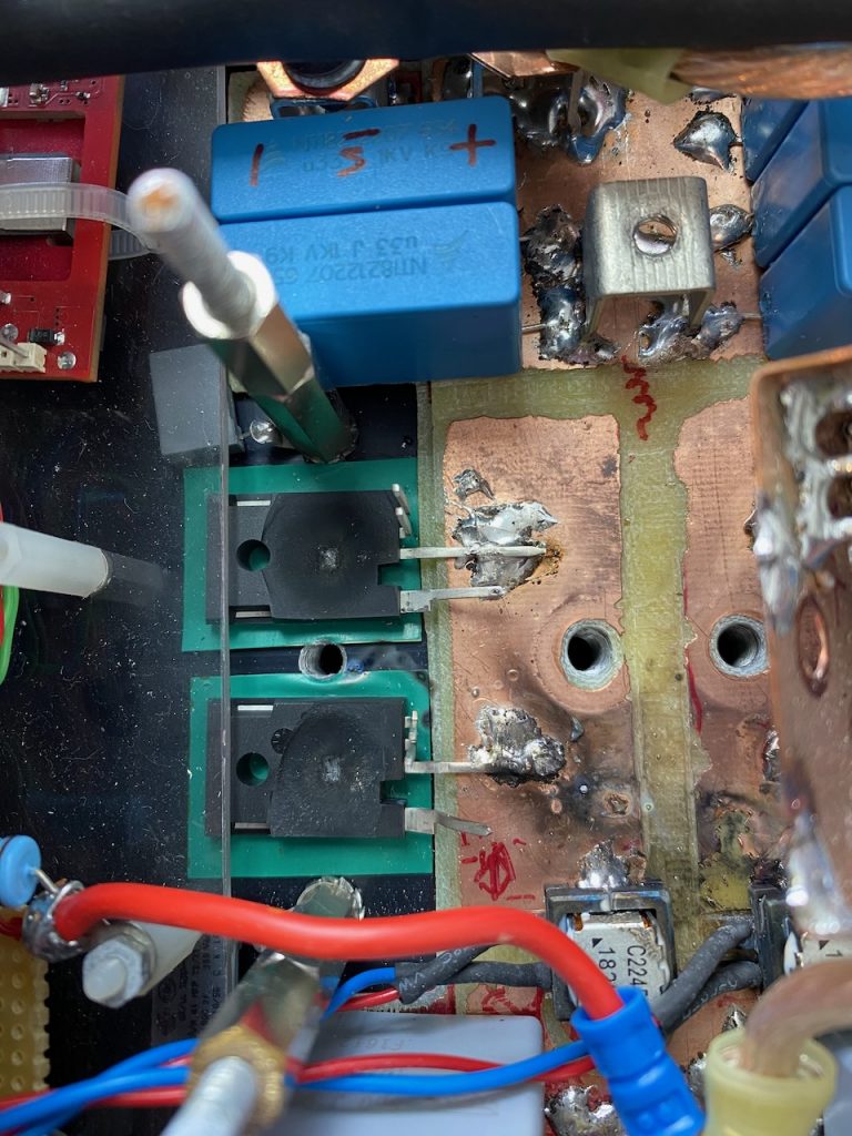
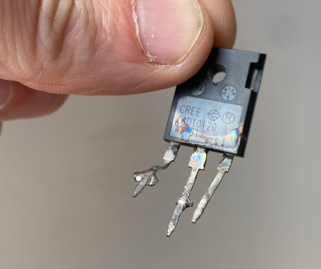
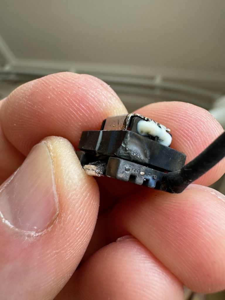
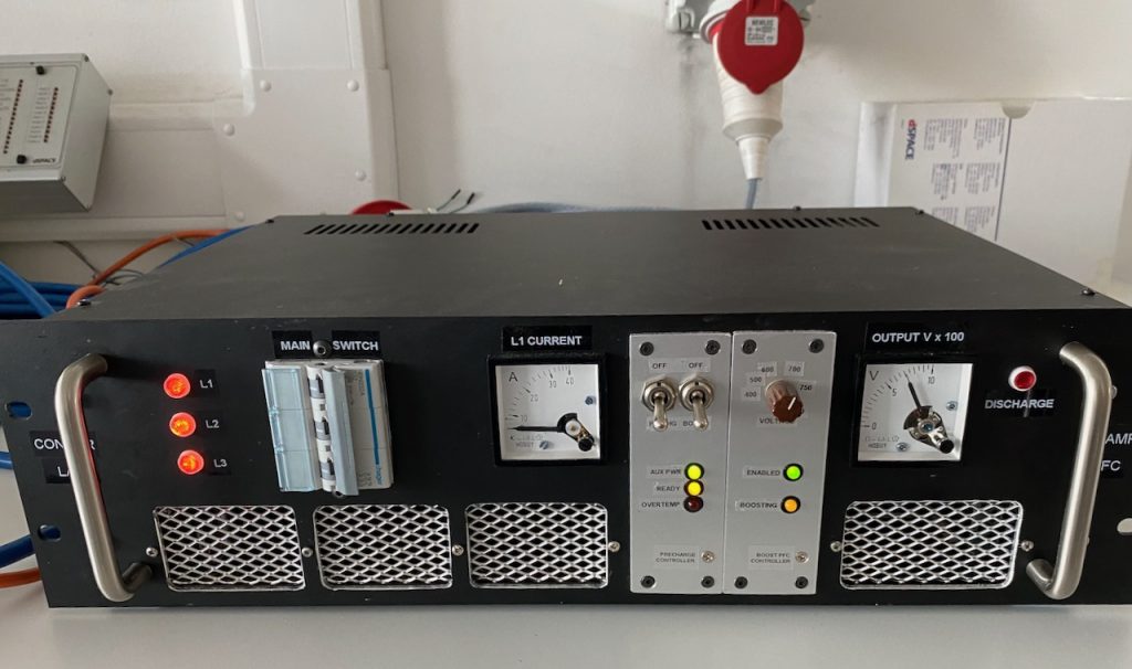
I started by investigating the PFC. The innards were well and truly splattered. Both SiC MOSFETs had cratered, the legs of one boost diode were partly eaten away, and a thin layer of vaporised copper covered everything. Even the ferrite core of one of the current transformers had partly melted.

Clearly a quite impressive arc flash had taken place. I think the most likely explanation is that something damp and conductive got in between the boost diode legs and caused the flashover. An arc here would have connected all of the charged DC bus capacitance (4400uF total at 750V!) to the MOSFET drains, causing them to fail explosively from massive overcurrent as soon as they next turned on.

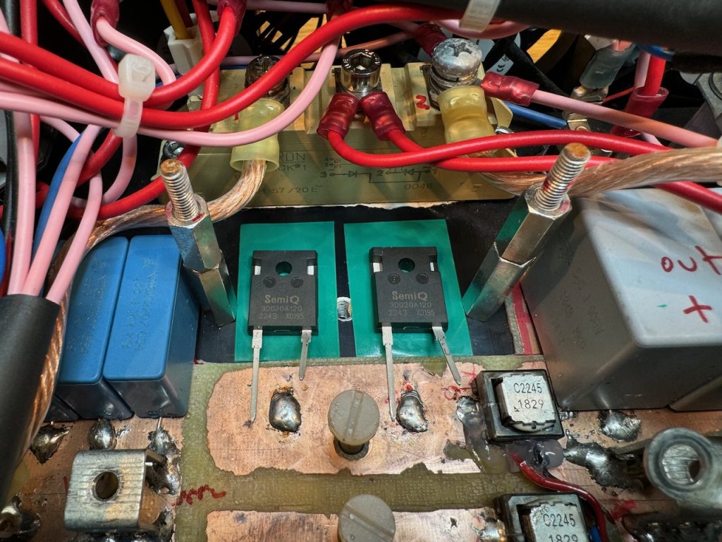
Amazingly the old diodes tested good, though the copper-coated one had a somewhat lower forward voltage. I replaced them anyway with these SemiQ parts that have double the pin spacing.

The annihilated Cree/Wolfspeed SiC MOSFETs were replaced with Infineon IMZ120R060M1HXKSA1.

I forgot to order a replacement CT, so I reinstalled the burnt one with a generous amount of hot glue. It still tested ok for continuity and primary/secondary insulation resistance, and the inductance was reasonable, if a bit lower than its undamaged partner.

Power up was completely uneventful, though the pause while the control power supply gets going can be a bit unsettling. You can see that I added a test socket for viewing the inductor current while I had the unit apart.

It runs happily and the inductor current waveform looks reasonable. I tried overloading the DC output until the 20A breaker on my house circuit tripped, and it seemed to survive that fine.

As this is a post-hoc post, I can say that the PFC also survived Gaussfest 2024 including several performances of Ian Dunne’s theremin.

Dawncaps for Odin

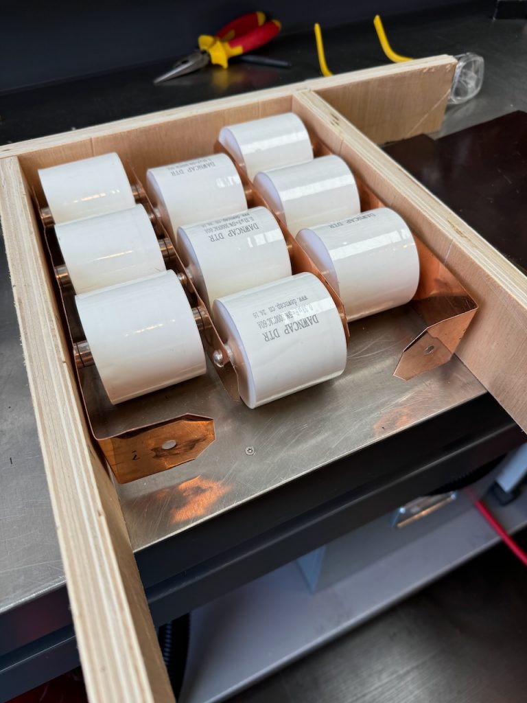
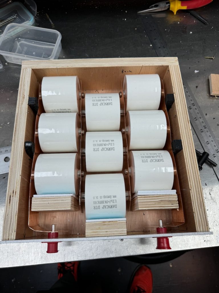
After my meltdown at EMF, I needed a new tank capacitor. I decided to risk buying some Dawncap DTR series from AliExpress. The 0.44uF seems to be the most popular model, but I went for the 0.33uF 3kV instead, and was careful to use what looked like the Dawncap official store.

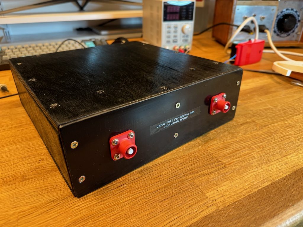
As I was in a bit of a hurry for Gaussfest I quickly made a plywood case with little thought to ventilation.

The front panel was made of plastic sheet (PVC?) as the plywood was too thick to give clearance for the connectors. These are 120 amp AMP Radsok connectors, also known as “Degson”.

Foam draughtproofing strip was used to stop the capacitors from rattling around, and the wooden case was painted black.

This capacitor is 10% bigger than the old one (0.33uF vs 0.3) but it seemed to perform exactly the same, no adjustments were needed to PLL frequency limits or primary tapping point.

Gaussfest 2023

This year’s Gaussfest was mostly remarkable for forgetting the drum machine. :<

Octavia is so full of stuff… but no drum machine πŸ™
Papplewick Pumping Station never fails to impress
Adam Horden helps wire up the 3 phase power supply while I pester him with questions about public liability insurance.
Jeb from Lords of Lightning ready to be zapped by Odin.
Part of my drum-machine-less set

Gaussfest 2022

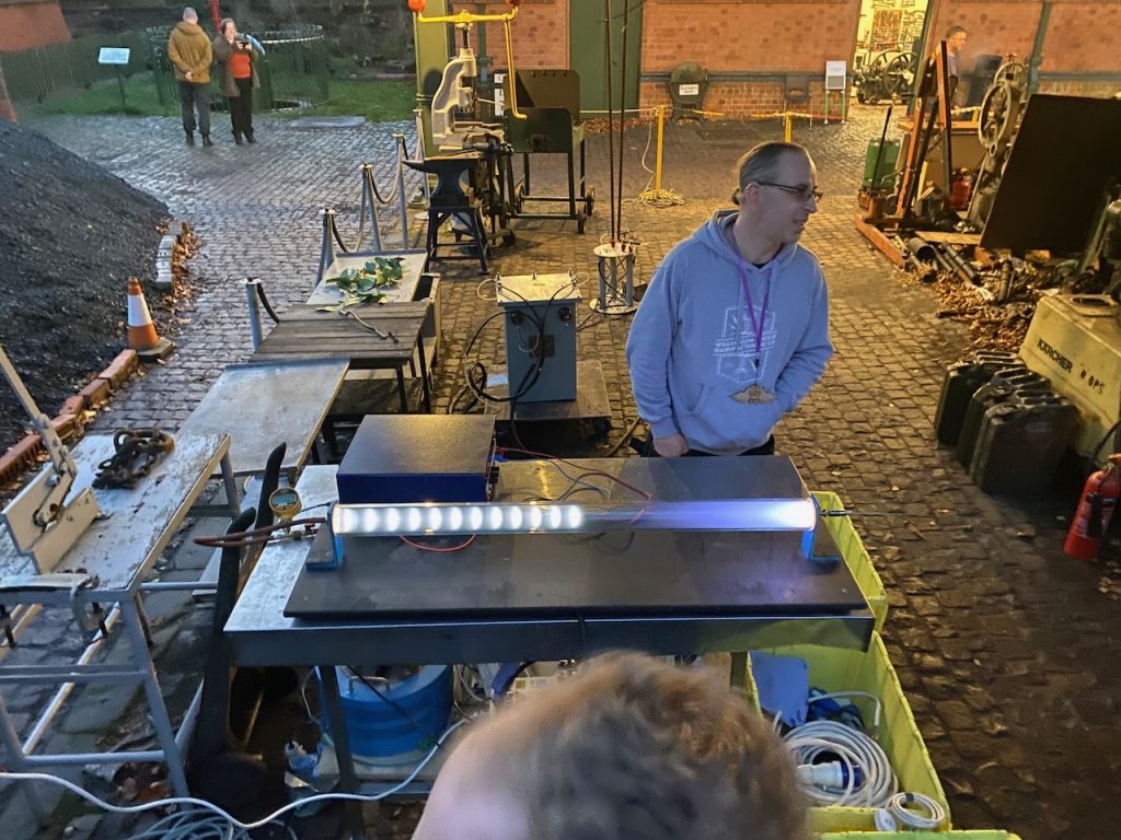
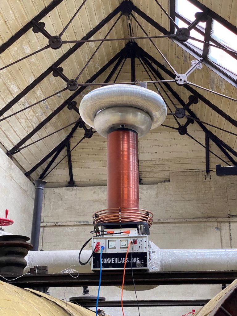
Odin made another appearance at Nottingham Gaussfest 2022. This year I got to run outdoors with a 32A 3 phase supply! A new spark record of 10ft was set, and a new power consumption record of around 15kW.

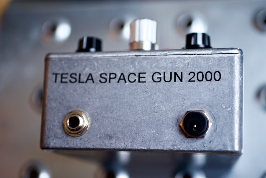
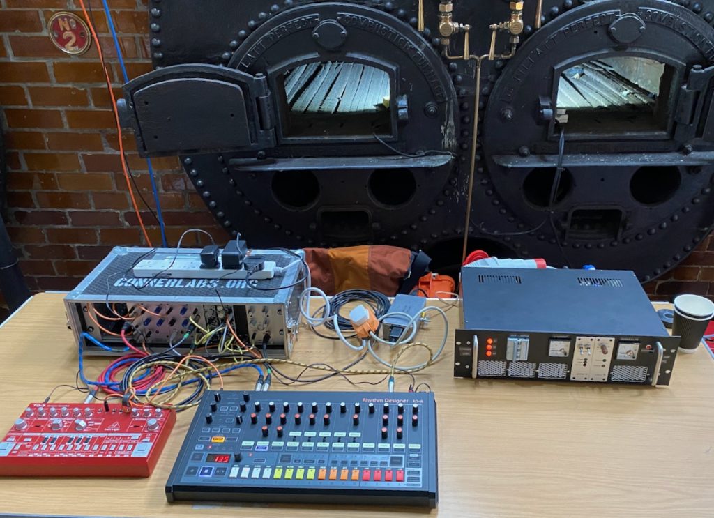
The Tesla Space Gun 2000 dub siren and drum machine were unleashed on an unsuspecting public.

I was so busy setting up and running the coil that I didn’t have a chance to get any photos.

But plenty of other people did.

this video was shot by Mark of tuopeek.com (Not toupees, autocorrect!) and gives a good impression of the whole event. Odin can be seen around 1:50.

if Tesla made an estate car…
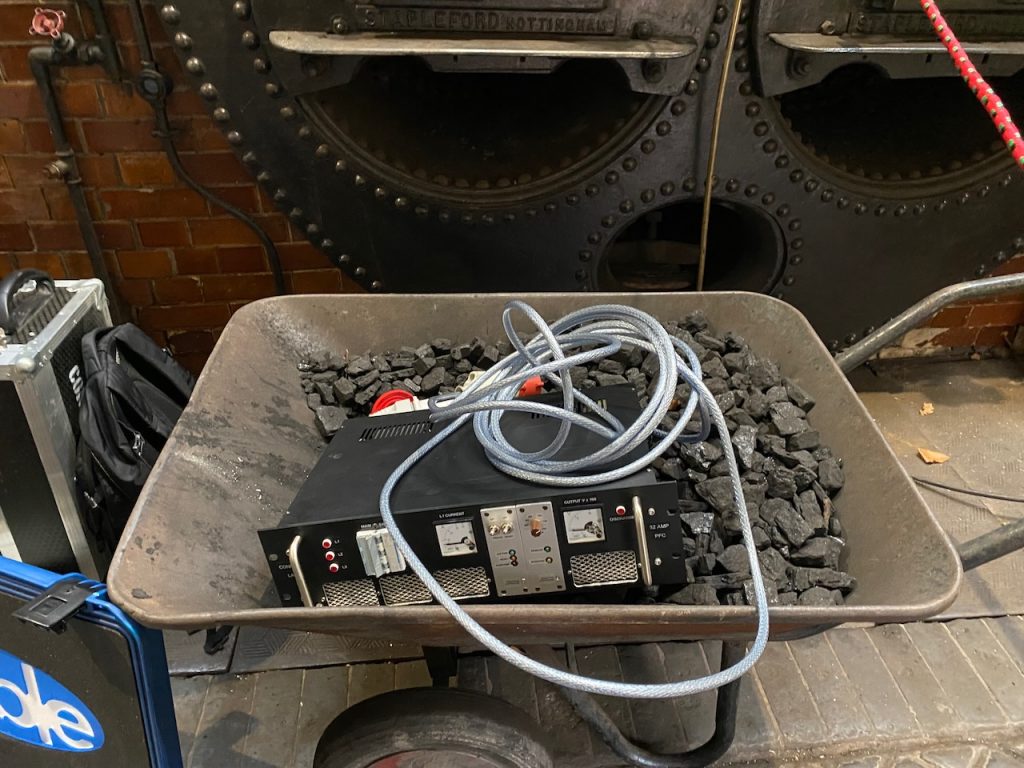
Going to bury this coal to offset my performance
some other really cool exhibits

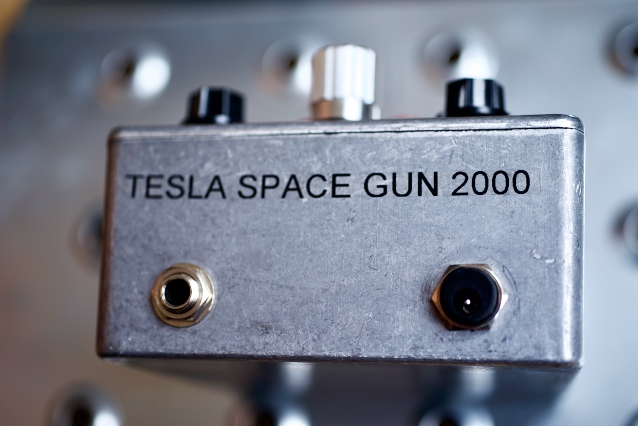
Tesla Space Gun 2000

For this year’s Gaussfest I decided to make a dub siren and connect it to Odin.

A dub siren is basically a very simple analog synth used to make sound effects for dub reggae. The original ones were a simple circuit with two 555 timers, but there are all sorts of variations on the theme. I was especially impressed by the Rigsmith GS1, which seems to contain some sort of toy sound effect IC.

I’m sure I had something similar mounted on the handlebars of my Raleigh Chopper in the 80s. How hard could it be to build one?

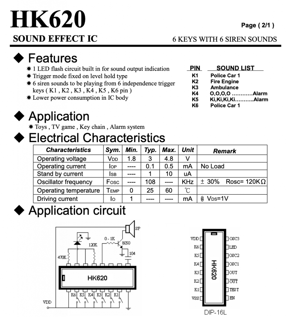
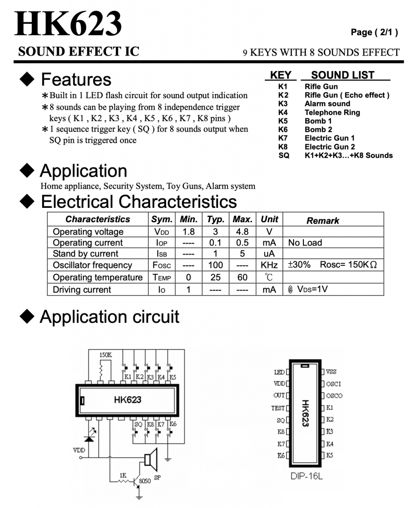
After some Googling and searching eBay, I found a surplus dealer selling some promising looking chips: the HK620 and HK623.

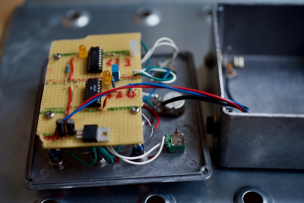
To make my dub siren I copied the data sheet application circuits almost exactly. The only change I made was to replace the timing resistor (“Rosc” in the datasheet) with a 1M pot in series with a 47k fixed resistor. I also added a 3.3 volt regulator so it could run off the standard 9V guitar pedal supply.

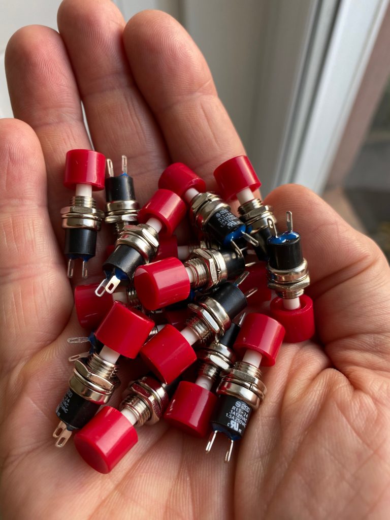
Buttons… So many buttons…
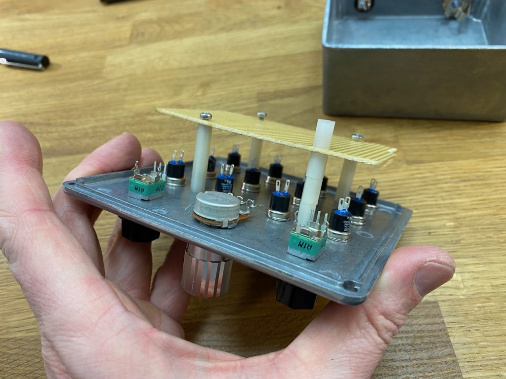
And a Hammond diecast box and some other bits and pieces

It sounds identical to the Rigsmith! Have they been shopping at Budgetronics too? πŸ˜€

Testing with a delay pedal and guitar amp

Gaussfest 2021

This bonkers event was organised by Extreme Electronics at Papplewick Pumping Station in Nottinghamshire. One of the few venues where Odin‘s full power can safely be deployed…

Check #Gaussfest on Twitter for more πŸ™‚

Odin set up in the boiler house. All steam powered, no EMC worries πŸ™‚
The control position next to the boilers
Tapping into 3 phase 415V supply
Can you identify the tune being covered?
More importantly, can YouTube’s content ID algorithm?

Look out for Mike “Electricstuff” with fingers in his ears

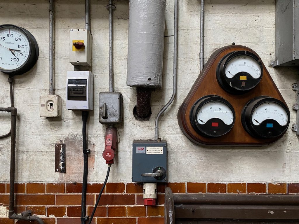
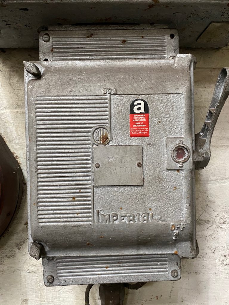
Boiler house switchboard… Yes my setup moved the meters πŸ™‚
Mmmm, asbestos
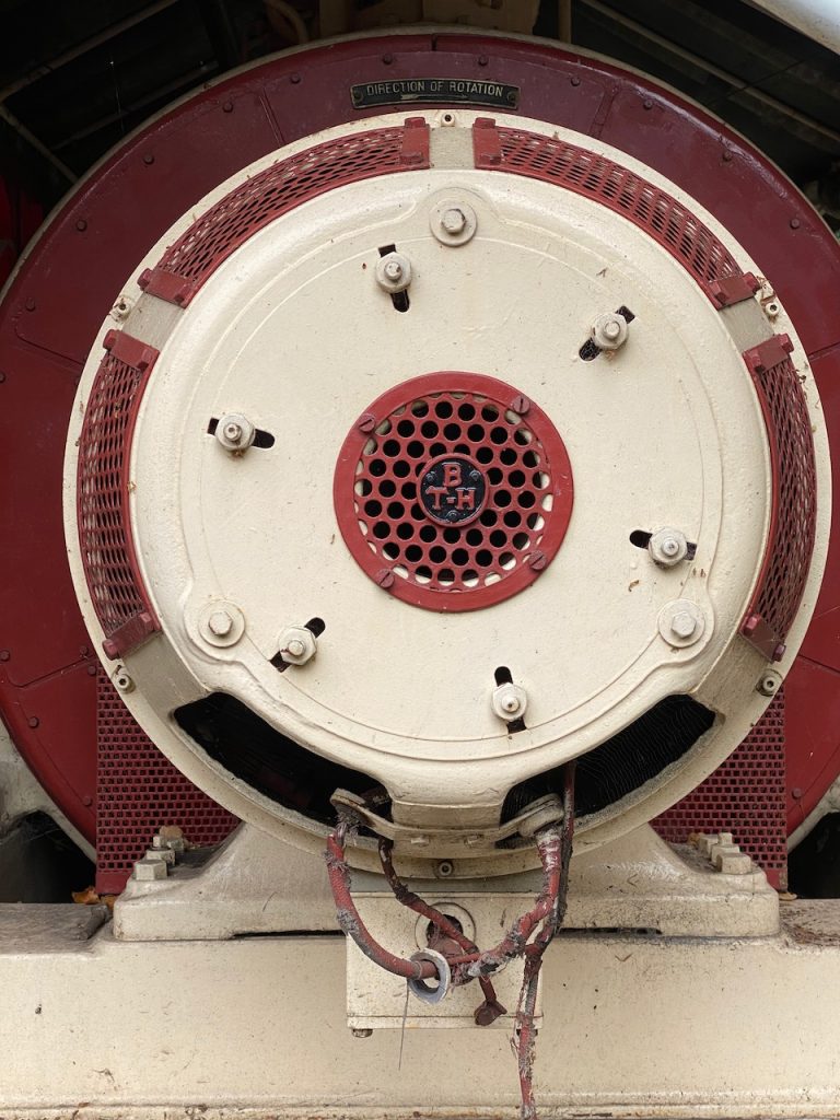
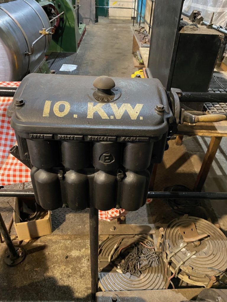
This generator was a bit too small to power Odin πŸ™
This one was too big
My performance did actually use about 10kW
An event like this would not be possible without defibrillators and a tea room.

PFC part 11: 3 phase test

Finally the long awaited test happened πŸ™‚ (you can read all posts about the PFC here)

We plugged it into the 3 phase outlet and it started up normally! πŸ˜€

When smashed with 750V the Tesla cabin heater would draw an impressive amount of power while warming up. Unfortunately the steady state power draw was only about 2kW, probably something to do with the rather weak fan cooling it.

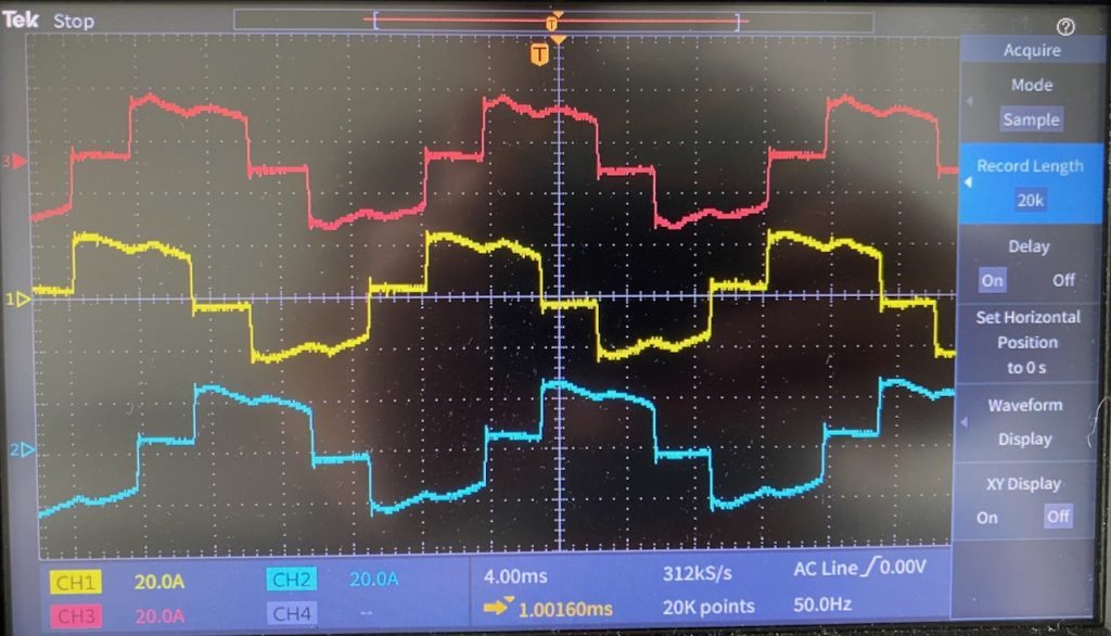
The PFC line current waveforms at (roughly) this 11kW output power level. No surprises here, they look exactly like the theoretical ones for this circuit. (Except strictly speaking the red one is upside down πŸ™‚ ) The theoretical power factor for this waveform is 0.95.

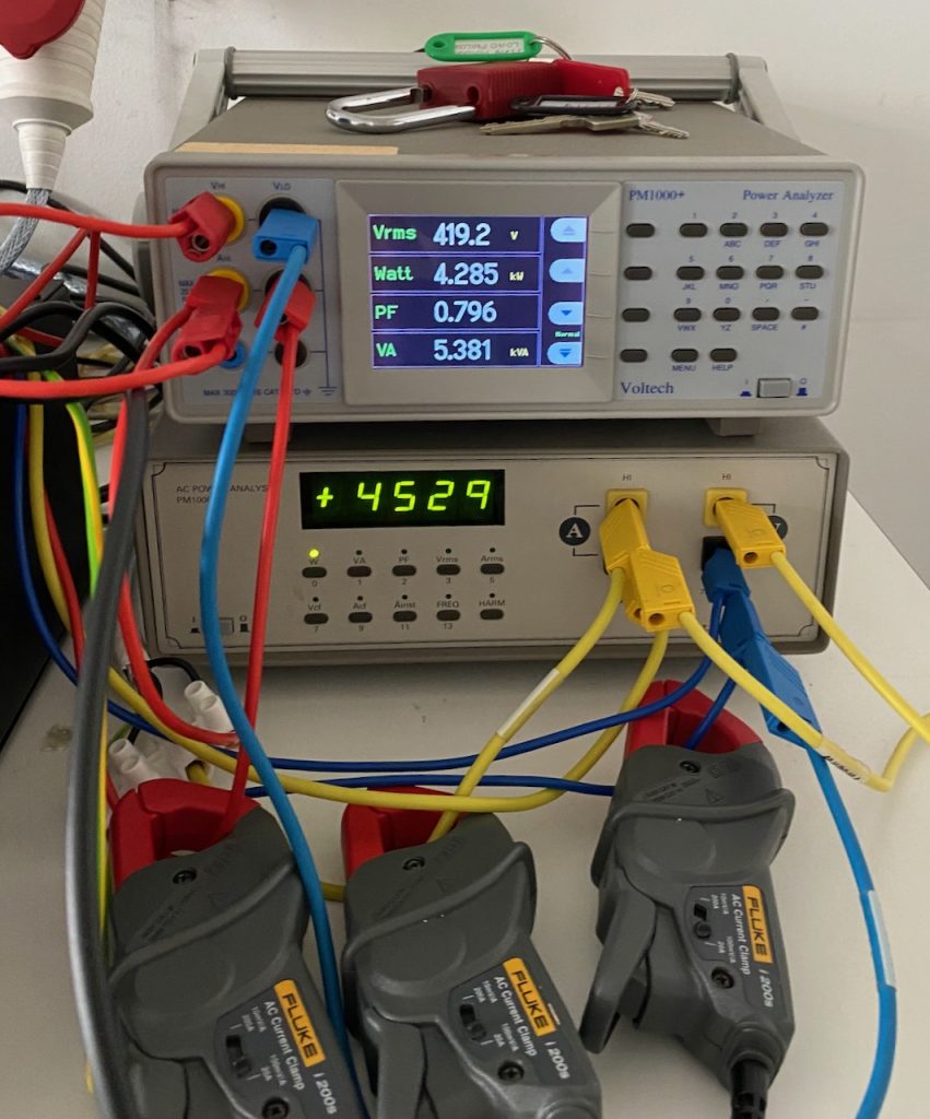
We don’t have a 3 phase power analyser in the lab, so I used 2 single phase ones on the input, according to the old “2 wattmeter method“. To be honest this didn’t work very well, as the power drawn by the PTC heater was always changing, and it was impossible to make sure the 2 meter readings corresponded to exactly the same time. Also, the PF reading is rubbish due to the inherent 30 degree phase shift: to get the actual PF you have to plug the wattage readings into a complicated formula.

When the heater reached steady state, I measured an input power of 2000W, an output of 1900W, and a power factor of 0.96. From an academic point of view it would have been nice to measure the efficiency at higher powers, I expect that 100W is mostly switching losses and the efficiency will increase with heavier loads.

The main goal was to get confidence that the PFC would work at its first gig, and this has been achieved πŸ™‚

PFC Part 1: Background

I decided it was time to build a new power supply for Odin with power factor correction. (See all posts on the PFC)

Power factor what? To explain, we have to go back to the turn of the last century and the War of the Currents. Alternating current won so all of our mains supplies are AC. However, solid-state Tesla coils, like most power electronics, run off DC. Odin needs several kilowatts of power at about 750V DC.

The simplest way to achieve this is to use a voltage doubling rectifier on the 240V AC mains. I used this in my previous large solid-state Tesla coil, the OLTC2, with one small refinement. I used SCRs instead of diodes to allow soft starting and varying the output voltage.

The major drawback of this circuit is a very poor power factor, especially at reduced output voltage. It is particularly bad in a DRSSTC, as it has a huge capacitor on the DC bus for energy storage, and the rectifier charges this directly. I improved the power factor somewhat by connecting a large iron cored inductor in series with the incoming mains. This worked well enough, and you can see details of the old power supply here here and here.

Gate pulses, line voltage and line current waveforms from the old PSU running at low output voltage.

I used this same power supply topology in Mjollnir, Little Cook and Odin. There was no room inside the smaller coils for the passive PFC inductor, so I used a much smaller one, making the power factor even worse. The shortcomings really became apparent in a few shows I did with Odin. It performed really badly when running off a generator, and there were two venues with 3 phase supply that I couldn’t use.

After much thought I decided to go for the simplest possible solution: a boost PFC. These are very common in larger consumer electronics, and controller ICs and design information are readily available. It is also easy to modify for 3 phase input. Essentially you just replace the rectifier with a 3 phase one. The line currents aren’t nice sine waves any more, but the power factor is still greatly improved over a plain rectifier with the same filter capacitance.

Probably the biggest drawback for Tesla coil use is that the output voltage can only be greater than the peak value of the rectified input voltage. You are limited to a minimum of about 400V when running off 240V single phase, and 600V from a 415V 3 phase supply. This is a problem for me at least because I like to check the tuning at reduced voltage after setting the coil up at a new venue.

Eventually I persuaded myself that I could live with this and set to work designing a boost PFC.