PFC part 10.5: Don’t contact me, I’ll contact you

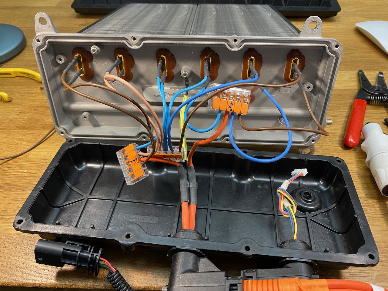
Another problem I have with the cabin heater testing (And the PFC testing πŸ™‚ ) is that the PFC is not designed to start up into a load. This isn’t a problem for the intended application, as the Tesla coil won’t draw any current until it’s commanded to. But to power a resistive load, I have to use a switch to connect the load after the PFC has started up.

For the previous immersion heater tests I used an ordinary 240V AC rated switch. This will make a DC circuit, but won’t break it: the arc simply won’t go out until the entire switch is incinerated. Of course if you’re reading this there’s a fair chance that you actually enjoy burning things to a crisp with electric arcs, but I have to be on my best behaviour to get the keys to the 3 phase outlet at work, and proper DC rated contactors are getting cheaper anyway thanks to the proliferation of electric vehicles.

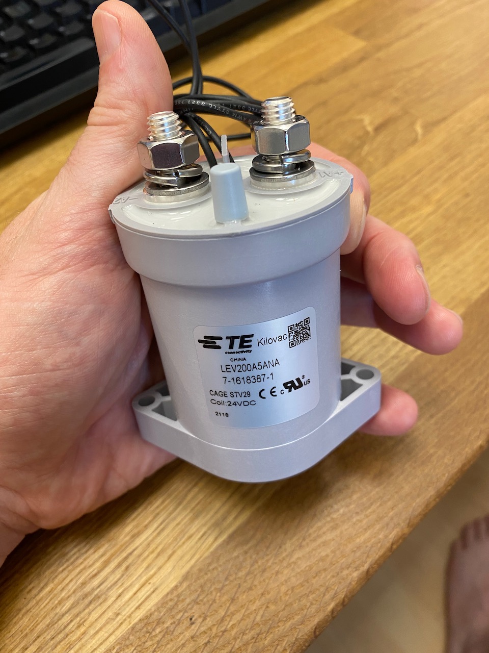
The Kilovac LEV200 has hydrogen filling and a permanent magnet to blow out the arc. It’s good for several hundred amps at 900V DC.

As one might expect, it makes a satisfying clunk.

Tesla Model 3 cabin heater teardown

I needed a high power dummy load that was a bit more health and safety friendly than my bucket of immersion heaters. I investigated lots of possibilities until I eventually found a Tesla Model 3 heater matrix on eBay. The Internet said it could draw up to 6kW, and being PTC, it shouldn’t catch fire if I forget to turn the fan on, which would look great on a risk assessment. So I went for it. πŸ™‚

The lid is held on by penta-lobe screws with a tamper-proof peg in the middle. There was nothing in my collection of tamper-proof bits that would fit, but a sturdy flat-bladed screwdriver worked quite well after Dremeling a new slot or just jamming it in hard enough to break off the peg. πŸ˜€

Ooh, fancy! What does all this stuff even do?

There appear to be 6 separate PTC elements, each with low side switching by a 600V IGBT and non-isolated gate driver.

To the left of the IGBTs is a voltage divider and low side current shunt, and on the right an isolated CAN interface and DC-DC converter. Handling CAN communications and A/D conversion of the voltage and current signals, we have an 8 bit ST microcontroller (probably sharing its 0V rail with DC bus negative)

Of course I immediately set to work reverse engineering the CAN protocol so I could command it to connect its elements in 2 groups of 3 for 800V input. Oh wait that’s not gonna work πŸ™ we need a hardware solution…

The heating elements were connected to the PCB by spring clips that released quite easily, but the PCB was stuck firmly to the aluminium enclosure with thermally conductive glue. I freed it with the old embedded programming trick of heating the enclosure with a heat gun and prying with a paint scraper. (sadly this doesn’t work any more in Python 3 πŸ˜‰ )

With the PCB removed we can see the terminals for the heating elements, looks as if some sort of spade terminal should fit nicely. (Also note the little nodule at bottom right which appears to be for cooling the CAN transceiver chip.)

And after a pulsating second half the score is Wago 221, CANbus 0. πŸ˜€