Author: Steve
-
Reaping time and sheeping time
Dear reader, I apologise for the lack of blogging recently. Here is a double helping.
First of all, I’ve been having great fun with Reaper. Digital audio workstation software written by the charmingly named Cockos Inc. I remember trying an early version years ago and hating it, but it has come a long way. I’ve tried most of the DAWs, and I think Reaper is now my favourite, especially when you can buy a personal-use license for 60 bucks! (I bought it.) It is available for Mac and Windows, and the bundled collection of plugins isn’t half bad.

My Reaper recording setup. To all electronics experts reading, I apologise for placing the setup so near a radiator! 🙂
So that’s reaping time, but what about the sheeping time? Well you know the old problem, when you need to edit the DNA of a cloned sheep but all you can find is an ancient gene splicing program that runs on classic Mac OS. Happens to us all.
I obtained a copy of the SheepShaver Mac emulator for Windows, and a ROM file and ready-to-use Mac OS 9 disk image from redundantrobot.com. I put it all on my old Windows laptop for a test. And, it werked!
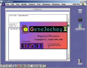
GeneJockey 2 running in Mac OS 9 on the SheepShaver emulator. -
Current dumping for dummies?
This article (series of them with any luck) is inspired by Nick de Smith’s Quad 405 project. He was getting better distortion figures than my Blameless build: 0.002% at 20kHz! And from an amp that operated in Class-B and needed no bias adjustment or thermal compensation, how could this be? I had tried to understand the current dumping concept before, and failed, but this time I was determined!
And this time I had some help from Keith Snook’s excellent resource on the Quad amps. His series of “DCD Mods” to the original Quad circuit actually make the operating principle clearer. And, he had a copy of the classic Wireless World article: “Current dumping – does it really work?” by Lipshitz and Vanderkooy.
So here is a simple, intuitive (and maybe even correct? 🙂 ) explanation of how current dumping works. Please refer to Snook’s DCD Mod-3 schematic, as well as the diagrams below, in which I’ve reduced the circuit to the bare minimum possible.
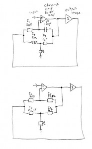
Current dumping amp simplified You can see that the amp consists of three parts. First, a Class-A, current feedback error amp. In the DCD Mod-3 circuit, the inverting input of this amp is TR2 emitter, the non-inverting input is TR2 base, and the output is TR7 collector.
Second, a hefty Class-B output stage that runs with no idle current. In the DCD Mod-3 this is TR8, TR9, TR10 and associated parts.
Third, what Nick de Smith referred to as the “Maxwell-Wien Bridge”. This is obvious in the DCD Mod-3 schematic. I’ve drawn it in the same way here, but I’ve labelled the components Z1, Z2, Z3, Z4 in accordance with Walker and Albinson’s original analysis.
Then, to make things a little clearer, I’ve drawn the circuit again, but replaced Z2 and Z4 with resistors, of values roughly equivalent to their reactances at 20kHz.
We’re now in a position to see intuitively how the circuit works. The error amp is looking at the output from the output stage, fed back to its inverting input through Z1, and comparing it to the desired audio signal on its non-inverting input. It amplifies the error by a factor of -(Z2/Z1) which is -100 in my circuit. This amplified error drives the output stage, like in any normal audio amplifier. But a portion of it is also fed forward directly to the speaker through Z3. This forms a potential divider with Z4, so the speaker sees the fed-forward signal attenuated by a factor of roughly Z3/Z4, which is 100.
So, the error got amplified by -100 and then attenuated by 100 again. It follows that the error gain to the speaker is just -1. In other words, an equal and opposite signal cancelling the original error, to give a perfect output. So, we’ve rederived the original Walker balance condition: Z2/Z1 = Z3/Z4, or Z1Z3 = Z2Z4 as Walker wrote it.
(I’ve taken some liberties with a “1” here and there: the potential divider really attenuates by a factor of 101. But so did Walker and Albinson and everyone else. I’ve also assumed that the output stage’s output impedance is negligible, and its input impedance is high enough not to load the error amp down and kill the feedforward signal. Again, I believe these assumptions were also made in the Quad 405 design.)
However, as every amplifier geek knows, Z2 is a capacitor and Z4 is an inductor. In fact, I remember Quad’s full page ads in the hi-fi press, that showed nothing but a picture of the inductor and the Queen’s Award logo.
Intuitively, what now happens is that the error amp integrates the error, but Z3 and Z4 are now a high-pass network that differentiates it again, so the feedforward works just the same as if Z2 and Z4 were resistive. But using reactances leads to some elegant synergies: each one ends up doing at least two good things at once, hence presumably the Queen’s Award.
Using a capacitor for Z2 gives classic dominant pole “Miller” compensation for the error amp, with all the associated benefits.
Using an inductor for Z4 saves power, isolates the output stage from nasty capacitive loads, and low-pass filters the remaining distortion harmonics.
Indeed, Z2 is the compensation cap, and Z4 the output coil, that most classic power amp designs need anyway. The only component that a classic amp doesn’t have is Z3. This suggests to me that an ordinary amp could be converted to a current dumper by just adding a resistor from the driver stage through to the speaker end of the output coil. (It also suggests that Quad’s ads should have showed a 47 ohm resistor instead of an inductor.)
A current-feedback amp with a hefty driver, like the Alexander, seems like it would be the best candidate, but I think it should be possible with a “Blameless” type voltage-feedback circuit, too. The only complication is that when you go to voltage feedback, Z1 isn’t a single resistor any more. Its effective value, as far as bridge balance is concerned, is the attenuation through the feedback network, divided by the input stage transconductance.
I could be wrong, but if this is true then the usual Blameless values give a value for Z1 of about 2500 ohms. That means the output coil would need to be 5 times bigger, or Z3 5 times smaller. That makes it 8 ohms, so in order to drive it, the error amp becomes an output stage and we’re back to square one! So, the Alexander is a much more attractive candidate for conversion, as it has Z1 = 750 ohms and Z2 = 100pF, giving a value for Z3/Z4 similar to the Quad 405.
I’ll leave you with a puzzle: In the DCD Mod-3 circuit (and indeed every other Quad 405 circuit) what are D5 and D13 for?
-
Cordellicious results
So, the low distortion oscillator is all put together.
And it works very nicely.
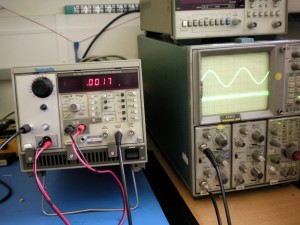
When the oscillator output is connected straight to the analyser input, it reads around the analyser’s specified floor (0.0021%) between 20Hz and 20kHz. The above picture shows 0.0017% at 1kHz with the 80kHz low pass filter engaged.
I took it home and used it to test my new Selfless Amp against the old Ice Block. The “Selfless” was somewhat degraded from its earlier bench test results because of hum induced by the transformer, but it still managed around 0.002% at 1kHz and 0.008% at 20kHz. (Both about 70W into 8 ohms: the readings at lower powers were inflated by the hum, and noise from the preamp.) The Ice Block couldn’t match this with 0.005% at 1kHz and 0.015% at 20kHz. In fact, one of the channels had 0.3% and whacking the amp made it jump around frantically. (The distortion reading, not the amp itself! :p) Turned out the speaker relay was bad, which gives me an idea for another project…
-
Cordell oscillator success
Well, the Cordell low distortion oscillator worked a treat! It didn’t work right away: I left a connection out of the PCB. And then I didn’t have a TL074 chip, so I tried a LMC660, and the chip blew up for some reason, which had me puzzled.
(I just checked the LMC660 datasheet: It’s specified for 15V total supply voltage. I fed it +/-16, a total of 32V. Whoops.)
Then, Cordell’s schematic calls for a 2N4091 JFET, a device with a high Idss and low on-resistance, but I couldn’t find any of those. I tried a BF245C, but it wasn’t strong enough. The AGC loop just whacked the gate as far positive as it could go, trying to turn the JFET “more than full on”. So I kept adding more of the things in parallel, until I saw the AGC go negative by a volt or two. I ended up with 5 of them, bodged onto a piece of stripboard.
A J111 would probably have been a better choice. These are the ones Douglas Self recommends as analog switches in “Self On Audio”, and they have a similar 30 ohm Rds(on). JFETs are so variable, though, you never know what you’ll get.
Frequency control with the “Blue Velvet” pot works great! There’s no noticeable amplitude bounce. Well, except for the fact that it’s backwards: anticlockwise to increase. I couldn’t see any easy way to dismantle the pot and reverse the action.
And, first time on the distortion analyser: 0.0015% at 1kHz! 🙂 That’s better than the analyser’s own spec.
Stay tuned as we post some pics and stuff the thing into the spare bay of the DA4084.
-
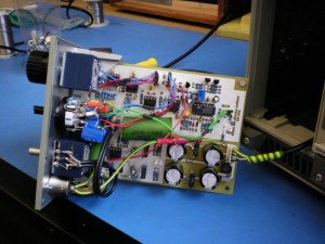
A “Cordell” low distortion oscillator
Recently, I accidentally broke my low-distortion oscillator, the “Williams Memorial”. The breadboard was such a mess, that I decided it would be almost as easy to just build the Bob Cordell design.
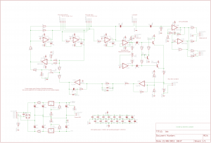
I altered the design a bit: I replaced the switched attenuator for a plain volume pot, made the output balanced, and swapped the three LM318 op-amps for a single TL074.
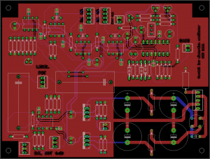
I put a rectifier, smoothing capacitors and regulators on board. I’m hoping that my THD analyser mainframe will have a couple of spare transformer windings to power it, and the whole thing can fit in the empty left-hand bay where the SG505 would have gone, if I ever had managed to find one.
For the frequency control, I plan to try a 50k Alps “Blue Velvet” pot. I’m hoping the superior tracking and wiper resistance, combined with Cordell’s non-linear amplitude control scheme, and the integrating nature of the state-variable oscillator, will make it usable. I’m also hoping it can be taken apart and reassembled with the shaft coming out of the other end, to make it reverse log.
If that doesn’t work, I’ll use a binary set of switches, or something. That worked surprisingly well on the Williams Memorial. Eventually I’d like to try with 4066-type analog switches in current mode.
Anyway, here’s the schematic and a preview of the board.
-
Tektronix 7603 mainframe repair
Last week I was given a big heap of surplus test gear. It included a Tek 7603 oscilloscope mainframe. I already have a R7603, so it was nice to get another one, but sadly it was sick. On applying power, it just sat there, dead in the water, with wisps of smoke coming from the regulator board.
First of all I downloaded the service manual from bama.edebris.com.
Then I noticed half of the power rails were missing, as was the 130V rail fuse on the regulator board. Someone had obviously been at it before me. I replaced this fuse, and it blew immediately with a sizeable flash and pop.
It turned out that several transistors on the regulator board had failed, some short, some open. I replaced the TO92 ones with 2N5551 (NPN) and 2N5401 (PNP) and the larger metal can ones with 2N2219s, except for one that looked like it needed to stand a higher voltage, so I got a MJE340 and jammed it into the socket. The smoke had been coming from a crispy-looking 1.2k resistor which I replaced too, even though it still measured 1.19k.
After doing this, all rails were correct, and the unit powered up. However ALT mode wouldn’t work. I replaced a 7474 IC on the logic board (with a 74LS74 as I had no originals) and that fixed it.
Then, the readout wouldn’t work. On closer inspection, there was no readout board: I suppose it must have been optional.
The focus was still a bit blurry with the focus knob cranked all the way, but adjusting the focus preset in the HV box cured that.
Last of all, the graticule lights wouldn’t work. Usually it’s because all the bulbs are blown, but this time it was because the cable assembly that drives them was missing, presumed lost by the last guy who tried fixing it. I found a similar 4-pin cable in a box of junk, and the lights came on.
Finally, just when I thought I was done, I noticed the channels were bleeding into each other in Chop mode. I tried replacing the other 7474, but it made no difference. In fact there was nothing wrong with the beam switching, the problem was that the Y amplifier wasn’t settling properly after each switch. Now a scope Y amplifier is a major piece of analog voodoo: it contains dozens of tweaks to compensate its own frequency response, and that of the delay line. My refusal to settle had a time constant of about 50us, though, and the slowest trim listed in the service manual was 50ns, not a lot of use. However the schematic also showed two networks for compensating slower “thermals”, and it turned out that the trimpot in one of these had gone open circuit. I replaced this and since there was no trim procedure in the manual, I just tweaked both networks for minimum bleed between channels. I got it better than my other 7603.
I love how you can take a 40 year old piece of Tektronix gear, and you can find the schematics and fix it in a morning with parts that are lying around the place. They just don’t make ’em like that any more. Now it’s time to have a go at the HP 141T spectrum analyser. 🙂
-
Blameless finished!
Here it is, pretty much done! The weather was pretty bad this weekend, so I spent most of it in the workshop, wiring everything up.
Besides the stuff I’ve already written about, there is a soft-start module (built rather messily on a tagboard), and a preamp/protection PCB. This contains Douglas Self’s anti-thump and DC offset protection circuit, a thermal cutout circuit using the spare diodes in the ThermalTrak power transistors for junction temperature sensing, and a balanced line input stage using the INA137 and NE5532.
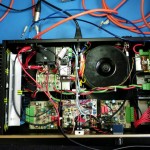
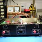
Here are some pics.
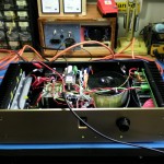
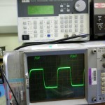
Gut Shot 1 The 10kHz square wave response, just short of clipping, into a dummy load.
I’ll do some whole-system THD measurements some other time. (I broke the Williams Memorial Oscillator. 🙂 )
-
Power up, distortion down
I did some more work on my Blameless amp project. First of all, I built another output stage, so I now have two output stages, but still only one driver board. Then, I improved my distortion measuring setup a bit. I shielded all the cables and rejigged the grounding, which reduced the oscillator + analyser floor to 0.0036%, with the 80kHz filter engaged.
With this extra resolution I was able to do some more tweaking of the Blameless. I found the following issues:
The MJE350 transistor in the output stage pre-driver is much slower than its MJE340 “complement”. I replaced it with a MJE15033. This allowed me to reduce the anti-sproggie resistor on the base. I was running 100 ohms on the NPN side and 200 on the PNP side, so I changed both to 150 and retried the reactive load test. There were no parasitics, and hopefully I’ll get a bit more power before clipping now.
I was only running about half of the amount of feedback that Douglas Self used in his experiments. (I used the same input stage gm and compensation capacitor as he did, giving the same open-loop gain at 20kHz, but I designed for twice the closed loop gain.) To fix this, I reduced the input pair’s emitter resistors from 100 ohms to 51.
The input doesn’t like being driven straight off the wiper of a 20k volume pot: when I buffered it with a NE5532 op-amp, the noise and distortion went down. I think Douglas Self implicitly designed all his circuits to run best with a 50 ohm source impedance, because that’s what an Audio Precision test set has. 🙂 He runs the input transistors at 2mA for high slew rate and lots of gm, but the downside is lots of noise current and a low AC input impedance. So, in the finished unit I’ll buffer the volume pot.
Adding a DC offset trim and tweaking it for minimum offset also reduced 2nd harmonic at high frequencies. Again this is what Self’s theory of the input stage predicts.
The biggest improvement came by swapping out the expensive PNP matched input pair for a pair of ordinary transistors that just had high beta: BC213C’s with 350 min. as opposed to the 100 typ. of the MAT03. Saving money while boosting performance, that’s more like engineering than hi-fi 🙂
When I was finished with all this, I had a THD+N figure at 100W, 1kHz, 4.7 ohm load, of… 0.0036%! The same as the oscillator itself. The residual also looked identical to the oscillator’s own. At 100W, 10kHz, I got 0.008%, and this decreased to 0.0065% at 100W, 20kHz. (Because of the 80kHz filter, I assume.)
The 1W figures were slightly higher than the above, but from examining the residual, the extra seemed to be mostly the noise floor of the amp and oscillator, rather than crossover distortion.
These are pretty much the best results I’ve had, and I can almost imagine that if I had an Audio Precision, I’d be seeing the kinds of figures that Self claims.
-
What’s all this Black Swan stuff, anyhow?
I’m somewhat of a fan of Nassim Nicholas Taleb’s book, “The Black Swan”. To me at least, the book is about the human tendency to tell ourselves stories about reality, and then substitute the stories for what is really there. This idea should be familiar to any student of Zen. Taleb calls it the narrative fallacy, and explores its messy implications in business and finance.
It struck me today that this is how electronic design proceeds, too. We start by telling ourselves a story about how the proposed circuit will work. The electrons will go down here, some of them will go this way, this part will oscillate at 123 megahertz, and so on. We either make it up in our heads, or orchestrate it on a circuit simulator, but in either case we are dealing with a Platonic approximation to the real circuit.
It follows from this that the lab bench is Taleb’s “Platonic fold”, where our narratives collide with the messy reality of what the prototype circuit actually does. This is the origin of the pearl of wisdom attributed to (the sadly late) Bob Pease or someone similar: that a circuit always works, it just doesn’t always do what you expect. Anyone who has done any practical work with electronics knows the brain-wringing feeling of struggling with a circuit built on wrong assumptions in this way. It simply refuses to do what you want, for no reason that you can see, because your reasoning is based on the same faulty assumptions. The best you can hope is that you have the “Aha moment” and come away with your narratives more firmly grounded in reality.
It also follows that by going into production with a circuit that doesn’t work the way you think, you invite it to start doing things that you didn’t expect when it gets out in the field. This can generate Black Swans in exactly the same way as Taleb’s example of running a hedge fund based on invalid mathematical models.
Usually the results are negative and your company simply goes bust, but once in a while you can benefit, as in Bob Pease’s tale of the Philbrick P2 op-amp. This was a groundbreaking product that contained about $5 worth of components, but delivered enough value-added to the customer that it could be sold for the price of a small car. The P2 made the company, even though (according to Pease) nobody in the company actually understood quite how it worked. But in spite of this they managed to produce it consistently and have it work reliably.
What’s more, if this is true then the world of electronics must have its “Fat Tony” characters, rather than being purely the province of “Dr. Johns” as one might expect. (For those unfamiliar with the book, you might like to mentally substitute Thomas Edison for Fat Tony and Nikola Tesla for Dr. John.) They are probably the same people that George Philbrick called lightning empiricists, after the fashion (though before the time, this being the 1950s) of Taleb’s skeptical empiricists. Indeed, Fat Tony would probably have wholeheartedly approved of the above mentioned P2, if he didn’t actually design it.
Anyway, that’s me on the narrative fallacy in electronic design. Next time I’ll write about the normal distribution and power laws. Taleb has his “Great Intellectual Fraud”, and communications theorists have their AWGN – “Additive White Gaussian Noise”. Until then, what are the odds of Bob Pease and Jim Williams dying the same week? I make it about 1 in 9 million, but sadly it happened, as Pease crashed his 1969 VW Beetle on the way home from Williams’ memorial service. Both were legends of analog electronics, and the impact is hard to overstate: it’s as if Jane Goodall and David Attenborough got trampled by the same elephant.
In a twist that Taleb may have found bitterly amusing, Pease had just self-published a book on safe driving, which didn’t sell.
