Blameless finished!

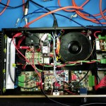
Here it is, pretty much done! The weather was pretty bad this weekend, so I spent most of it in the workshop, wiring everything up.

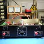
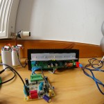
Besides the stuff I’ve already written about, there is a soft-start module (built rather messily on a tagboard), and a preamp/protection PCB. This contains Douglas Self’s anti-thump and DC offset protection circuit, a thermal cutout circuit using the spare diodes in the ThermalTrak power transistors for junction temperature sensing, and a balanced line input stage using the INA137 and NE5532.

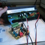
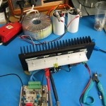
Here are some pics.

Gut Shot 1

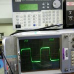
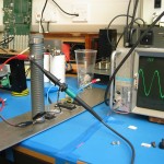
The 10kHz square wave response, just short of clipping, into a dummy load.

I’ll do some whole-system THD measurements some other time. (I broke the Williams Memorial Oscillator. πŸ™‚ )

Power up, distortion down

I did some more work on my Blameless amp project. First of all, I built another output stage, so I now have two output stages, but still only one driver board. Then, I improved my distortion measuring setup a bit. I shielded all the cables and rejigged the grounding, which reduced the oscillator + analyser floor to 0.0036%, with the 80kHz filter engaged.

With this extra resolution I was able to do some more tweaking of the Blameless. I found the following issues:

The MJE350 transistor in the output stage pre-driver is much slower than its MJE340 “complement”. I replaced it with a MJE15033. This allowed me to reduce the anti-sproggie resistor on the base. I was running 100 ohms on the NPN side and 200 on the PNP side, so I changed both to 150 and retried the reactive load test. There were no parasitics, and hopefully I’ll get a bit more power before clipping now.

I was only running about half of the amount of feedback that Douglas Self used in his experiments. (I used the same input stage gm and compensation capacitor as he did, giving the same open-loop gain at 20kHz, but I designed for twice the closed loop gain.) To fix this, I reduced the input pair’s emitter resistors from 100 ohms to 51.

The input doesn’t like being driven straight off the wiper of a 20k volume pot: when I buffered it with a NE5532 op-amp, the noise and distortion went down. I think Douglas Self implicitly designed all his circuits to run best with a 50 ohm source impedance, because that’s what an Audio Precision test set has. πŸ™‚ He runs the input transistors at 2mA for high slew rate and lots of gm, but the downside is lots of noise current and a low AC input impedance. So, in the finished unit I’ll buffer the volume pot.

Adding a DC offset trim and tweaking it for minimum offset also reduced 2nd harmonic at high frequencies. Again this is what Self’s theory of the input stage predicts.

The biggest improvement came by swapping out the expensive PNP matched input pair for a pair of ordinary transistors that just had high beta: BC213C’s with 350 min. as opposed to the 100 typ. of the MAT03. Saving money while boosting performance, that’s more like engineering than hi-fi πŸ™‚

When I was finished with all this, I had a THD+N figure at 100W, 1kHz, 4.7 ohm load, of… 0.0036%! The same as the oscillator itself. The residual also looked identical to the oscillator’s own. At 100W, 10kHz, I got 0.008%, and this decreased to 0.0065% at 100W, 20kHz. (Because of the 80kHz filter, I assume.)

The 1W figures were slightly higher than the above, but from examining the residual, the extra seemed to be mostly the noise floor of the amp and oscillator, rather than crossover distortion.

These are pretty much the best results I’ve had, and I can almost imagine that if I had an Audio Precision, I’d be seeing the kinds of figures that Self claims.
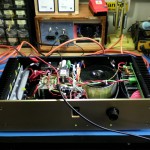
Blameless first sound! :D

Today, after much testing with various dummy loads, including the dreaded 4 ohm reactive one (which showed up some parasitics that I managed to get rid of) the Blameless was finally plugged into a speaker.

It werks!
It werks!

Attempts to measure the THD have so far failed. They really just show up the limits of my Β THD measuring system, which is currently no good for anything except finding gross faults.

For instance, the reading I previously got of 0.05% at 10kHz and 120W. When I took the amp out of circuit and connected the analyser straight to the oscillator, the THD reading increased to 0.09%.

The THD analyser does show up crossover spikes, though, if the output stage is underbiased. They were pretty much invisible by a bias voltage of 10mV per side (20mV total) which corresponded to 200mA total idle current. I set it to 13, which gives the 26mV total that some experts recommend.

Anyway, it’s working, and experimenter expectancy notwithstanding, not to mention lack of one channel, I swear it sounds better than my old MOSFET amp. Maybe there is something in Douglas Self’s claims of poor crossover distortion from MOSFETs. Once I get the other channel built and the system put together, I will make that low-distortion oscillator and do a THD shootout. Or an ABX test or something. Anyone want to lend me an Audio Precision test set? πŸ™‚

More Blameless progress

The Blameless project is grinding on!

.

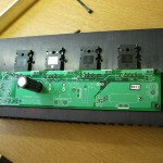
4-layer boards for the output stages were designed in Eagle and ordered from PCB Train. Some samples of the ONSemi NJL4281/4302 transistors with built-in thermal sensing diodes were obtained. The whole lot was fitted to a large heatsink using Sil-Pad A1500 high performance thermal pad stuff.

After testing using a bench power supply, it was connected to a large transformer, rectifier and some capacitors.

The power was turned on and amazingly it failed to explode.

More detailed info to come, but the maximum output is about 120-150W into 4 ohms, the THD about 0.05% or less at 10kHz and 120W (so should be nearer 0.005% at 1kHz) and the short circuit protection, thermal compensation etc. all works as planned.