This article (series of them with any luck) is inspired by Nick de Smith’s Quad 405 project. He was getting better distortion figures than my Blameless build: 0.002% at 20kHz! And from an amp that operated in Class-B and needed no bias adjustment or thermal compensation, how could this be? I had tried to understand the current dumping concept before, and failed, but this time I was determined!
And this time I had some help from Keith Snook’s excellent resource on the Quad amps. His series of “DCD Mods” to the original Quad circuit actually make the operating principle clearer. And, he had a copy of the classic Wireless World article: “Current dumping – does it really work?” by Lipshitz and Vanderkooy.
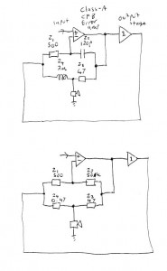
So here is a simple, intuitive (and maybe even correct? 🙂 ) explanation of how current dumping works. Please refer to Snook’s DCD Mod-3 schematic, as well as the diagrams below, in which I’ve reduced the circuit to the bare minimum possible.

You can see that the amp consists of three parts. First, a Class-A, current feedback error amp. In the DCD Mod-3 circuit, the inverting input of this amp is TR2 emitter, the non-inverting input is TR2 base, and the output is TR7 collector.
Second, a hefty Class-B output stage that runs with no idle current. In the DCD Mod-3 this is TR8, TR9, TR10 and associated parts.
Third, what Nick de Smith referred to as the “Maxwell-Wien Bridge”. This is obvious in the DCD Mod-3 schematic. I’ve drawn it in the same way here, but I’ve labelled the components Z1, Z2, Z3, Z4 in accordance with Walker and Albinson’s original analysis.
Then, to make things a little clearer, I’ve drawn the circuit again, but replaced Z2 and Z4 with resistors, of values roughly equivalent to their reactances at 20kHz.
We’re now in a position to see intuitively how the circuit works. The error amp is looking at the output from the output stage, fed back to its inverting input through Z1, and comparing it to the desired audio signal on its non-inverting input. It amplifies the error by a factor of -(Z2/Z1) which is -100 in my circuit. This amplified error drives the output stage, like in any normal audio amplifier. But a portion of it is also fed forward directly to the speaker through Z3. This forms a potential divider with Z4, so the speaker sees the fed-forward signal attenuated by a factor of roughly Z3/Z4, which is 100.
So, the error got amplified by -100 and then attenuated by 100 again. It follows that the error gain to the speaker is just -1. In other words, an equal and opposite signal cancelling the original error, to give a perfect output. So, we’ve rederived the original Walker balance condition: Z2/Z1 = Z3/Z4, or Z1Z3 = Z2Z4 as Walker wrote it.
(I’ve taken some liberties with a “1” here and there: the potential divider really attenuates by a factor of 101. But so did Walker and Albinson and everyone else. I’ve also assumed that the output stage’s output impedance is negligible, and its input impedance is high enough not to load the error amp down and kill the feedforward signal. Again, I believe these assumptions were also made in the Quad 405 design.)
However, as every amplifier geek knows, Z2 is a capacitor and Z4 is an inductor. In fact, I remember Quad’s full page ads in the hi-fi press, that showed nothing but a picture of the inductor and the Queen’s Award logo.
Intuitively, what now happens is that the error amp integrates the error, but Z3 and Z4 are now a high-pass network that differentiates it again, so the feedforward works just the same as if Z2 and Z4 were resistive. But using reactances leads to some elegant synergies: each one ends up doing at least two good things at once, hence presumably the Queen’s Award.
Using a capacitor for Z2 gives classic dominant pole “Miller” compensation for the error amp, with all the associated benefits.
Using an inductor for Z4 saves power, isolates the output stage from nasty capacitive loads, and low-pass filters the remaining distortion harmonics.
Indeed, Z2 is the compensation cap, and Z4 the output coil, that most classic power amp designs need anyway. The only component that a classic amp doesn’t have is Z3. This suggests to me that an ordinary amp could be converted to a current dumper by just adding a resistor from the driver stage through to the speaker end of the output coil. (It also suggests that Quad’s ads should have showed a 47 ohm resistor instead of an inductor.)
A current-feedback amp with a hefty driver, like the Alexander, seems like it would be the best candidate, but I think it should be possible with a “Blameless” type voltage-feedback circuit, too. The only complication is that when you go to voltage feedback, Z1 isn’t a single resistor any more. Its effective value, as far as bridge balance is concerned, is the attenuation through the feedback network, divided by the input stage transconductance.
I could be wrong, but if this is true then the usual Blameless values give a value for Z1 of about 2500 ohms. That means the output coil would need to be 5 times bigger, or Z3 5 times smaller. That makes it 8 ohms, so in order to drive it, the error amp becomes an output stage and we’re back to square one! So, the Alexander is a much more attractive candidate for conversion, as it has Z1 = 750 ohms and Z2 = 100pF, giving a value for Z3/Z4 similar to the Quad 405.
I’ll leave you with a puzzle: In the DCD Mod-3 circuit (and indeed every other Quad 405 circuit) what are D5 and D13 for?
Leave a Reply