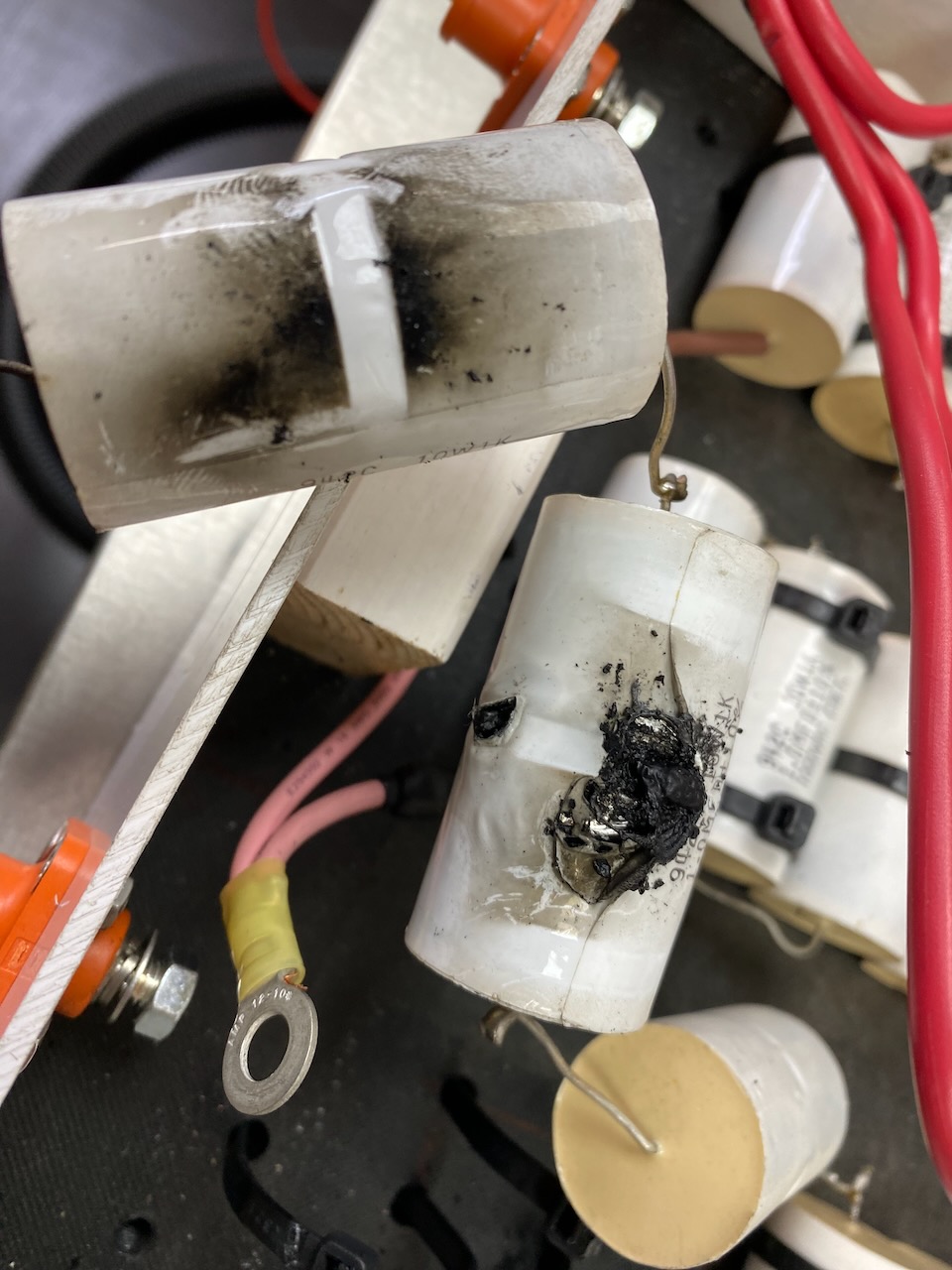
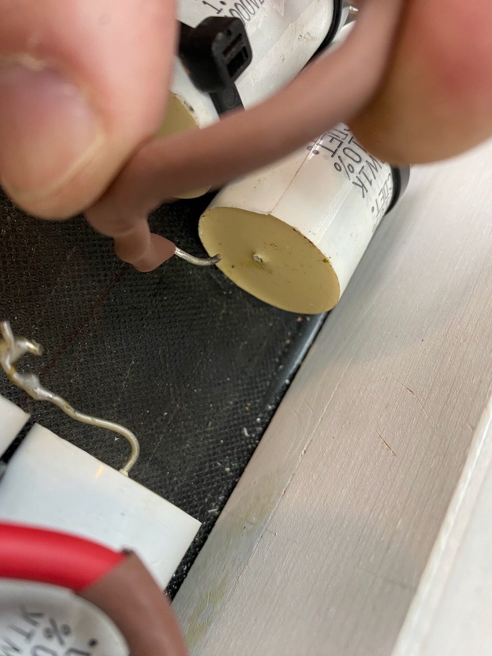
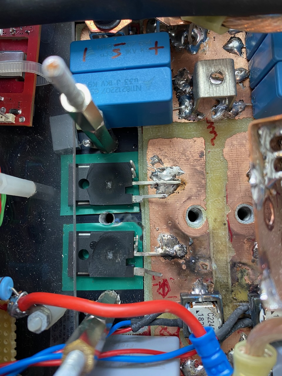
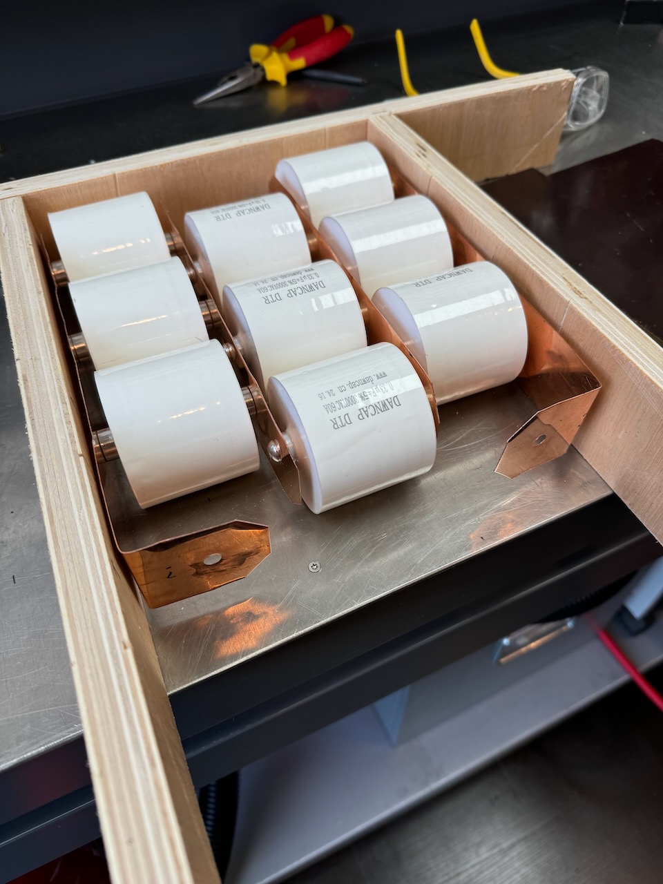
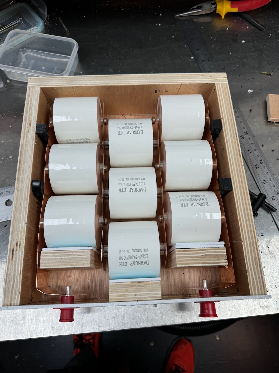
With the PFC sorted I turned my attention to the main coil unit. I started by replacing the melted tank capacitors. One had exploded, one looked a bit burnt, and the leg of a third capacitor came off in my hand.
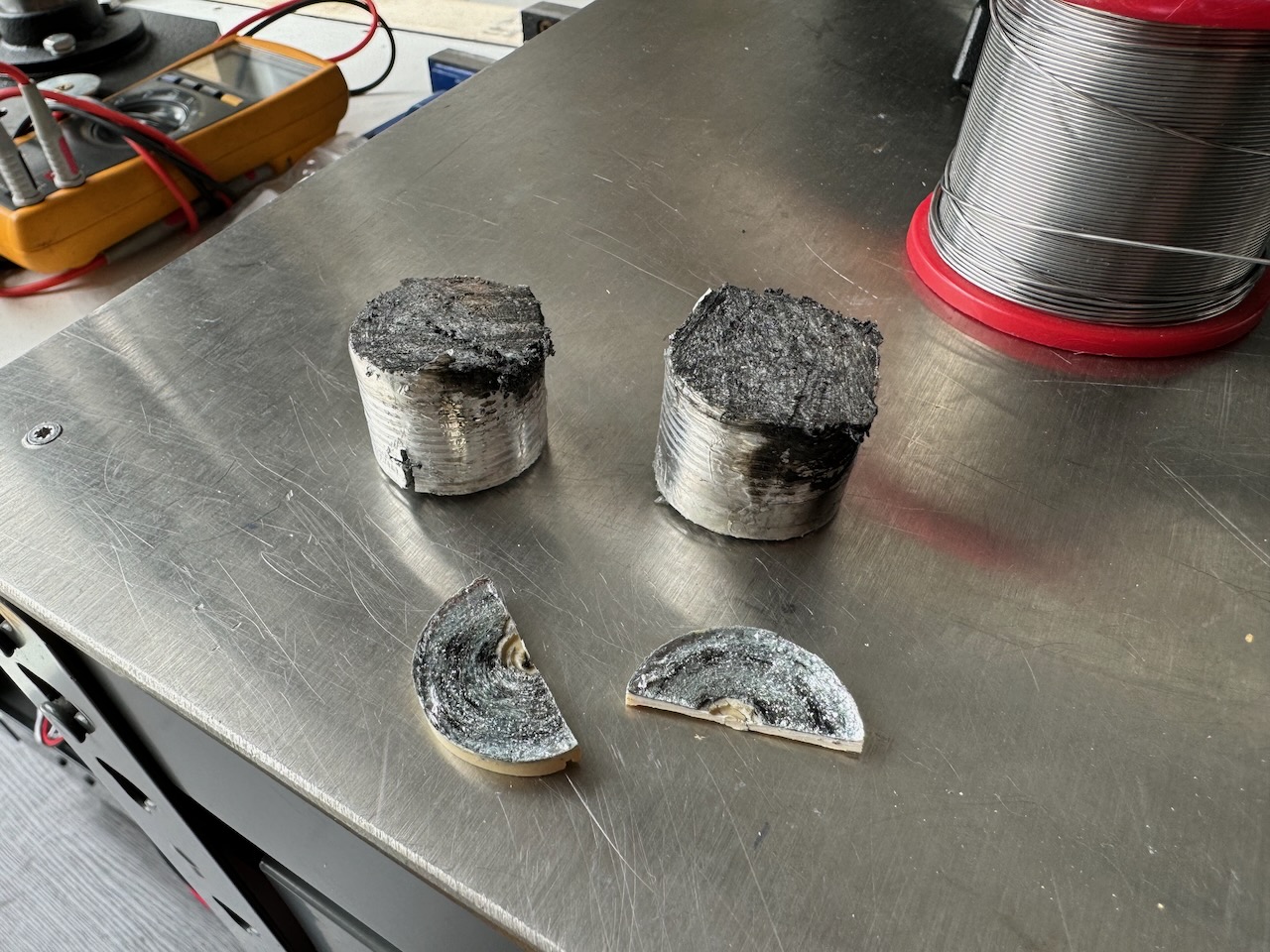
Out of curiosity I cut open the exploded capacitor. The whole inside was just a blackened mess.
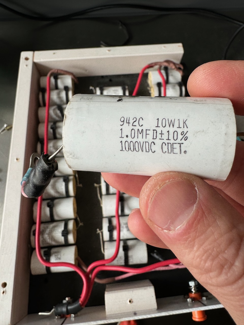
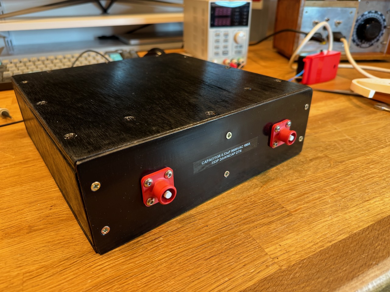
I bought a load of these Cornell Dubilier 942C series capacitors, 1uF 1000V, years ago for the OLTC 2. In Odin they are overloaded to about 3x their rated RMS current and crammed into an unventilated wooden box, so I’m not entirely surprised they failed.
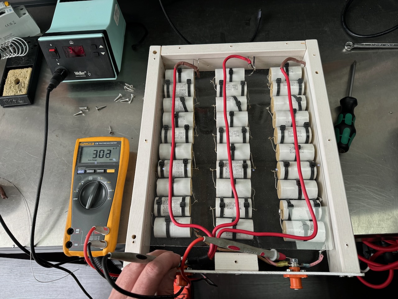
What did surprise me was that every other capacitor tested fine! I found replacements for the destroyed caps in my pile of Tesla junk and the capacitor bank was ready to go again!
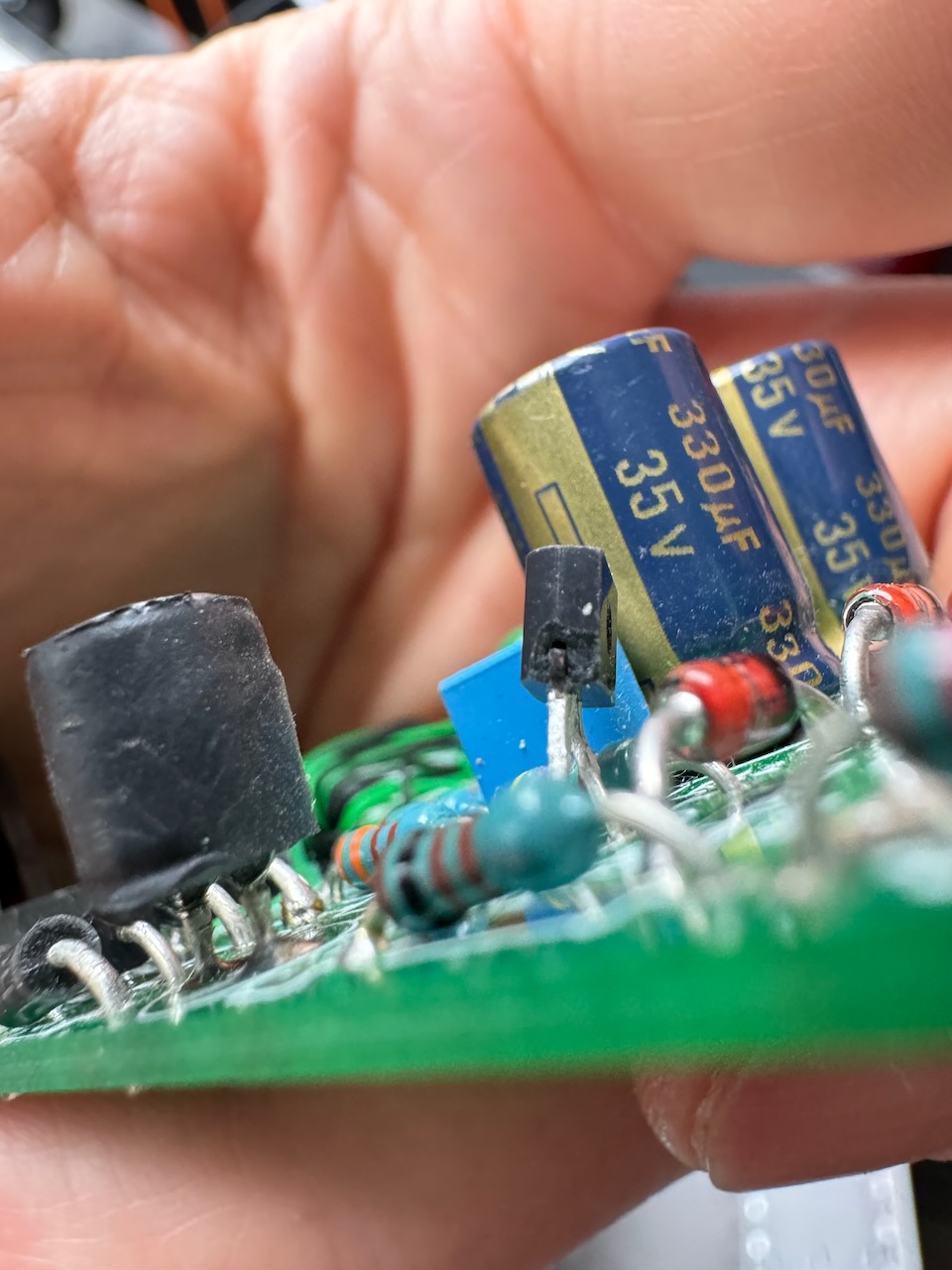
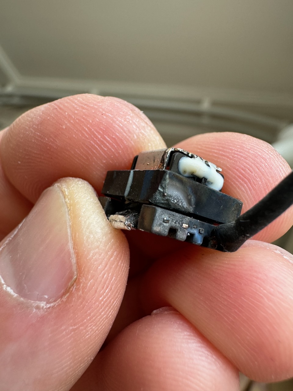
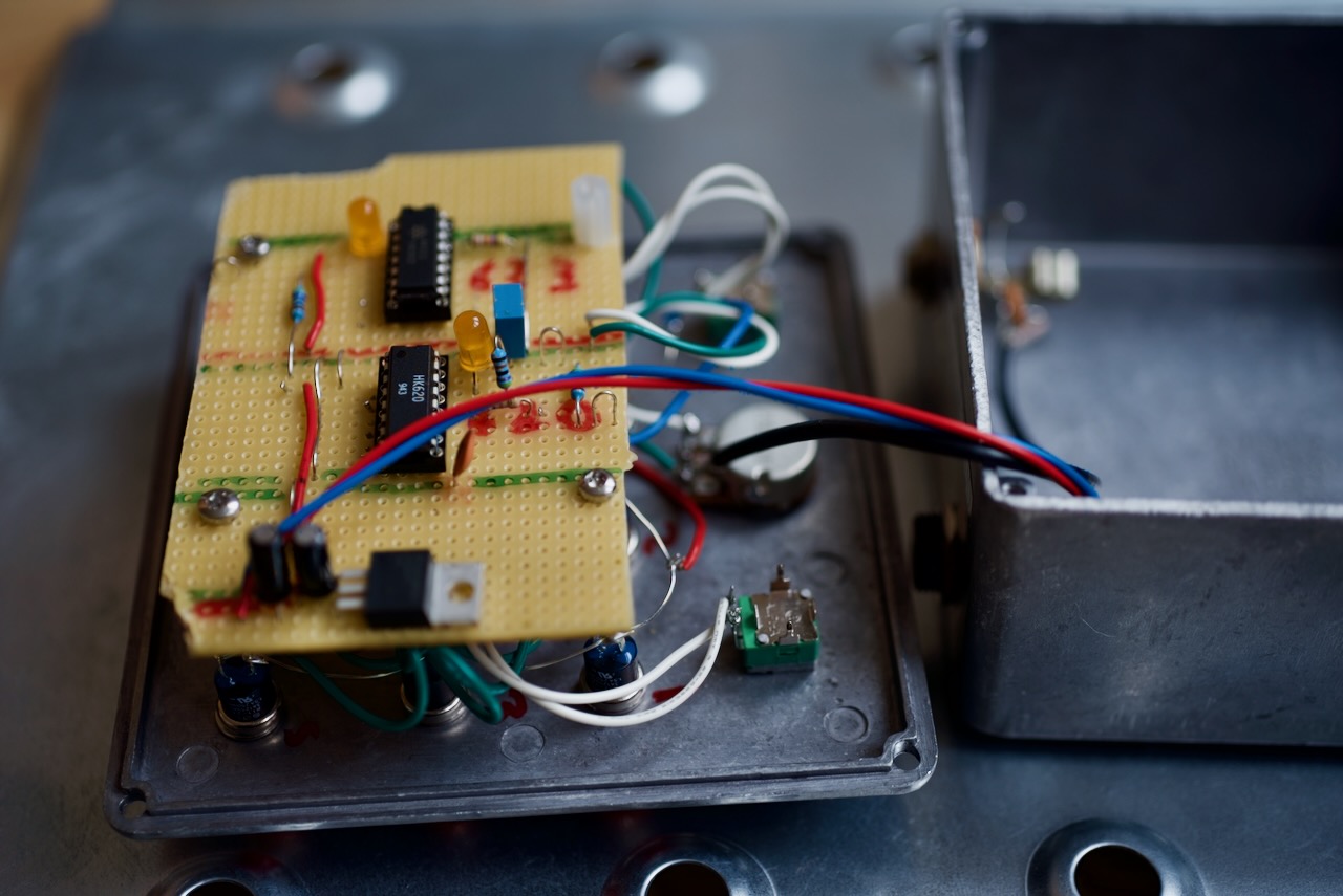
Inspecting the rest of the circuitry, the only other problem I could find was a shattered transistor on one of the gate drive boards, which looked like it had been mechanically damaged while taking the unit apart.
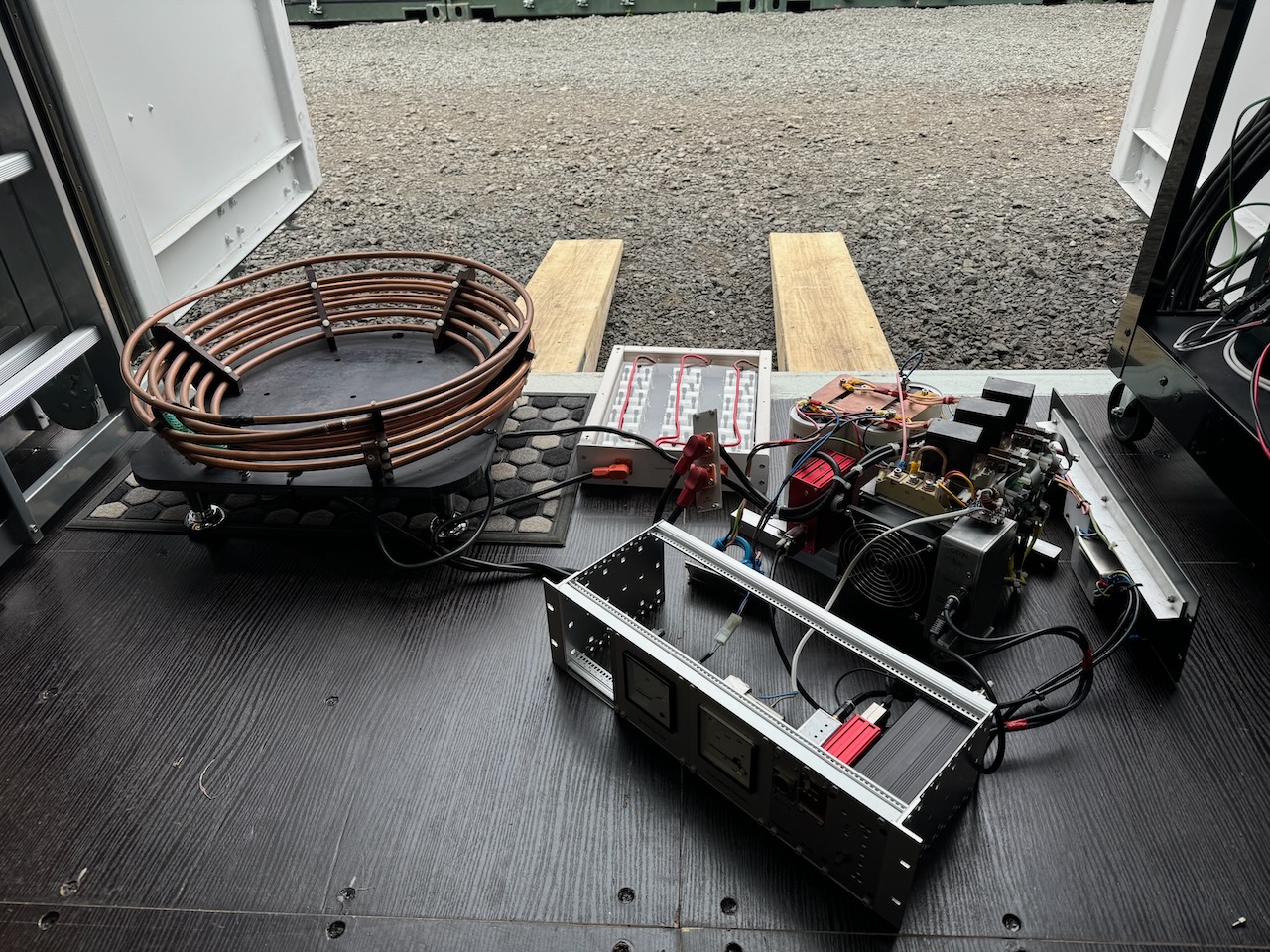
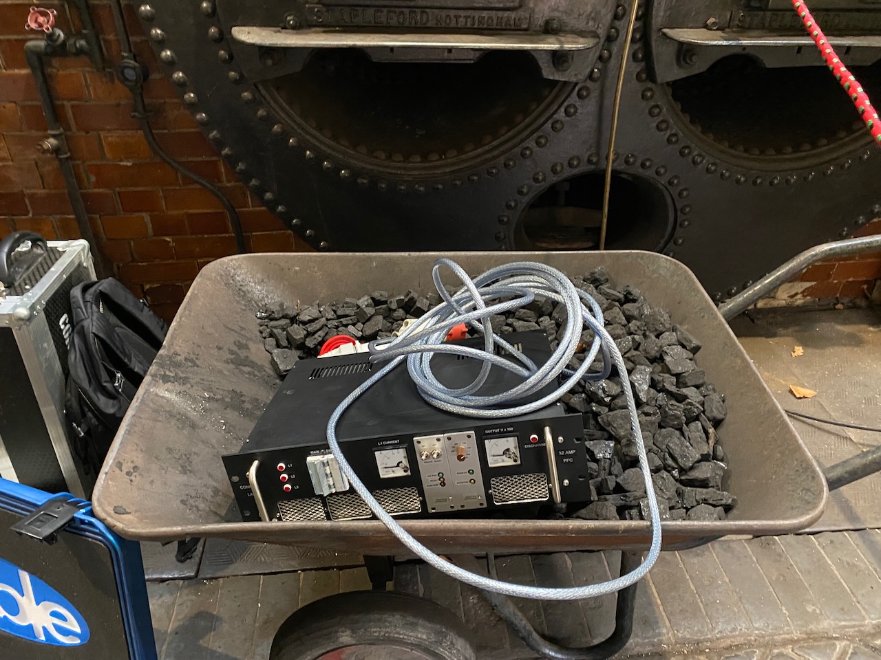
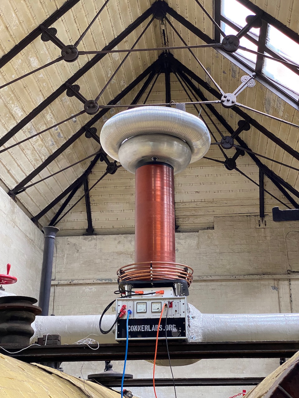
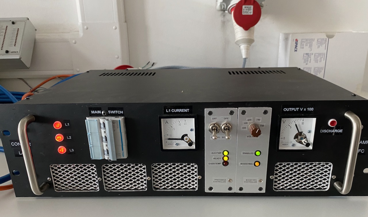
After a few days’ wait for Farnell to deliver a replacement, I headed to the container and set up all the parts of Odin minus the secondary coil for a dummy load test.
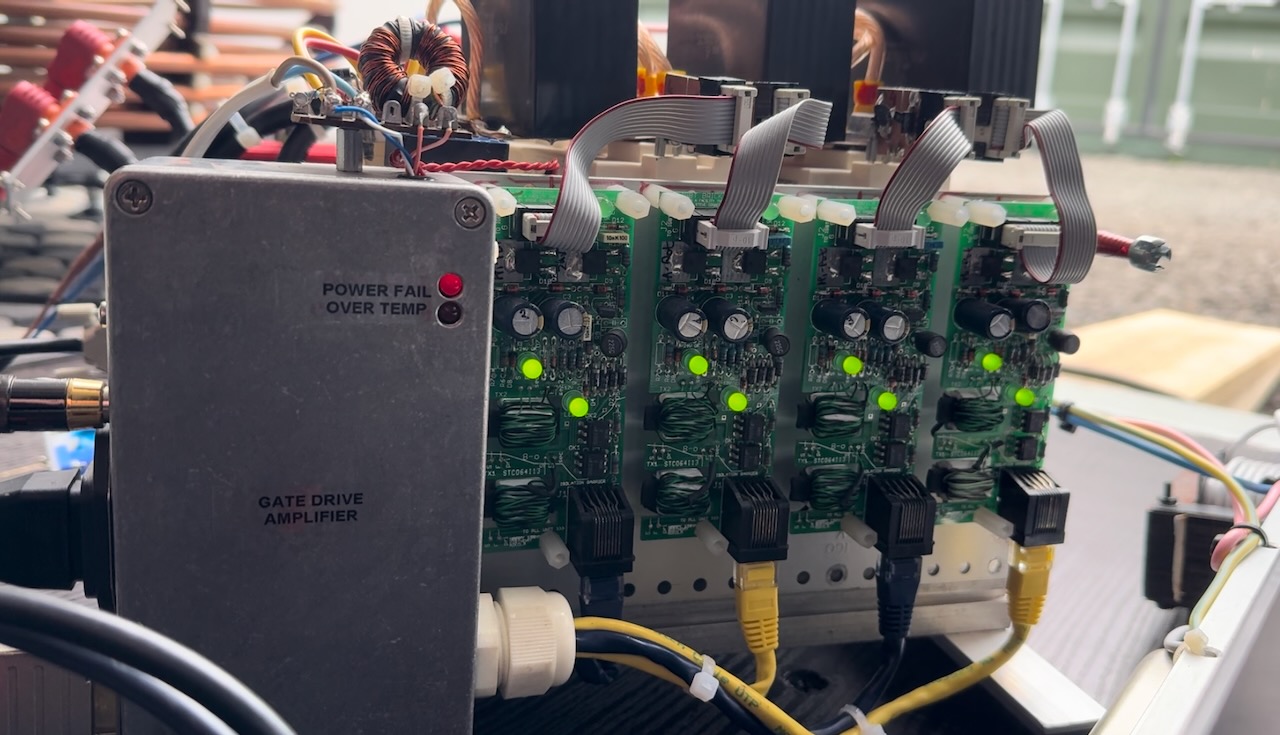
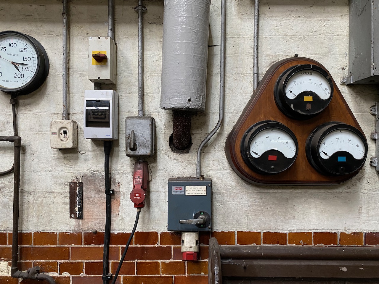
Unfortunately something wasn’t right, the primary current was well below what it should be, and the “Power Fail” LED lit up every time the fire button was pressed.
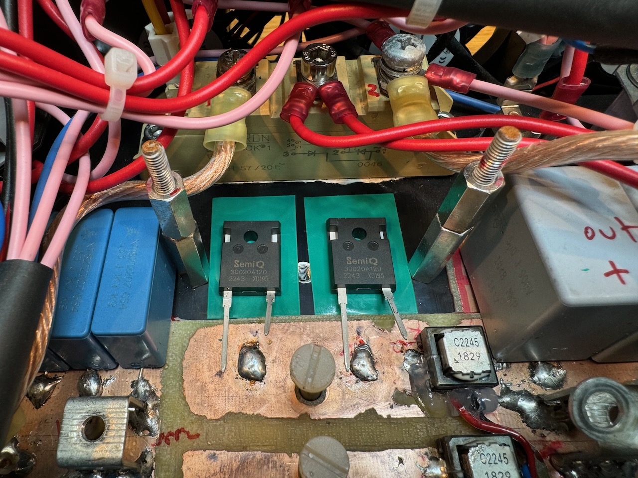
Suspecting a wounded IGBT brick that was drawing a lot of gate current and overloading its gate driver, I took the bridge apart and tested everything, but the IGBTs seemed fine! All the resistance and diode tests checked out, and a 9v battery turned them on and off happily.

Using Banggood’s finest thermal imaging camera (80 x 60 pixels resolution!) I could see that something on one of the gate drive boards was getting exceptionally hot.
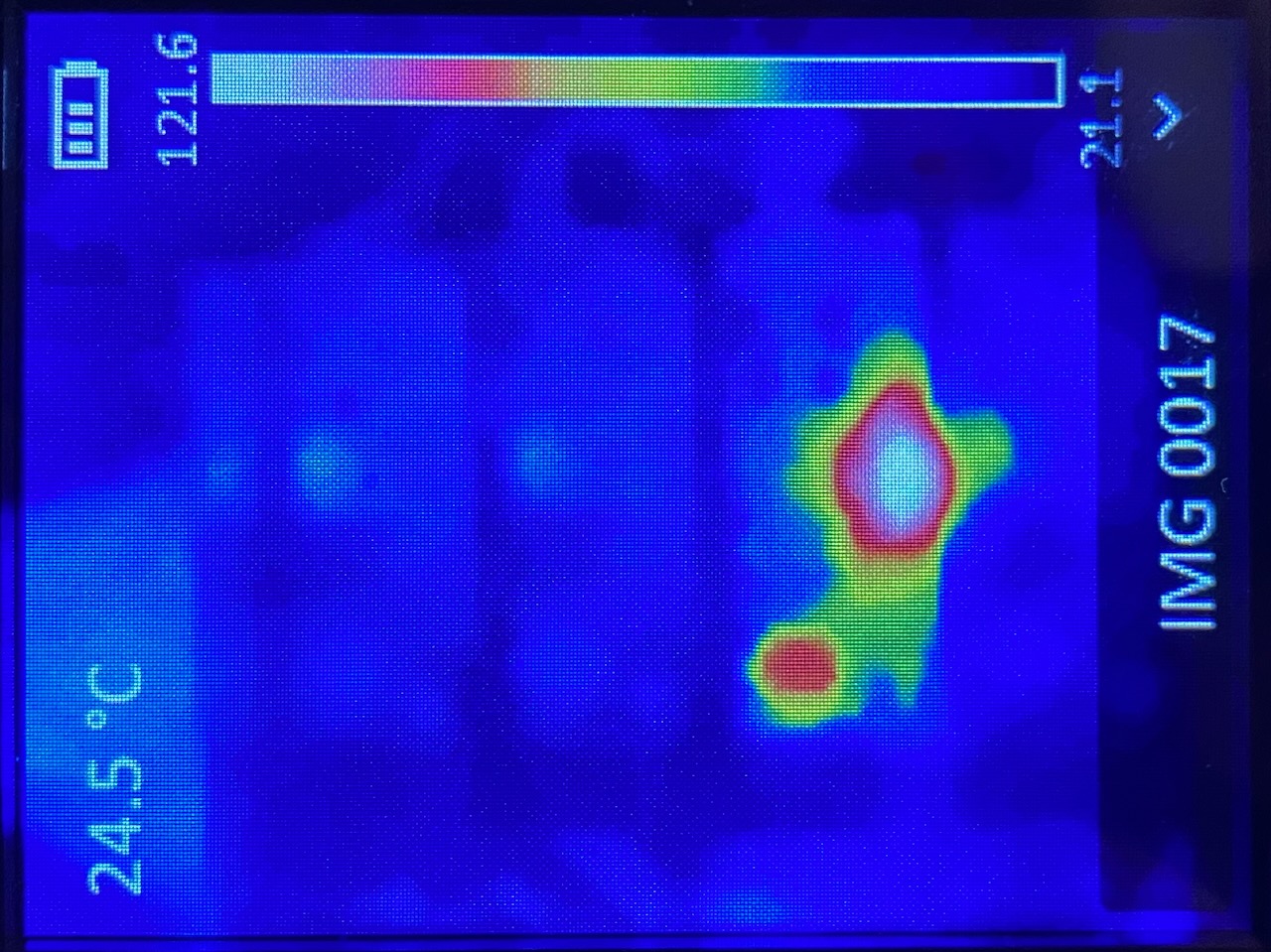
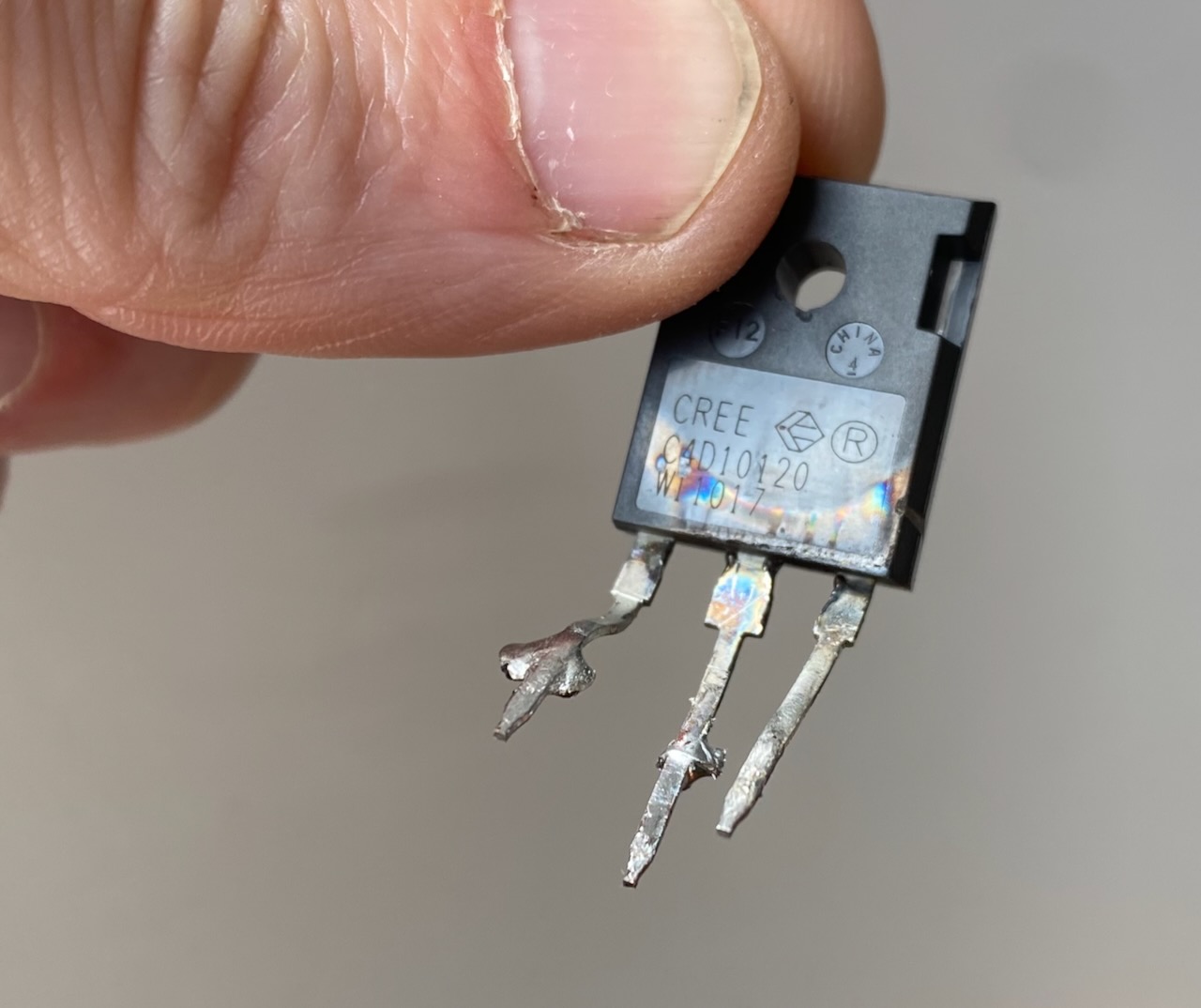
It turned out to be a shorted diode in the gate drive board’s power supply that was causing the voltage to sag horribly and trigger the undervoltage lockout. UVLO is really important in this application where we are driving IGBTs well over their rated current. Trying to pass the full current with insufficient gate voltage will result in a big bang. Luckily the UVLO did its job today and there was no bang.
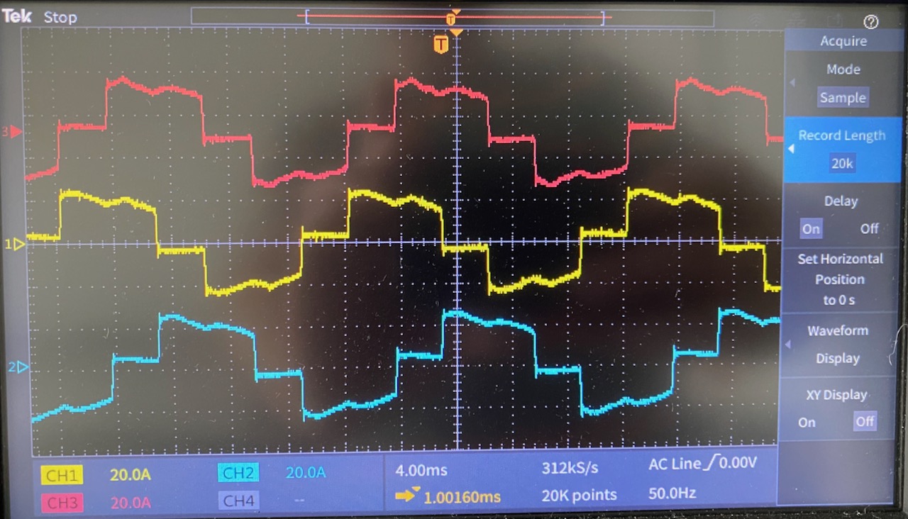
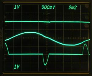
With the diode replaced, the Power Fail light went out and the gate waveform looked “just perfect” as Allen Millyard would say.
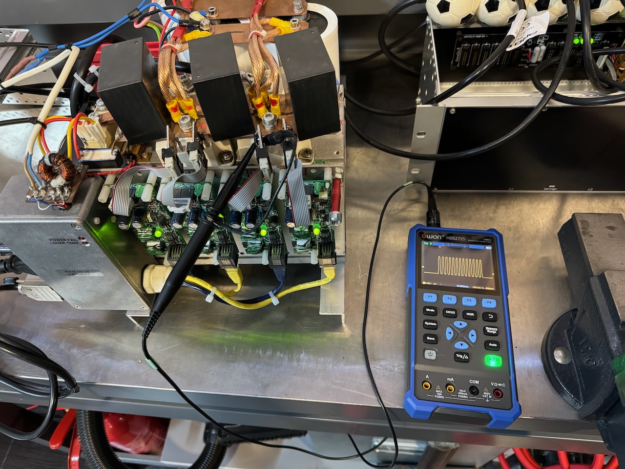
This looked encouraging so I put some DC bus voltage to it and the full 1250 amps of primary current were achieved with no obvious issues.
(These posts are a bit behind of events, I’ve since taken Odin to Gaussfest 2024 and everything performed fine.)


