Writing this, I was inspired by an article by Jim Williams called “Max Wien, Bill Hewlett and a rainy Sunday afternoon”, which documents his investigation of the Wien bridge oscillator and how to lower its distortion.
1. I’m a fan of Jim Williams, and his crazy cartoons and application notes with names like “Switching Regulators for Poets”.
2. My prototype Blameless power amp was getting good enough that I needed a really low distortion oscillator to test it. Surprisingly, even my 24-bit home studio gear wasn’t good enough: sigma-delta converters generate a lot of ultrasonic noise that inflates the THD figure. And my Twintrak Pro mainly generates smoke.
3. I could not find a Tektronix SG505 or SG5010 for sale at a reasonable price.
4. Neither could I be bothered building the oscillator section of Bob Cordell’s DIY THD analyzer.
5. A search of my kitchen junk cupboard yielded a RA53 thermistor.
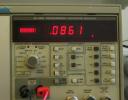
6. A Google search of the part number revealed that it’s the magic ingredient for making a really good Wien bridge oscillator. So, using the RA53 and a NE5532 op-amp, it only took about an hour to make an oscillator that ran off a couple of 9v batteries, and measured about 0.007% THD at 10kHz on my analyser. (The remaining THD is probably a combination of ignoring Williams’ Law, thermal modulation in the thermistor, and the dirty mains in our lab.)
7. So, this morning I tested the Blameless using my new low-distortion oscillator. It was clean enough that I could see the “gm-doubling” distortion described by Self when the amp was biased too hot: the first time this effect has ever been reproduced at Conner Labs. 🙂 Optimal bias seemed to be about 8-9mV per side, though it wasn’t clear whether this was just cancelling the oscillator distortion, and the true minimum might be at a higher idle current.
8. The results were really good. The 10kHz, 100W, 4 ohm THD came out around 0.01%. I used the 80kHz low-pass filter, but from inspection of the residual, it wasn’t filtering much: mostly the 200kHz switching noise that our mains is ridden with. At 10kHz, 2W, it was about 0.007%.
9. I cranked it up to 140W and let it get really hot. This only caused about 1mV change in bias, and checking again at 2W, the THD reading and residual looked pretty much the same. Then I rigged up a fan to cool it down again, and that didn’t make much difference either. Yay for those ThermalTrak transistors, then.
10. Renting an Audio Precision test set costs about £600/month for the entry-level one. So, I decided to call it quits at this point. The Blameless is now complete, and it just needs another channel, DC offset protection, and a box. I shall publish the schematics soon.
11. When Jim Williams was done with his oscillators, he cooked some hot dogs. I am ashamed to admit that I ate a McDonalds.
12. Now I am obsessed with trying to make a digitally controlled version of Cordell’s oscillator. 🙂


