Compensating the PG508

I got it to work and amplify, but the loop gain left a lot to be desired, so I decided to start over on the compensation. I also hooked up an unregulated power supply and a different output stage, partly because I wanted to see how the PSRR was doing, and partly because I wanted to reassemble the Ice Block with its original driver board.

It survived πŸ™‚

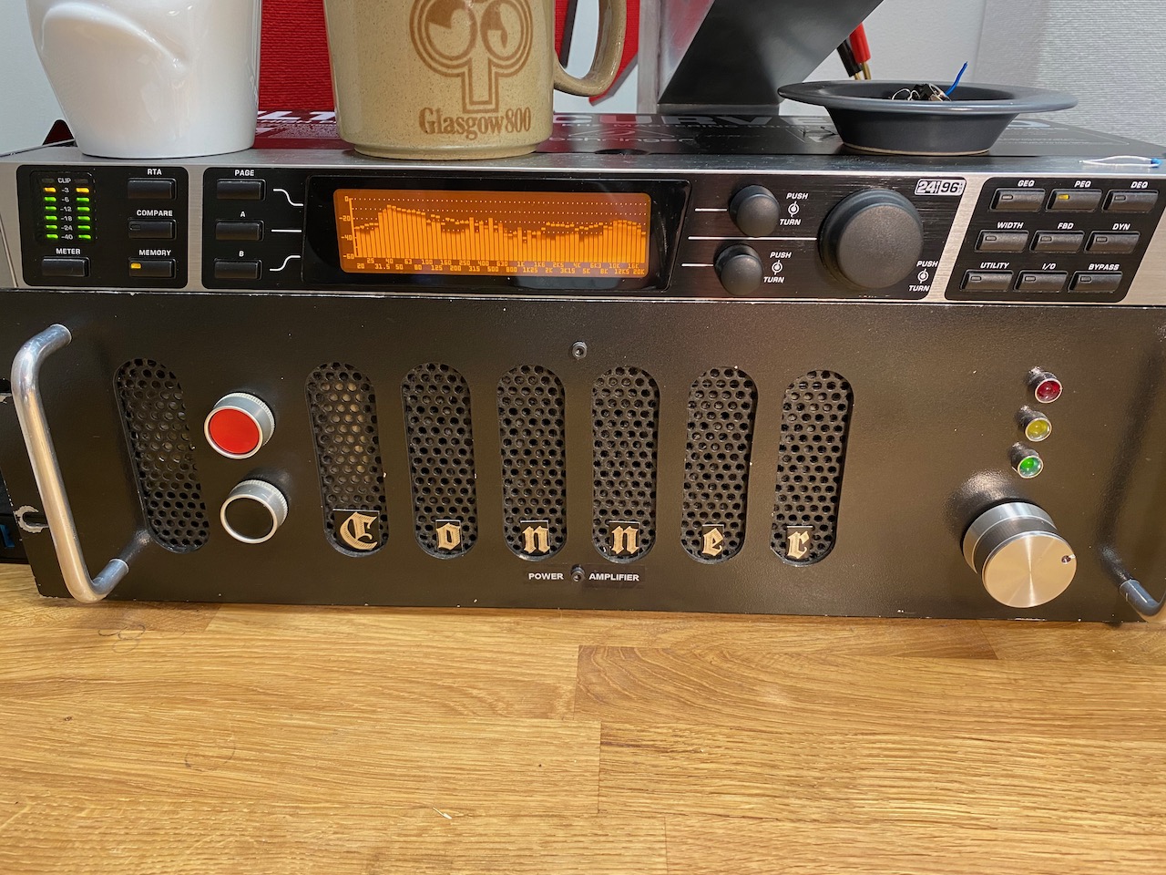
Now, you should never anthropomorphise amplifiers, they hate it! I swear that this one “wants” to blast electronic music from the 90s at high volume though. πŸ™‚

Found this in my junk pile, retro or what πŸ™‚

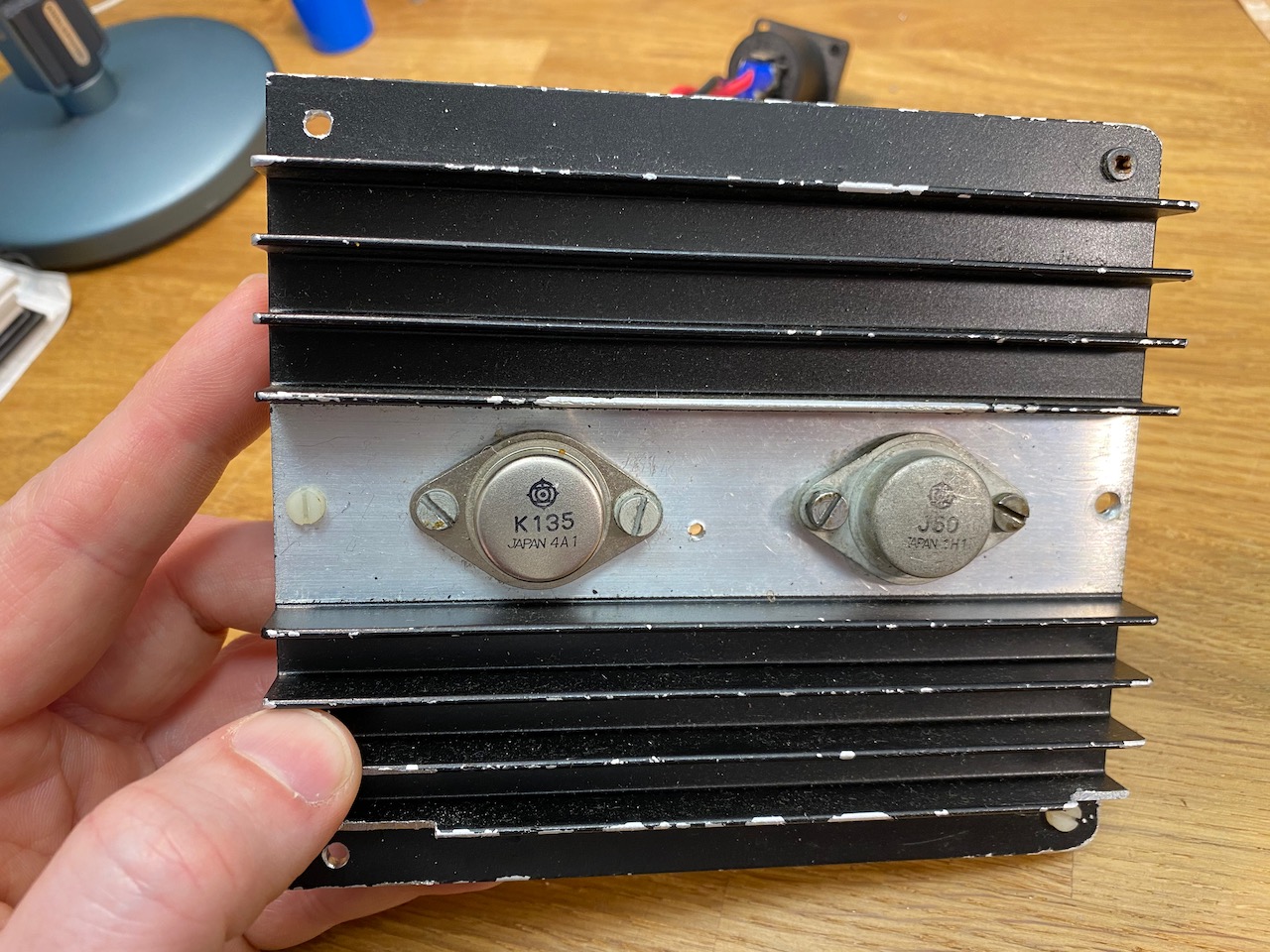
Having given the Ice Block its output stage back, I had to find another one for my experiments. A search of the junk pile yielded the remains of a Maplin 100W MOSFET amp kit. I’d have preferred to try BJTs, but the PG508 prototype was already set up to work with lateral MOSFETs.

Put it together and what have you got?

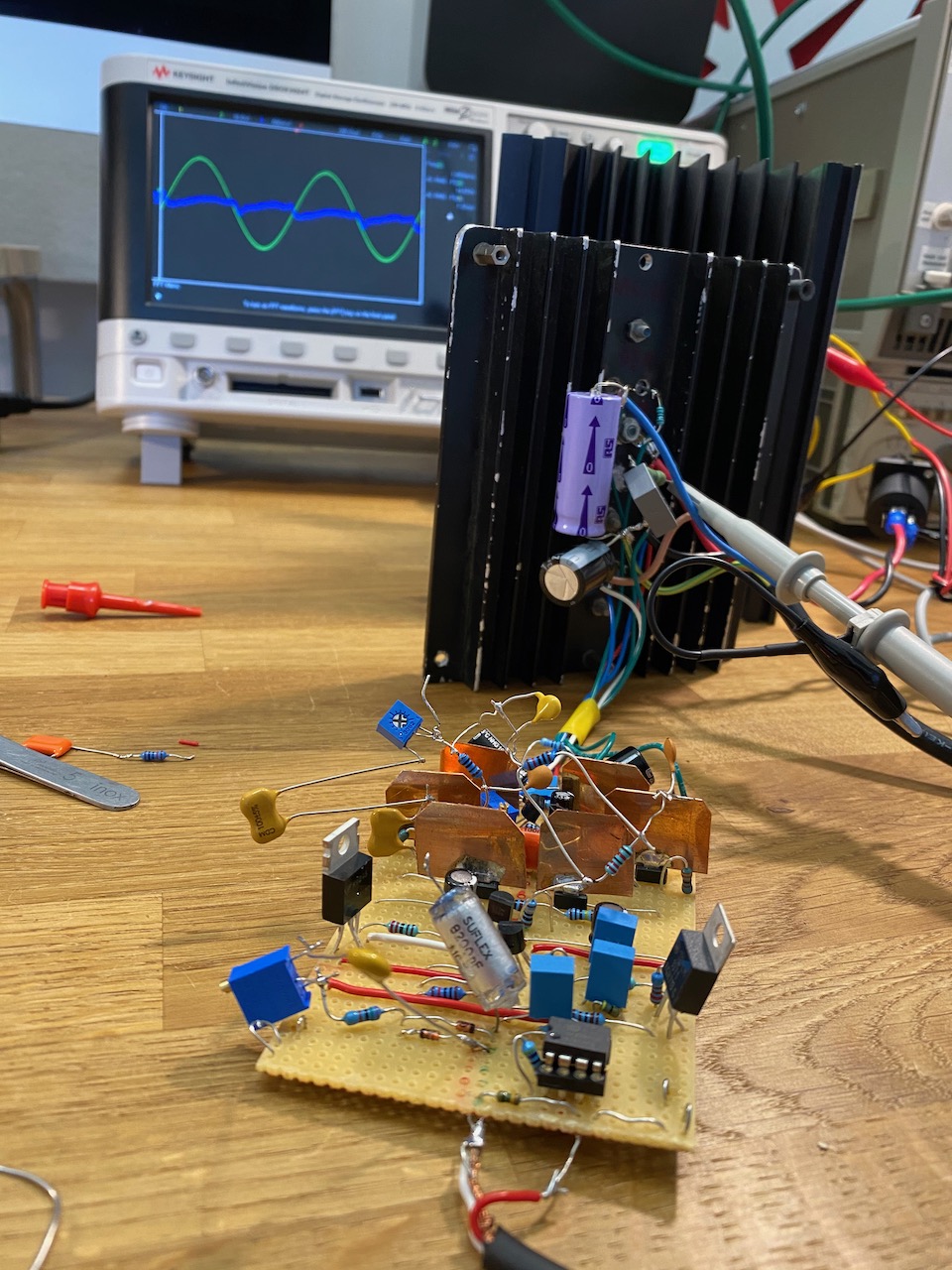
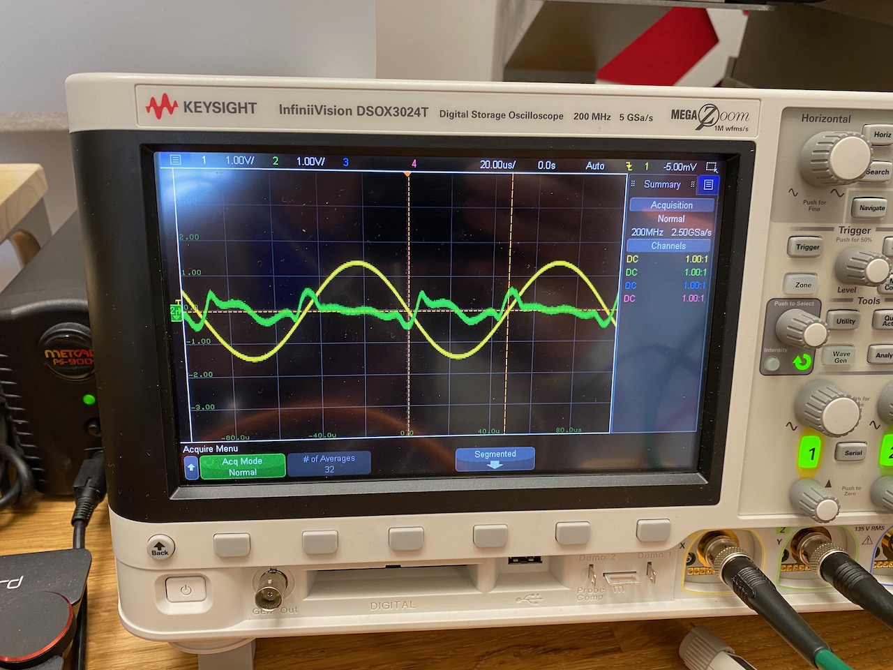
I tried the time-honoured method of soldering RC networks in random places, or maybe places that seemed to make a difference when touched with a damp finger. πŸ™‚ This improved it somewhat, but it still wasn’t doing a great job of correcting the output stage’s copious (and vintage correct!) crossover distortion.

Cordell to the rescue!

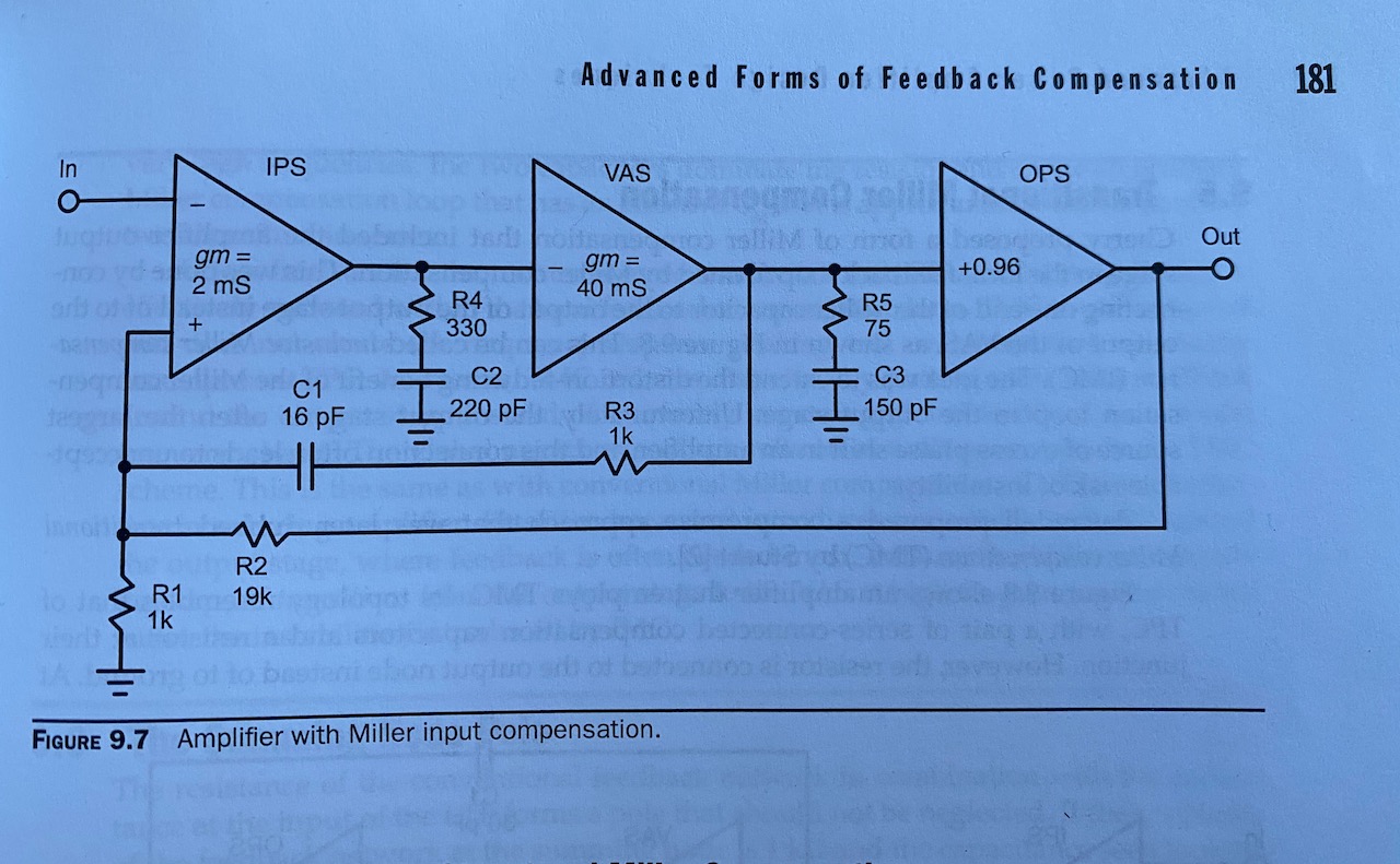
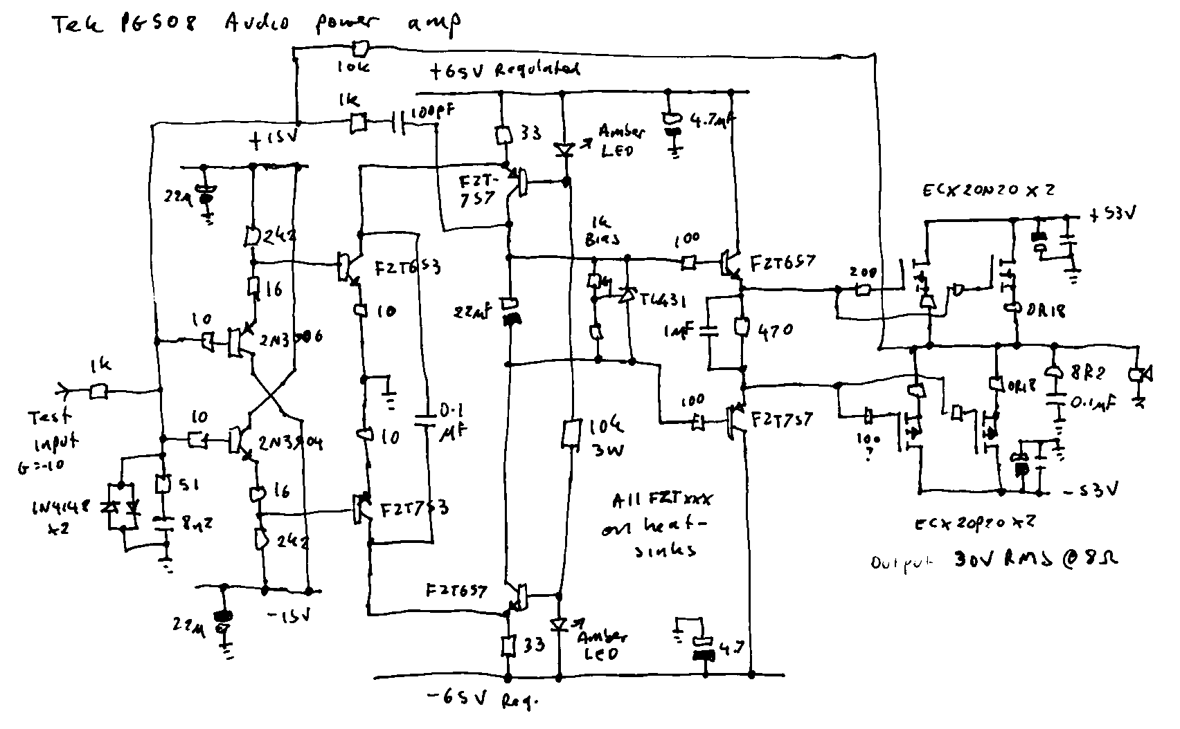
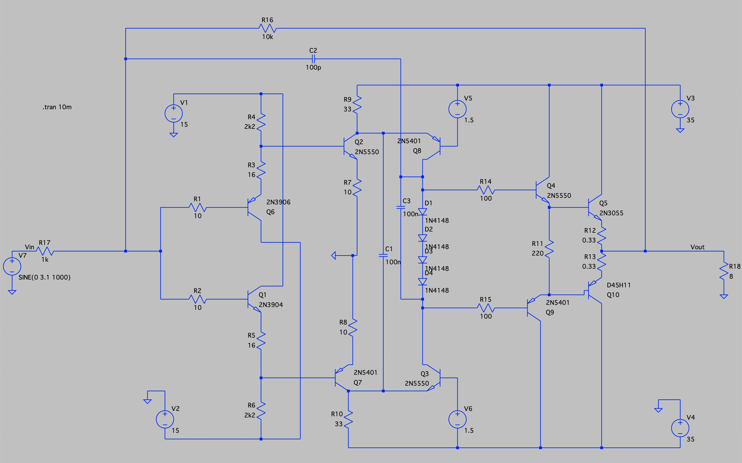
I eventually cracked Bob Cordell’s “Designing Audio Power Amplifiers” and spent an afternoon pondering Chapter 9, “Advanced Forms of Feedback Compensation”. It struck me that the PG508 topology is very similar to figure 9.7, except that the input stage doesn’t exist as such: the feedback node is the VAS input.

It also struck me that I’d already ended up with RC networks in the places shown in fig. 9.7 by trial and error, just with completely different values. R4 and C2 were in the original Tektronix PG508, and R5 C3, R3 C1 were my additions. So the obvious course of action was to change them to the values suggested by Cordell and see what happened.

Initial results weren’t great: it oscillated at 20MHz, but this was squelched by reducing R4 to 51 ohms. Having done this, performance was excellent: the 16pF C1 gave the extra loop gain I was looking for. I’d started out with 100pF here as that’s the value used in a Douglas Self Blameless amp. The Blameless input stage typically has 5-10x the gm of the PG508’s non-existent IPS, though. So funnily enough C1 needs to be 5-10x smaller to get comparable loop gain.

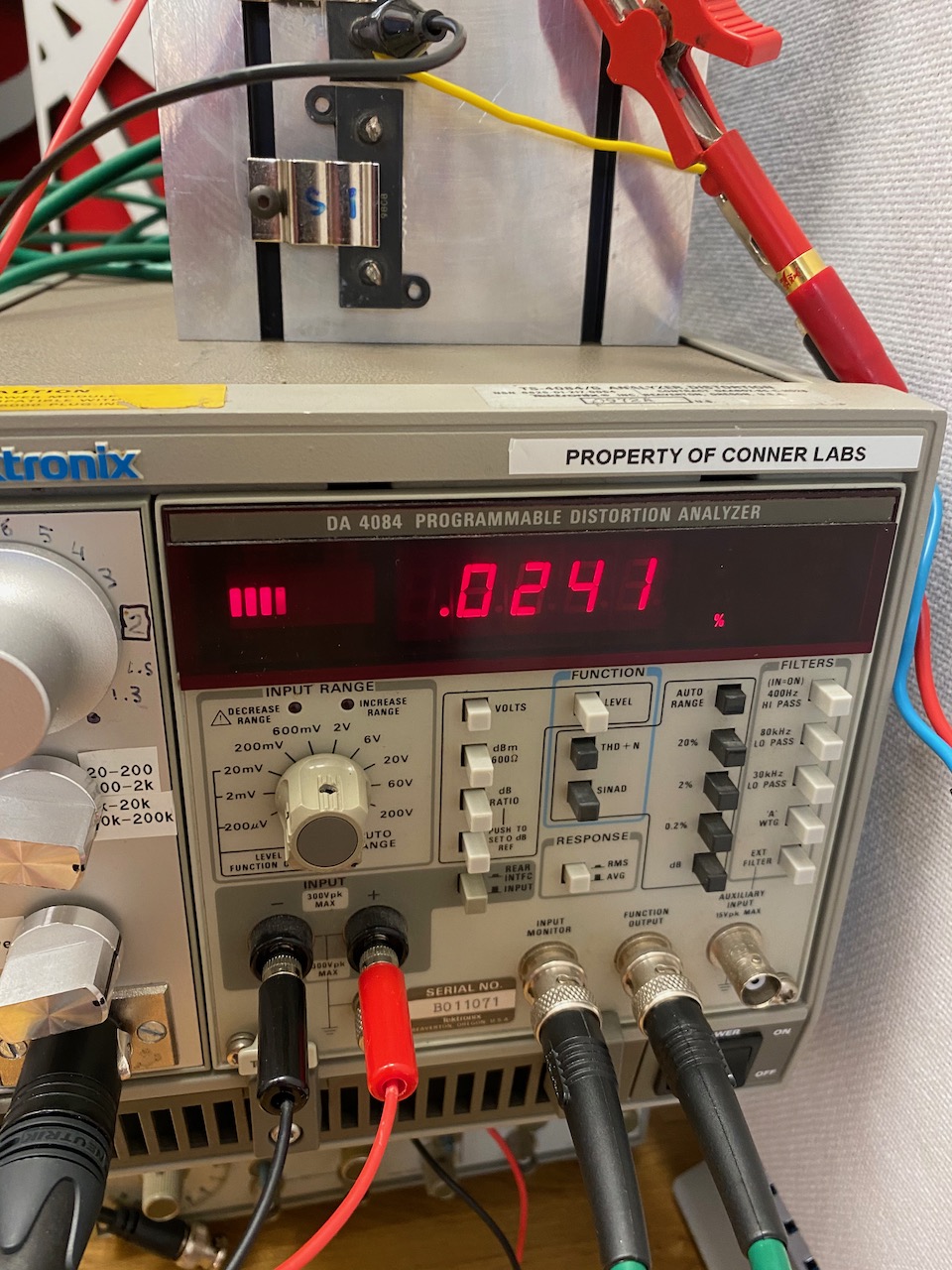
With these modifications the measured performance was 0.03% THD at full power at 10kHz, and 0.00something at 1kHz. The 10kHz figure seems high, but it’s now in the ballpark for a well functioning driver doing its best with a vintage MOSFET output stage. (Cordell’s AES paper quoted 0.02% at 10kHz with the Hawksford error correction turned off.)

Note that this THD figure is no better than I got with the old compensation and the Ice Block output stage. This just means that the Ice Block output stage must have about 3-5x less distortion than the single 2SK135/2SJ50 pair used here.

Slew rate was also improved, and stability with a capacitive load was just about acceptable: with 0.1uF slapped on the output it showed a few cycles of damped ringing but didn’t oscillate.

The circuit at the end of a hard day of soldering capacitors at random (and trying to find a LM317 or 7912 : ) )

I also took the opportunity to test out the opamp front end inspired by the Quad 405 and Cordell Super Gain Clone. I used an OPA2604 as it was the best opamp I had around. This works very nicely: it reduces the DC offset to 2mV, undoes the phase inversion inherent in the PG508 circuit, and increases the overall gain from 10 to 50.

Note that the opamp must be a FET input type because of the high impedance of the DC feedback path. Also, as the circuit has 2 LF time constants (the 1M/1u and the 47k/2u) with feedback around them, it functions as a 2nd order active high pass filter. It rolls off at 12dB/octave and can resonate if the time constants are too close together.

I basically copied this part from the Quad 405, so it must have done the same thing. I guess it was desirable to have a good rumble filter here in the days of vinyl. Arguably it still is in the era of small vented speaker cabinets and dubstep. πŸ™‚

PG508 audio amp part 2

I was so excited (honestly 8) ) about the idea of a PG508-based audio amp that I decided to try building it in real life.

Fig.1: This is what I made

I first tested the driver circuit with +-15V supplies, no output stage and pure dominant pole compensation. It oscillated happily at 6MHz, and to get it stable I had to go back to the original PG508 lag compensation network (the 51 ohm and 8n2) The back-to-back diodes helped the clipping behaviour: without them you can reverse bias the cascode transistors and burn out the LEDs if you really overdrive it.

Fig.2: DIY heatsinks for SOT-223 transistors

In the interest of getting something working quickly, I hooked it up to the output stage and power supplies of my ancient and long-suffering Ice Block amp, which conveniently happened to be partly dismantled with one driver board missing. It provides regulated +-65V and +-15V rails in addition to the main +-53V, so no worries about PSRR for the time being.

Fig.3: The heatsinks weren’t quite big enough.

To achieve stability with the Ice Block’s hefty lateral MOSFET output stage in the loop (2 pairs of double die Exicon FETs) I had to use both the original PG508 compensation and dominant pole compensation with an extra zero (the 1k and 100pF).

I think it’s a bit temperamental because there are 3 transistor stages in the loop enclosed by the dominant pole capacitor. The Douglas Self Blameless only has 2, and my previous attempts at adding a third stage to that (cascode connection of Cdom) also caused oscillations at a few MHz.

As with any half decent solid-state amp, THD+N was at the limit of my measurement system at 1kHz, and dominated by noise. I had to go to full power at 10kHz to see a meaningful distortion residual.

Fig.4: THD result at 10kHz, 100W into 9.4 ohms
Fig.5: Distortion residual at 100W, 10kHz. (Fancy scope on loan from work πŸ™‚ )

The distortion appears to be what Douglas Self called “gm-doubling”: in a push-pull circuit the gain is higher when both halves of the circuit are contributing, than when one half is cut off. And in the residual we see small lumps corresponding to increased gain around the zero crossings. I’m not entirely sure what part of the circuit is causing it. It may be the output stage, as that’s the usual culprit. It looks like it wants less bias, but the bias pot won’t go down any further. (Got to replace that TL431 with a TLV431)

I also tested the full power bandwidth, and it happily delivers 100W to 100kHz and beyond. I didn’t push it beyond 130kHz for fear of burning out the Zobel network.

A reading of 0.025% at 100W and 10kHz, with no filters engaged, is not to be sneezed at. I’d be perfectly happy with it, except the other un-hacked channel of the Ice Block does 0.009%! The PG508 circuit has some way to go before it can beat the original Alexander CFB.

While I had the equipment out, I also tried measuring distortion with a LF411 in place of the SSM2131 in the Alexander circuit. It made no noticeable difference at any power level, even though I’d persuaded myself that the LF411 sounded bad…

Tek PG508 output stage as audio amp

I recently came across this gem in the X Chapters supplement to the Art of Electronics 3rd edition. (Not reproducing here because of copyright. You need to buy the book anyway, it’s brilliant πŸ˜‰ )

Fig. 1: Tek PG508 nifty folded cascode with audio power amp output stage duct taped on.

Of course my first idea was to convert it to dominant pole compensation (C2) and bodge a standard audio power amp output stage onto it.

This worked very nicely in simulation, so the next step was to slap on an opamp front end ala Quad 405 or Cordell Super Gain Clone.

Fig.2: opamp adds voltage gain and functions as DC servo

The resulting circuit should give a lot of bang for the buck when used with a good quality FET input opamp. I expect it to outperform the Alexander CFB design in areas that matter, like HF THD, PSRR, playing well with the standard Bailey current limiter circuit, and not depending on an obsolete opamp or catching fire when overdriven.

This is a voltage feedback design, not current feedback, and won’t beat the Alexander’s slew rate without running the transistors at crazy idle currents. Besides being CFB, the Alexander driver circuit operated in Class AB and could call on arbitrary amounts of current when slewing was required. The price it paid for this was catching fire when overdriven πŸ™‚ and also crossover distortion generated in the opamp’s output stage, which is very audible if you use any other opamp than the original SSM2131. (And kind of audible even with the SSM2131 imo…)

So overall I am happy with this set of compromises and looking forward to trying it out in real life.