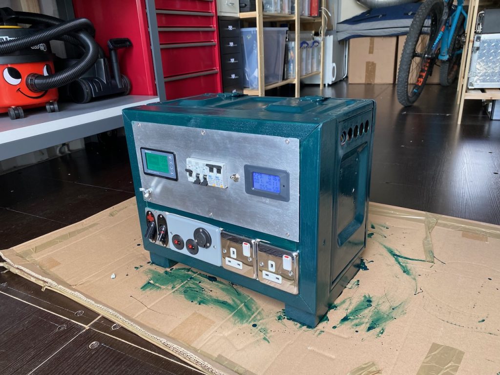
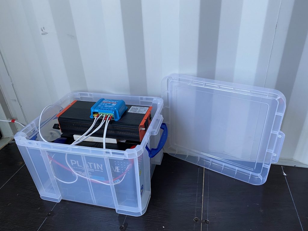
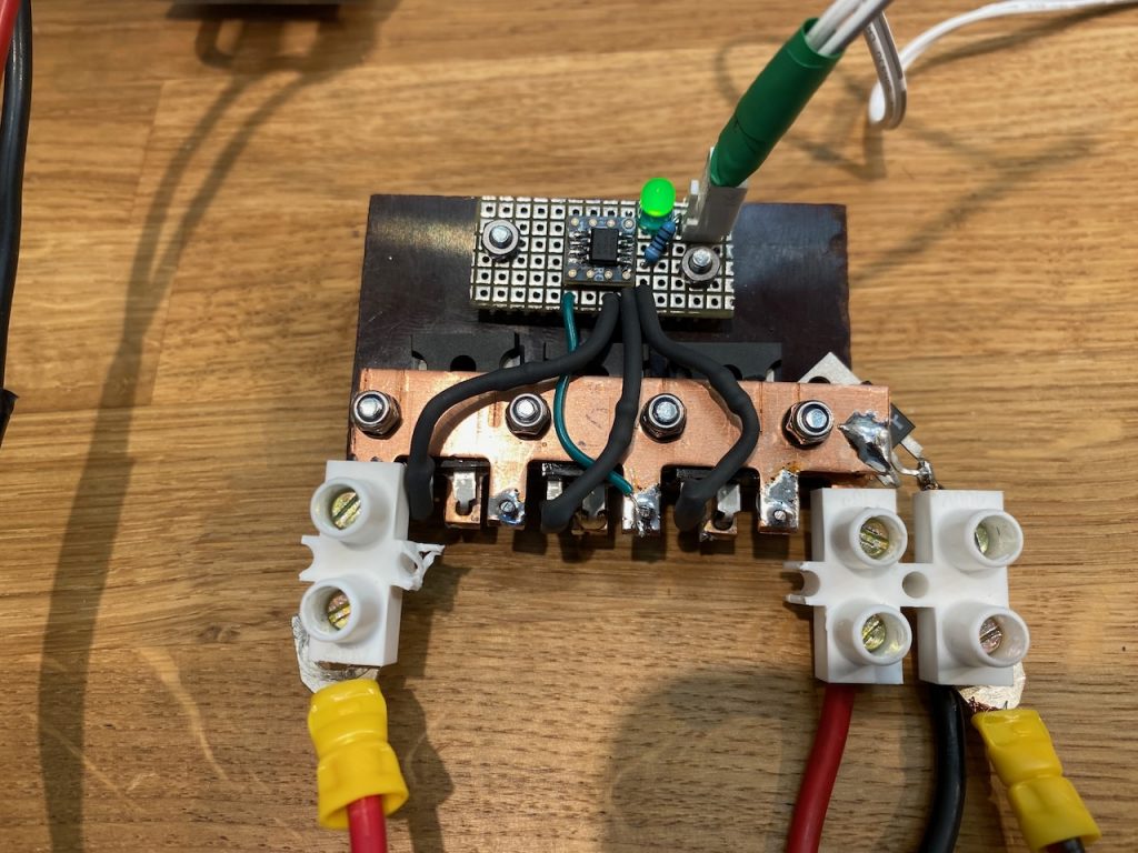
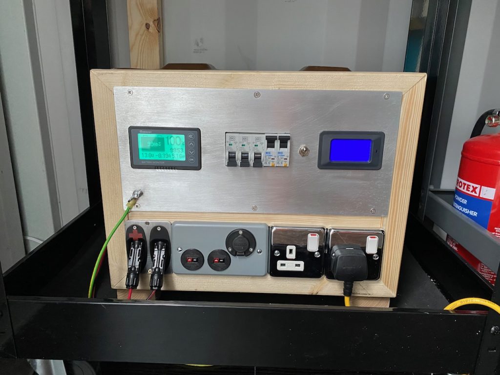
A gadget to charge the Power Tank off AC power.
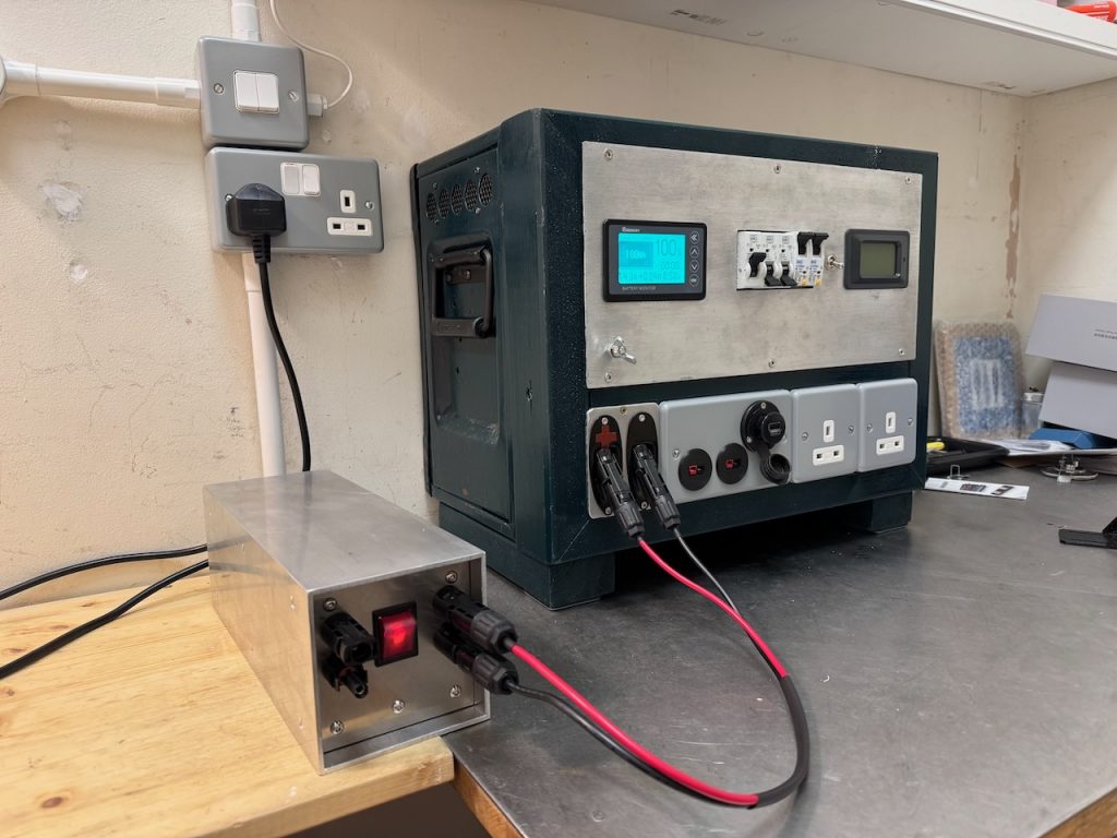
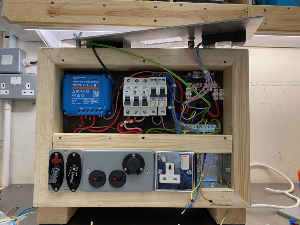
The Power Tank uses a Victron MPPT 75/15 for battery charging. I experimented with this and found that it would happily charge from a DC power supply connected to the PV input.
I tried several different bench power supplies and also 18V DeWalt cordless drill batteries, and all seemed to work fine. Victron specify that the DC input voltage has to be at least 5V above battery voltage for the charger to start, and then 1V greater for it to continue running, so in practice 24 or 48V DC would be a good input voltage for my 12V system.
I settled on a Meanwell HLG-240H-48A LED driver obtained cheaply on eBay, that supplies 48V DC at 5A.
This worked just fine plugged directly into the solar input, but I decided to complicate things by adding an automatic changeover between solar and AC charging when AC power was present. My first attempt was to use a couple of diodes to OR the solar and PSU inputs, but this didn’t work. The PSU would be dragged into current limit as soon as it was turned on, and the MPPT would then ramp its output voltage up and down searching for a max power point and never find it.
The key to a successful changeover turned out to be to disconnect the solar panels, wait 5-10 seconds for the input voltage to fall to zero and the MPPT to shut down, and then connect the power supply. I made a circuit to do this automatically depending on the presence of AC power.
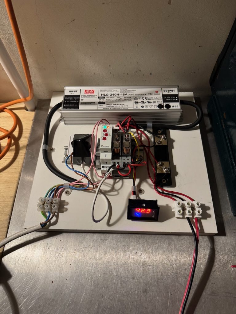
This junk box inspired design is based on a Europa ECMFT timer relay, and a Raspberry Pi 4 wall power supply that I’d previously cut the DC plug off for some reason. When AC power becomes present, the Raspberry Pi wall wart supplies 5V to a changeover relay, that disconnects the MPPT positive input from the solar panels and connects it to the 48V DC PSU, which is still turned off. After 10 seconds the timer relay switches the PSU on.
When AC power is lost the reverse happens. The 48V PSU turns off straight away, while the Raspberry Pi PSU keeps the changeover relay energised for a few seconds on its stored energy. This avoids the changeover relay having to break the 48V while current is flowing.
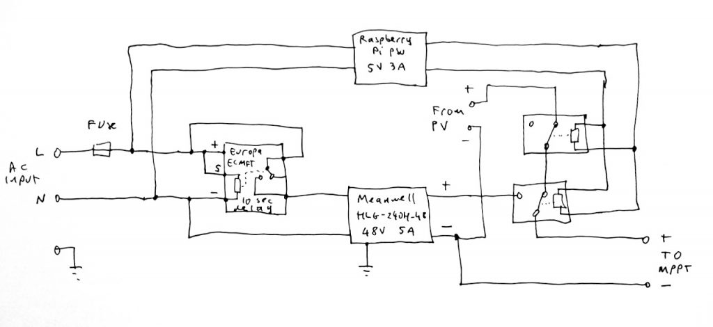
The main weakness of this circuit is that it uses a relay to break and make the DC output of the solar panels. Relay contacts typically have much reduced DC ratings compared to their AC rating, and most won’t even handle more than 30V DC.
This isn’t a huge problem, if there was lots of solar power available, why would I even be switching over to AC charging? Also my solar array is tiny and puts out less than 30V DC. However, I paid it some lip service by choosing a relay with a 30V DC rating, and putting two of them in series on the PV side. (What if the 2 relays don’t open at exactly the same time I hear you ask? Next question please…)
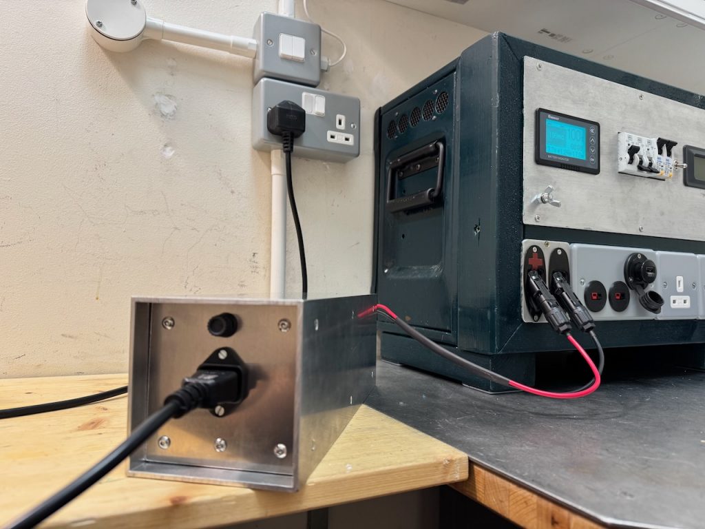
I tried a new enclosure construction technique for this, based on a piece of 4″ x 4″ aluminium box section. The ends are made of sheet aluminium and attached to the box section by aluminium angle. The HLG-240H-48A is screwed to the case with a generous amount of heatsink compound to help it lose heat by conduction, which it seems to manage OK.
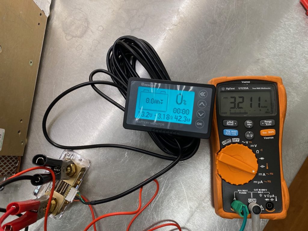
You might notice that the prototype had a digital voltage and current meter which is now gone. This cheap Chinese meter turned out to be basically a random number generator so I ditched it.
I think it looks great, but the wiring was a real pain and ended up very messy inside, because it all had to be done through the ends. I’m not sure I’d use this technique again unless the innards could be made to slide out as a single unit. That wasn’t possible in this case because of the power supply covered in heatsink grease.
