Tag: lfp

  • Fogstar LFP battery kit

    [In this episode of the Chinesium Mine, we dabble in the home energy storage market]

    I’ve loved playing with batteries ever since I was a kid, except for one horrible incident with a Burgess Safari Lite battery that put me off testing them with my tongue for life. More recently, electric vehicles and grid-scale battery energy storage have become A Thing, and all have standardised on the lithium iron phosphate battery (aka LiFePO4, LFP) so I thought I’d better get one for professional development. πŸ™‚

    Besides 100 different types of vape battery, Fogstar also sell large prismatic LFP cells and all kinds of accessories to build your own battery pack. I opted for their 12V DIY bundle with the EVE MB31 cells. Shipping 20kg of lithium ion batteries could have turned into a nightmare, but they were delivered with absolutely no hassles.

    A word of warning: Similar LFP cells can be found very cheaply on Ebay, Amazon, AliExpress, but buyer beware. There are a LOT of factory rejects and pulls from failed battery packs out there. I was reasonably confident that the Fogstar ones would be good.

    At only 3.2 volts each, the risk of another Burgess Safari Lite incident is minimal.
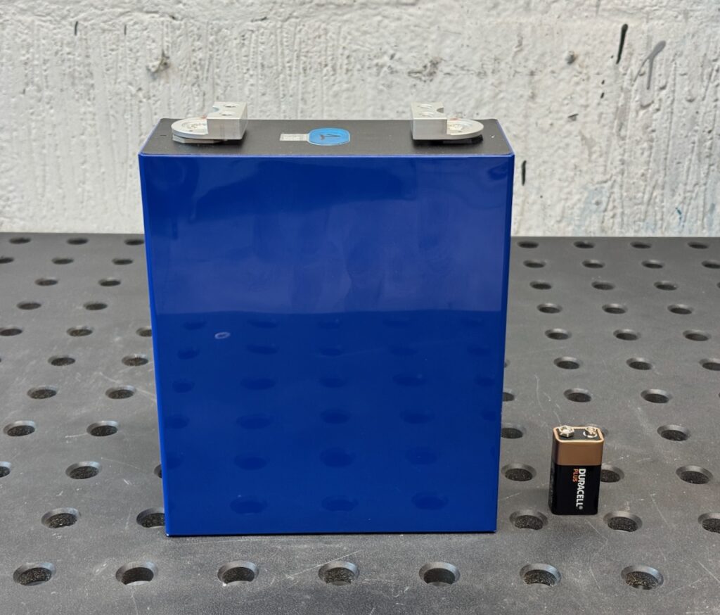
    It’s not all about voltage though. These have a capacity of 314 amp-hours and can deliver a lot of current.

    After doing some experiments with the raw cells [document in future and insert link] it was time to assemble the kit.

    Internet best practice says that the blue plastic wrap can’t be relied on for electrical insulation, and the manufacturers say that the cells need some pressure applied to their broad sides for optimal cycle life. The Fogstar kit covered both of these bases: FR4 glass fibre sheets were supplied to line the metal battery box, and foam pads to go between the cells. All sticky backed for Blue Peter nostalgia.
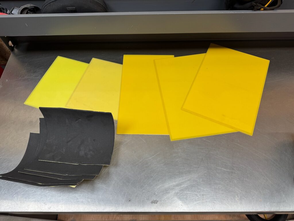
    EVE’s recommended compression force for their cells is 300kg! I’d be surprised if this metal plate and its 6 screws were up to that amount of force.
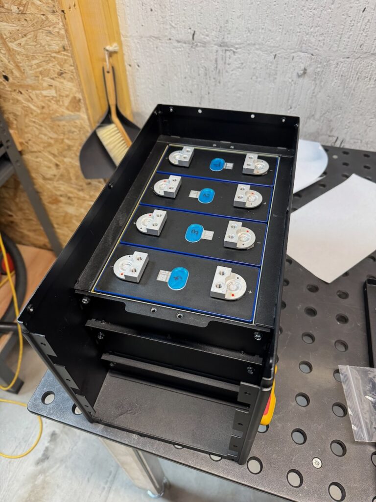
    Having said that, it did seem to squish the foam pads down a bit and clamp the cells in place firmly.
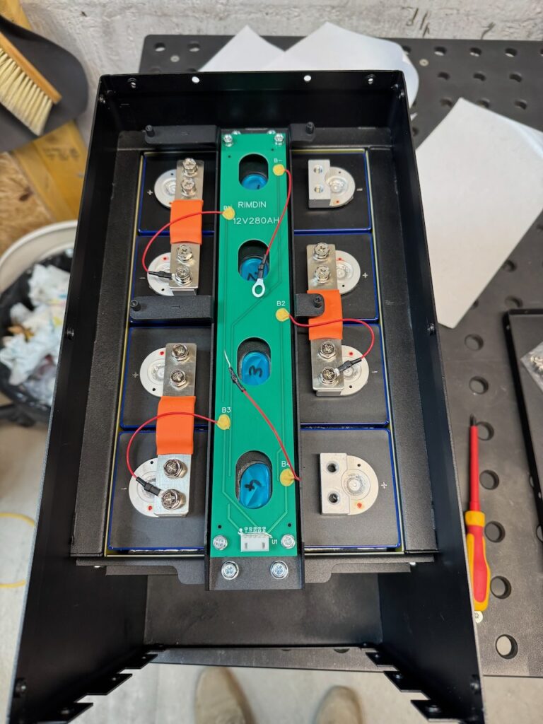
    The next step was to fit this clamping bar over the tops of the cells, complete with a sticky backed foam gasket on the underside. The main purpose of it seems to be to stop the cells falling out if the battery is turned upside down. (At this point it’s worth mentioning that LFP cells are completely sealed and won’t leak electrolyte unless something goes very badly wrong. I’ve seen them mounted in almost all orientations, but they probably work best with terminals up.)

    They are also rumoured to expand slightly as they charge. For my 12V stack, it probably works out to less than 1mm of expansion between empty and full. This is why the busbars supplied with the kit are flexible.
    LFP are similar to the other lithium ion chemistries, in that they have no ability to self balance, and no tolerance of overcharging or discharging to very low voltages. A single incident can turn your new cell into a “spicy pillow“. The cell bloats up with gas and is ruined for good.(though to be fair, LFP spicy pillows are much less likely to catch fire or explode than the other chemistries)

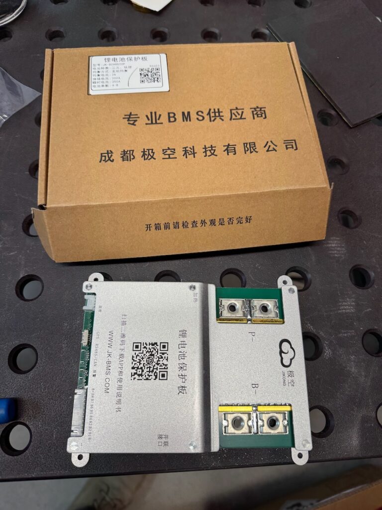
    To make sure the cells stay nice and prismatic, we need a BMS. The two most popular brands seem to be JK and JBD. My bundle included a JK 200 amp model with 2A active balancer.

    The mounting locations for the BMS needed a bit of gentle adjustment with a screwdriver, hammer and pliers. Out of the box, the BMS sat too high and the busbar connecting it to cell 1 negative put a lot of strain on the circuit board.
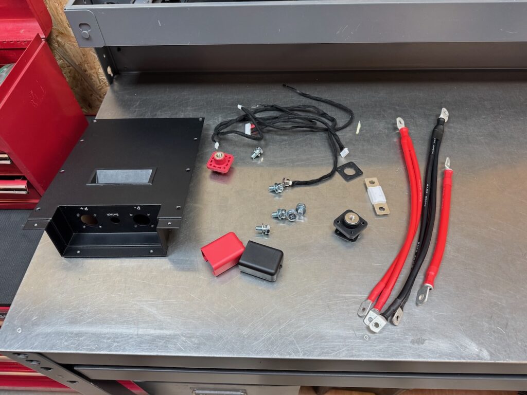
    I liked the terminals and cable/wire harnesses supplied with the kit.
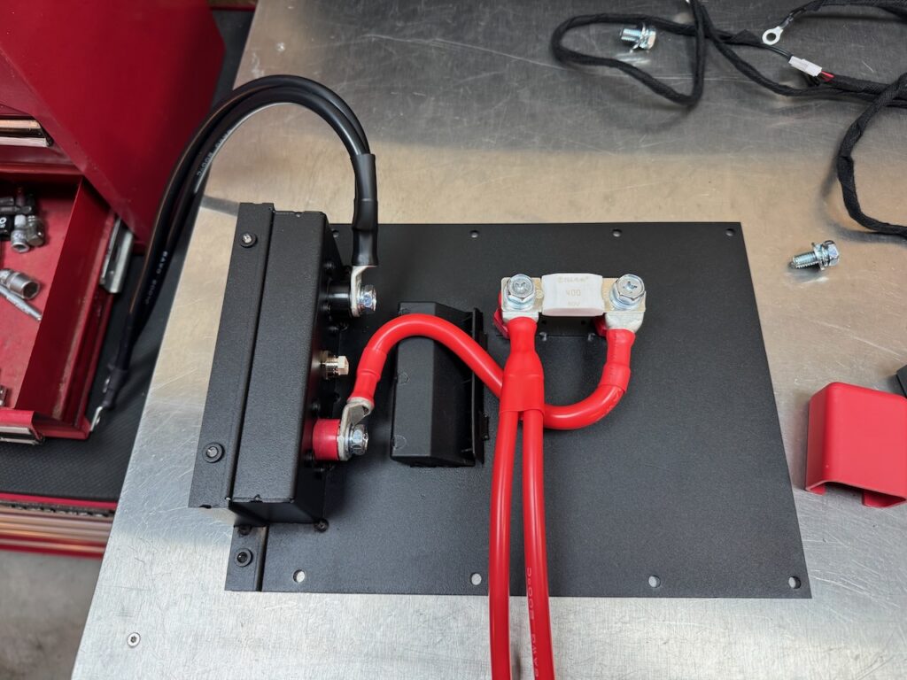
    They even included a 400 amp ceramic Mega fuse in case the BMS overcurrent protection fails. LFP might not be prone to catching fire themselves, but they most certainly can supply enough current to start a fire.
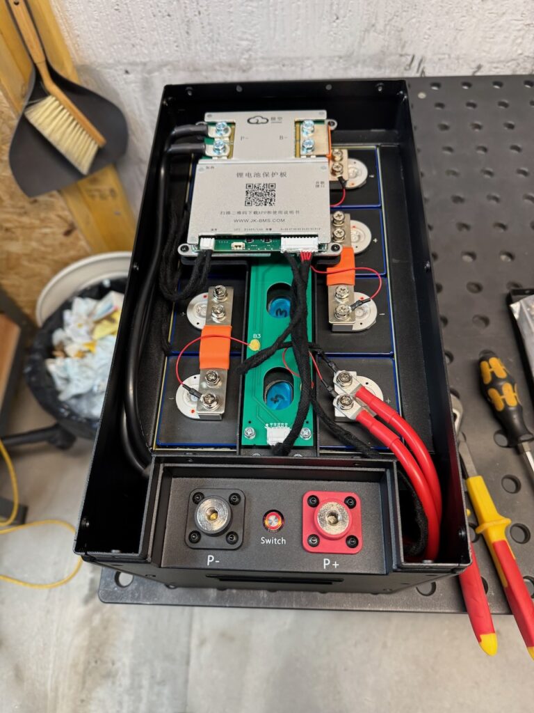
    Now came the hardest part of the build, did I mention that I’ve had enough of dodgy software to last me a lifetime? The BMS is configured and operated over Bluetooth by a smartphone app. It has two passwords, one to view status, and a different one to edit the settings. And nowhere do JK tell you what the default passwords are, or even that there are two. (For future reference, the view-only is 1234 and the settings password is 123456)

    Victron use a Bluetooth PIN on their gizmos and notify you right in their app that the default is 000000. But their equivalent LFP battery costs 4x what this one did…

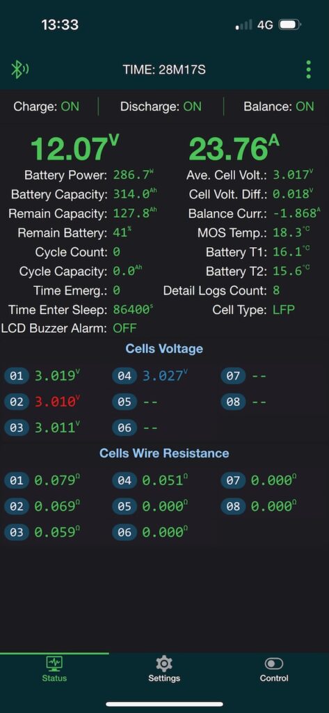
    Eventually I got into it and was able to select the LFP battery type and enter the actual capacity of 314Ah. To be fair, the JK BMS app seemed pretty good apart from the out-of-box experience with passwords.

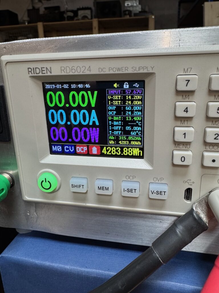
    Then the first charge could commence… I set the Riden RD6024 (another golden nugget of Chinesium) to 24A, 14.2V, and a charge termination current of 5A.
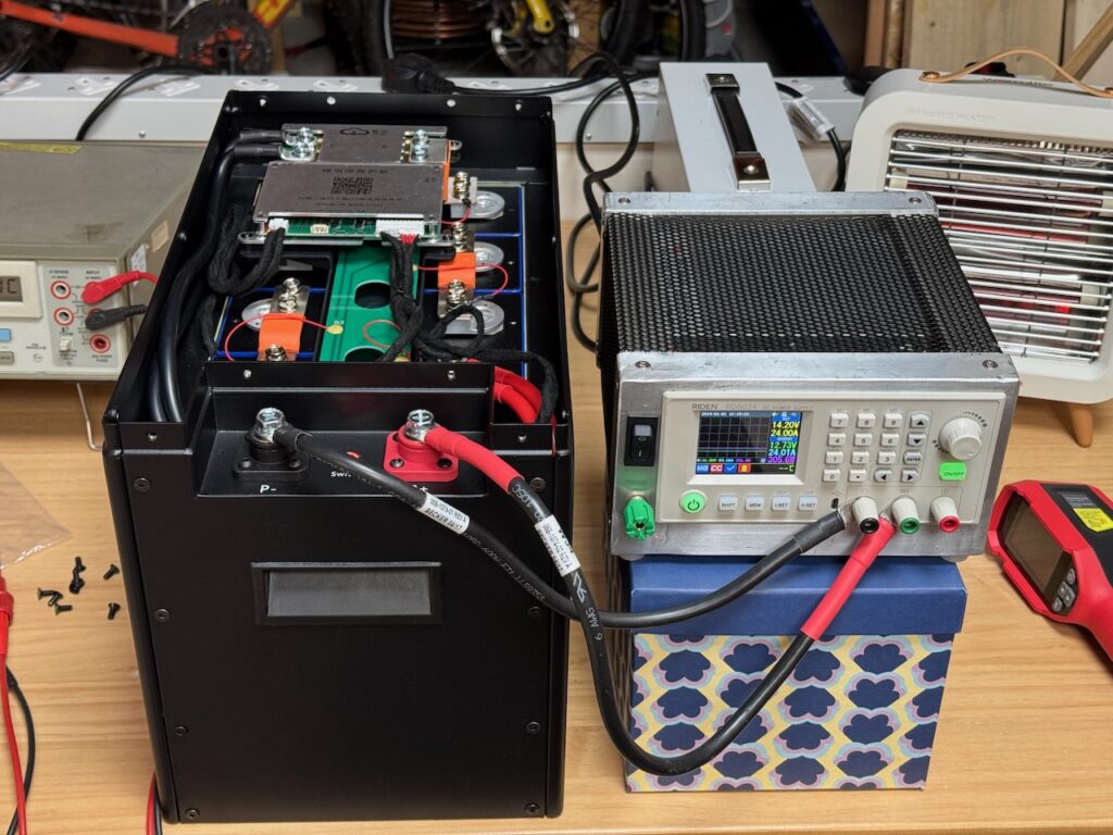
    Screenshot

    With 24A into an almost completely empty 314Ah battery, the first charge took rather long. When I came back the next day it had finished, and both the Riden and the BMS showed almost exactly 314Ah input to the battery.
    Screenshot

    Which was oddly satisfying πŸ™‚

    All in all, this is one serious piece of Chinesium. The cells were brand new with no signs of previous use or tampering with the QR codes. They were very well matched and delivered exactly the advertised capacity. The BMS worked out of the box and its voltage, current and capacity measurements were reasonably accurate.

    And the kit came from a UK dealer and has a warranty! It hardly even qualifies as Chinesium, except that the cells and BMS are so proudly made in China. Did I mention that China absolutely cornered the market in LFP?

    It just misses out on the highest grade because there was no documentation whatsoever. Like none.

    πŸ€„οΈπŸ€„οΈπŸ€„οΈπŸ€„οΈ Reactor grade Chinesium

  • Bluetti AC50B review and teardown

    [In this episode of The Chinesium Mine we can’t resist the urge to dismantle the new power bank]

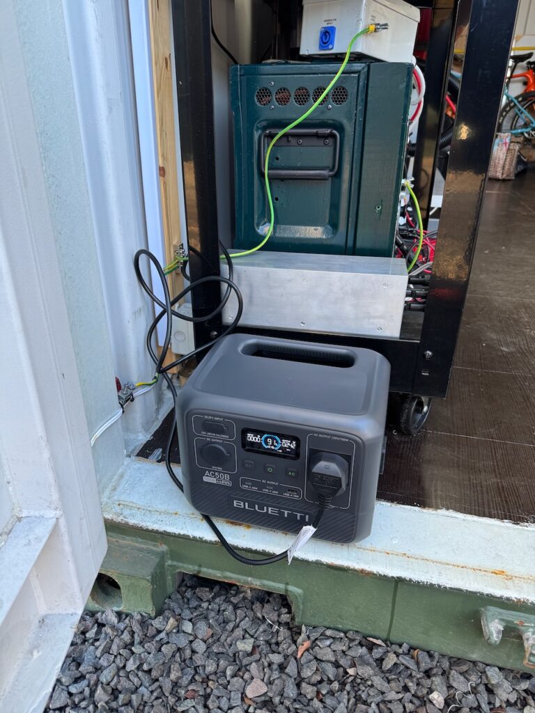
    During my stay at Container Labs I got a Bluetti AC50B in the Black Friday sales. It was very useful as a kind of bucket of electricity that could be charged at home and used to recharge the main batteries on site.

    I liked the Bluetti because it was cheap, used the safer LFP chemistry, and would accept a 230V AC input directly, unlike many other brands that need an external power brick to charge off mains. During my time at Container Labs it worked reliably and appeared to meet its advertised energy, power and runtime specs (700W, 448Wh) just fine.

    As usual I couldn’t leave it alone and had to mess around with it.

    AC UPS functionality

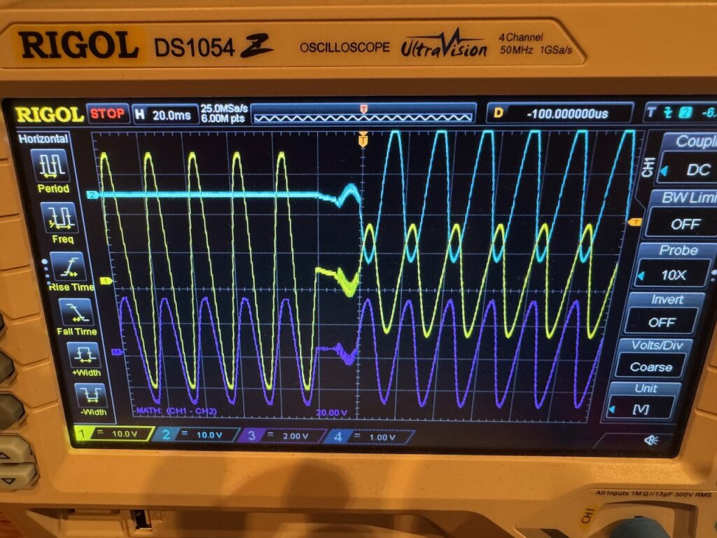
    I checked out the behaviour when used as a UPS, by hooking up oscilloscope channels 1 and 2 to the live and neutral outputs from the front panel AC outlet, and connecting and disconnecting the mains input.

    This scope shot tells us a lot about how the unit works inside. Even before taking it apart, we can see that it must use a bidirectional inverter/charger to transfer power between the AC side and the battery.

    When AC mains is connected, it is passed through to the front panel outlet, and the inverter/charger charges the battery. The changeover of the front panel outlet from inverter to mains is seamless, as it synchronises to the mains frequency/phase before toggling the relay.

    When the mains is disconnected, it quickly switches over to inverting mode. The switch back to inverter on loss of mains entails an interruption of about 20ms, a bit more than a dedicated UPS, but I’d be surprised if any load would be upset by this. I tried it several times and chose the worst looking transfer for my scope shot.

    So overall it’s quite usable as a UPS. And they even used a double pole relay to change over both live and neutral. Some cheap UPSs only change over the live, and can feed voltage back into the neutral pin of the plug after it’s pulled out of the wall.

    1 point for UPS functionality and not needing a power brick.

    Other AC trivia

    The output frequency is selectable as 50 or 60Hz in the Bluetti app. As I tested software in a previous life, I tried setting it to 60Hz before plugging it into our 50Hz mains. The unit wasn’t bothered, the frequency simply ramped down to 50 as part of the synchronisation process, and remained at 50 the next time mains was disconnected.

    The power quality is decent, like most “true sine wave” inverters the waveform looks closer to a sine wave than the actual mains supply. (though again like most inverters, it’s easy to mess that nice waveform up with a nonlinear load)

    With the inverter turned on but no load, the runtime displays as 41 hours. We can infer an idle power consumption of about 11W.

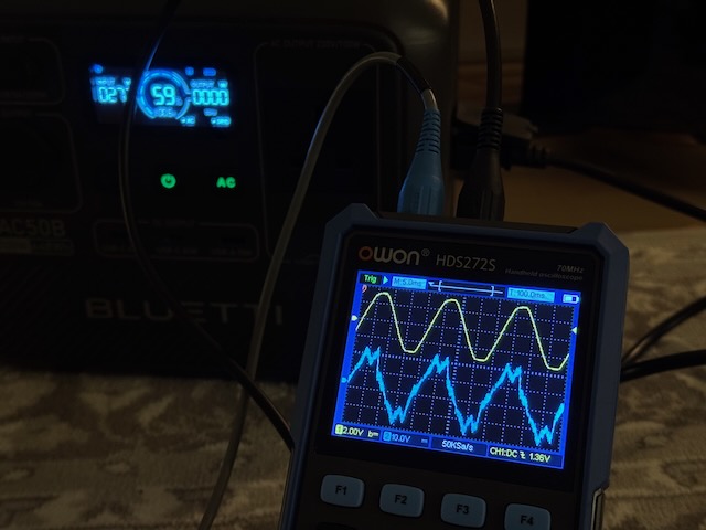
    I also had a look at the current drawn from the mains when the unit is charging. Not the most sinusoidal, and a bit noisy, but it’s definitely making some kind of effort at power factor correction. (blue trace is current, yellow trace is mains voltage for reference, at 275W charging power)

    Charging from the Lister diesel generator was also a success. It would drop out when a heavy load was removed from the generator, but always restarted.

    Teardown

    Next I took it apart. 1 point for not having any “warranty void if removed” stickers πŸ˜€

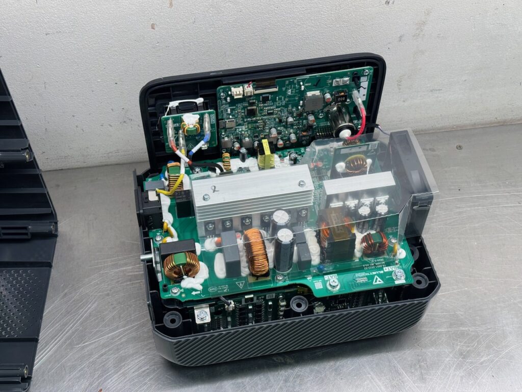
    The build quality seems surprisingly good. The battery proper is in the bottom of the case. It looks like a bunch of large cylindrical cells.

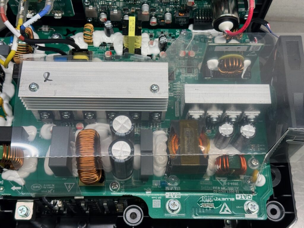
    Most of the power electronics is on this PCB. Below the 2 large heatsinks we can see the circuitry for the inverter, which matches my earlier guess of a bidirectional inverter/charger.

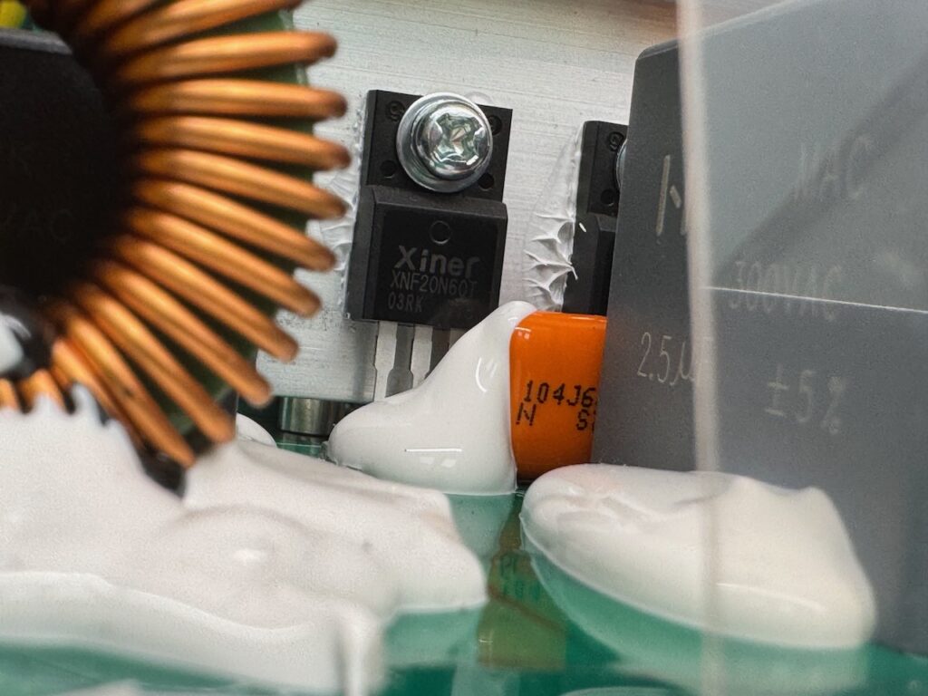
    On the left heatsink we can see 6 XNF20N60T IGBTs from Shenzhen Invsemi. (Β£0.53 each if you buy 50.)

    4 of these IGBTs function as the inverter H bridge when inverting, and rectify the incoming mains when charging. The remaining 2 function as diodes when the unit is inverting, to rectify the high frequency output of the DC-DC stage. When charging, these act as a half bridge driver.

    On the right heatsink we can see a full bridge of 4 low voltage MOSFETs that drive the DC-DC stage when inverting. They must work as a rectifier when charging, but I didn’t figure out if they went to the extra hassle of synchronous rectification.

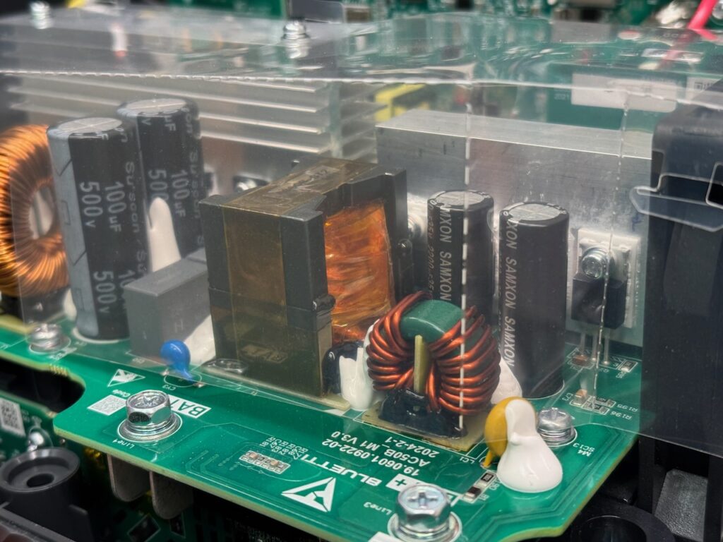
    The DC-DC topology is probably a LLC with the inductance integrated in the transformer, and resonant capacitors on the secondary side.

    I believe the vertical PCB above the MOSFET heatsink is the MPPT for the PV/DC input.

    A better view of the DC-DC converter transformer. Our old friend triple insulated Litz wire is doing most of the work here as usual. I couldn’t make out a part number for the MOSFETs.

    I found exactly one microcontroller in the whole unit. An Artery AT32F415RBT7. This is an ARM Cortex-M4 with 32K of SRAM, 128K of flash, a 2MS/s 12 bit ADC… Yours for $0.99 in quantity 50.

    (It wouldn’t surprise me if there was another controller chip of some kind on the underside of the power board, but I didn’t dismantle that far.)

    I was fairly sure everything in this unit would be Chinese, but Artery are actually Taiwanese. Their chips seem heavily inspired by the STM32.

    Smart functionality

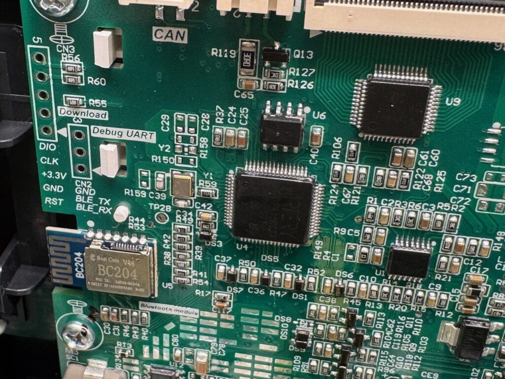
    We can also see a Bluetooth module in this pic. The Bluetti smartphone app works fine, but there’s absolutely no security or pairing process. You just install on your phone and connect to any Bluetti within range.

    Minus one point for cybersecurity. I’m sure if I took this to a seriously nerdy event like EMF it would be hacked and remotely self-destructed in 5 minutes. Todo: figure out how to add a switch that disables the Bluetooth.

    Direct battery output?

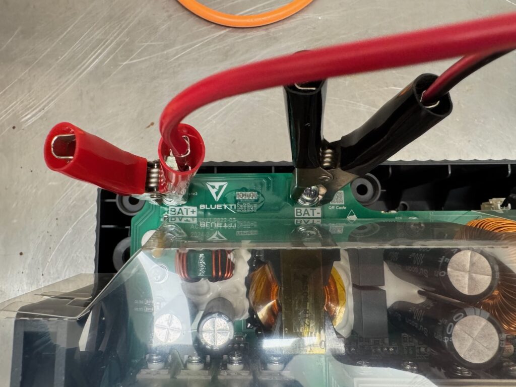
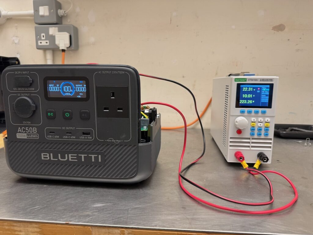
    I couldn’t resist trying to draw power directly from those clearly marked BAT+ and BAT- terminals.

    It worked, I was able to max out the electronic load and the Bluetti didn’t complain. At 22.3 volts, we can guess the battery must be 7 LFP cells in series.

    The output power display showed 0 and the runtime remained at 99.9 hours the whole time, but the SOC display started to decrease. Half a point for “expandability” πŸ™‚

    Only half a point because I suspect something awful would happen if these terminals got shorted out or the battery was drained completely through them.

    DC inputs and outputs

    The DC/PV input is an XT60 connector. Bluetti supply two adaptor cables: a cigarette lighter plug, and a MC4. I tested it with 12 and 24V power supplies and it measured up to the rated 8.5A and 200W. I didn’t actually try it with a solar panel.

    The 12V cigarette lighter output is 12.0V exactly and has pretty much no overload capacity. It trips off just above 10A even for short pulses. of current draw. This is to be expected considering that it’s derived from a 24V battery with a DC-DC converter, and I haven’t had any trouble with it in practice: the highest powered device I have that plugs into a cigarette lighter outlet is a 12V air compressor, and it ran that.

    The USB ports work as expected. The USB-C ones will run a laptop and charge DeWalt tool batteries.

    One point for comprehensive DC connectivity, and for not having any barrel jacks (aka DC5521)- arguably the worst DC power connector in the world!

    DC UPS?

    Would it work as a DC UPS to power Raspberry Pis and the like from the USB ports? I can’t say for sure that it doesn’t have some evil quirk that would stop this working, but I didn’t see any issues.

    It can charge from AC or DC while powering DC loads. There is no float stage to the charging. The charger toggles on and off and the battery micro cycles between 98 and 100%. Or maybe it was 95 and 100%. Either way it seems like a reasonable charging algorithm, given that lithium batteries don’t like being held at high voltage indefinitely.

    I also didn’t observe any overzealous auto shutdown of the DC outputs if the load didn’t draw current for a long time.

    Conclusion

    All in all, this is a perfectly good power bank. The only thing that leaves a slightly cheesy taste in my mouth is the “Power Lifting” feature, which is claimed to allow the unit to run appliances rated up to 1000W. It does this by simply letting the output voltage sag to about 200V under heavy load, so a resistive load that would draw 1000W at 230V only draws 700.

    So as an engineer I feel cheated, but as a human being, I got coffee and porridge from this 1000 watt travel kettle (drawing 715W as you can see) Grudgingly then I give it an extra half point for the “Power Sagging” feature.

    The final verdict: with 4 points this is

    πŸ€„οΈπŸ€„οΈπŸ€„οΈπŸ€„οΈ Reactor grade Chinesium

    A genuinely innovative product developed in China. The Chinese might not have invented the portable power station genre (that credit probably goes to the American founders of Goal Zero) but they surely have designed some nice units.