[But it did. Extending your diesel heater control panel]
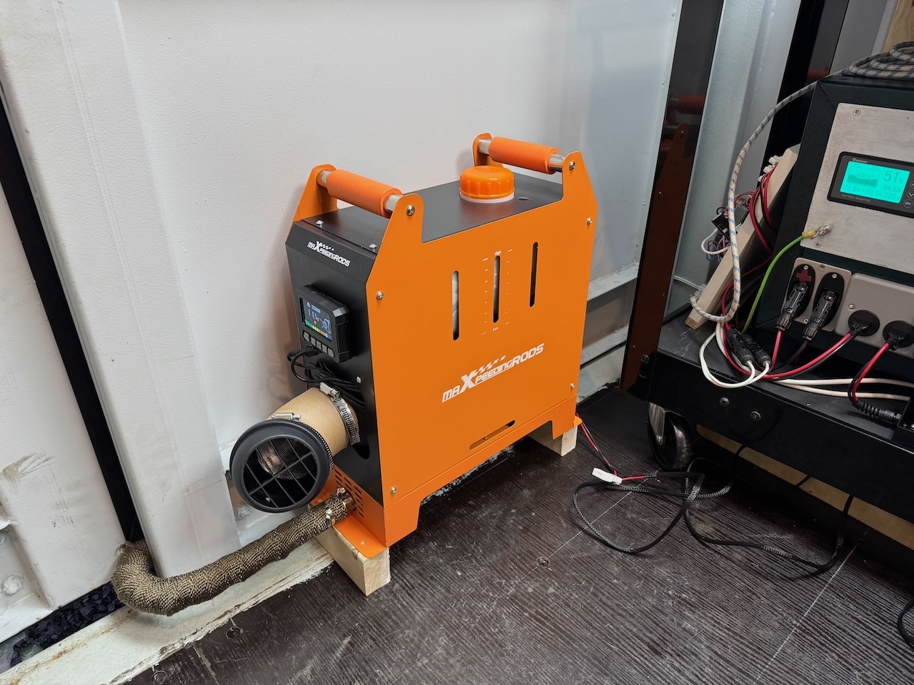
When I moved into Hayburn Labs, the diesel generator had to go, but my trusty (ish) MaxpeedingRods diesel heater came with me. I thought it was worth keeping as the running cost is about half of an electric heater.
There are dozens of brands of these devices, all Chinese clones of the Webasto air heater, priced at about one-fifth of the real thing. The real Webasto and Eberspacher heaters are sold as bare units for permanent installation in a vehicle, with the combustion air inlet and exhaust routed directly to the outside. But some Chinese entrepreneur came up with the idea of mounting the whole system together with its fuel tank into a portable box, with the combustion exhaust through a short length of pipe to nowhere in particular. This package proved quite popular and it’s now even possible to buy a European made version, the Autoterm Travel Box 2.
Mine must be one of the better clones as it hasn’t caught fire or gassed me with carbon monoxide. Yet.
For now combustion air is drawn from inside the building, and the exhaust pipe is poked through a hole in the wall. As I’m doing the place up (and making it more airtight) I plan to relocate the heater outside for safety, and it would be nice to extend the cable that connects the heater to the control panel. I haven’t seen much information about this online, so I’m documenting my experiments here.
According to the intertubes, all of these heaters have a 3 wire connection with a low-speed digital data link similar to the automotive LIN bus.
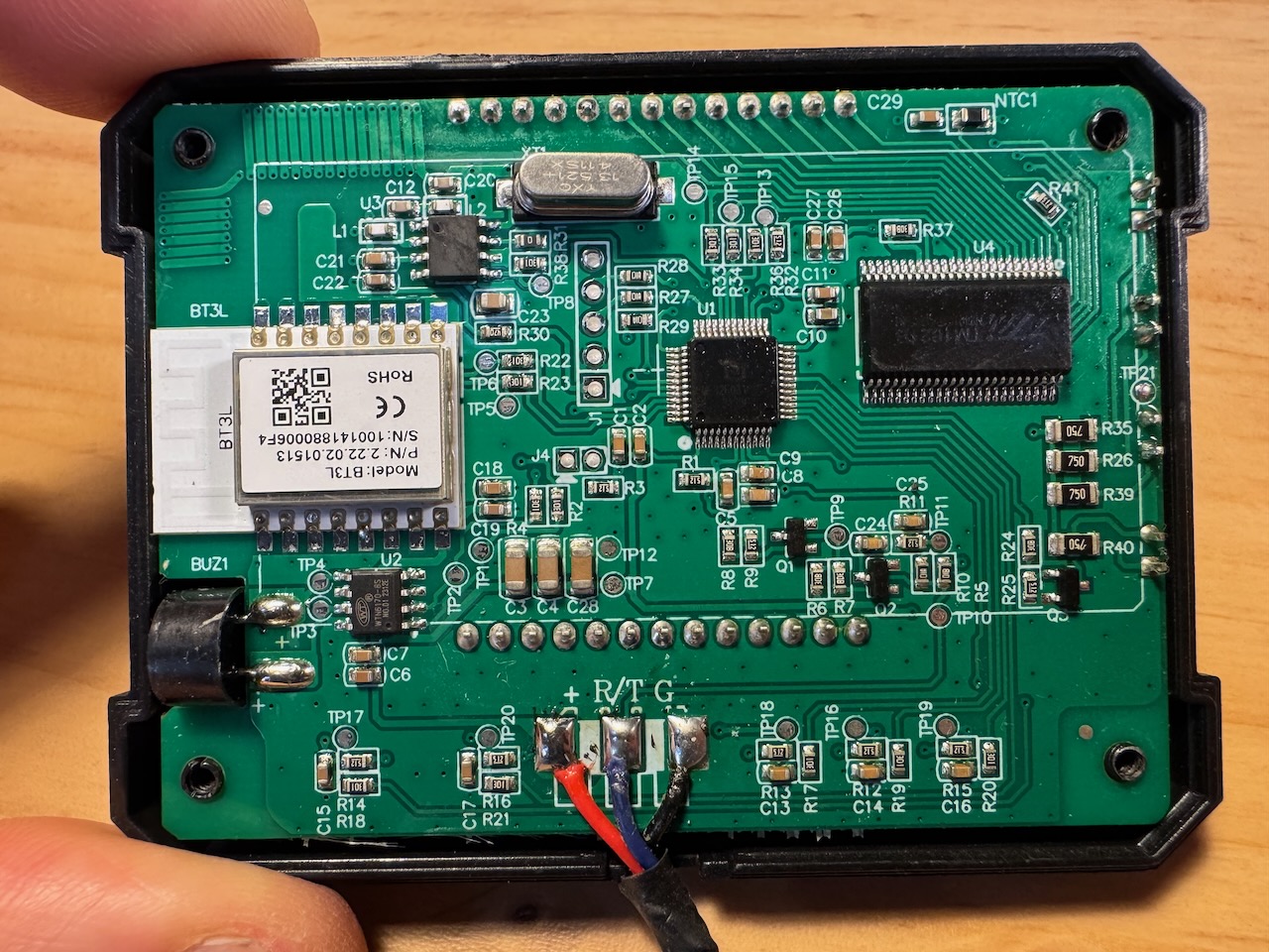
On opening the control panel, sure enough I found 3 wires marked +, R/T, and G, which I guess are positive supply, a bidirectional data line (Receive/Transmit?) and ground. Real LIN uses 12 or 24V for both power supply and signalling, but according to the manual, this is 3.3V. (yes it has a printed manual in legible English)
You can see from the PCB that it has both Bluetooth and 433MHz wireless remote functionality, and it came with a remote that works, so why am I even bothering to extend the wire? Well the temperature sensor for the thermostat functionality is on this board. Probably “NTC1” in the top right corner. So I think it makes sense for it to be in the main work area.
I unsoldered the three wires from the control panel PCBA, snipped a Cat5 patch cable in half and attached the two half-cables with the following colour code:
| Signal name | MXR wire | Cat5 wire |
| + | Red | Orange, orange/white |
| R/T | Blue | Blue |
| G | Black | All other wires |
As a Cat5 has 8 cores, I had 5 left over so I used several in parallel for the positive supply and ground. I thought this would help with voltage drop and noise pickup if it really does use 3.3V levels.
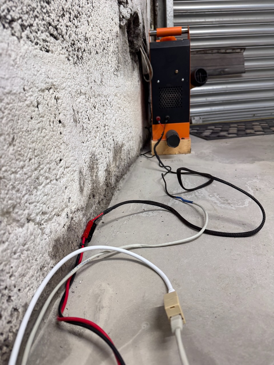
I plugged the two ends together with a RJ45 coupler, and the panel lit up and still seemed to work. So for my next test I interposed a 15m Cat6 Ethernet cable.
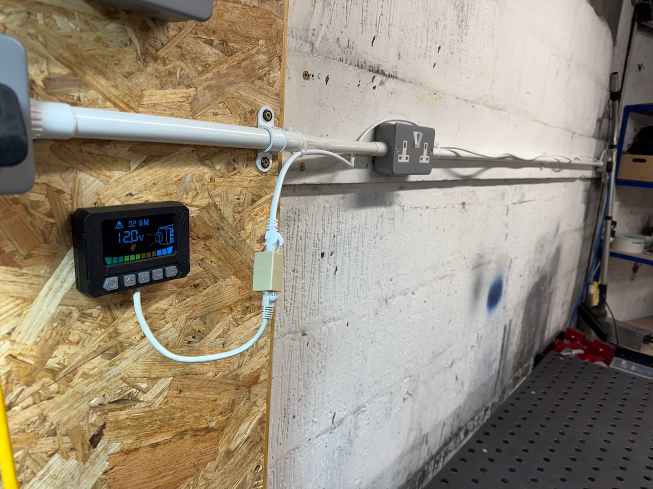
It still worked…
Discovering what happens when the control panel is unplugged with the heater running is an exercise for the reader. A reputable manufacturer like Webasto would of course have tested this and made sure it went through its normal cool-down and shutdown sequence. I wonder if the Chinese clone makers have that much attention to detail.