More detailed information on how my TC was built. See also TC Theory
Transformer |
|||||||||||||||||
|
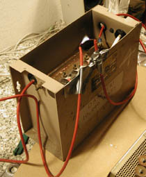
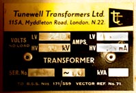
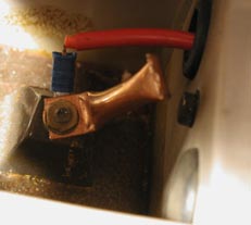
I used a 10kV, 25mA neon sign transformer, made in England by Tunewell Transformers. I didn't choose this particular model of transformer for any reason: it was given to me by a friend who found it in a skip (dumpster) Since this was the first part I got, I designed the TC around it. I measured the leakage reactance and chose a primary capacitor to resonate with it. (Resonant operation doesn't quite give the maximum power throughput, but it gives the highest charging voltage, so the smallest spark gap losses) Then I could calculate the voltage the capacitor would charge to. I needed to know this in order to design the spark gap. At a later date, I added a safety gap between each terminal of the NST and ground. I made them from bent and flattened pieces of copper tube.
Measurements/calculations
|
|||||||||||||||||
Tank capacitor |
|||||||||||||||||
|
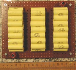
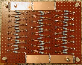
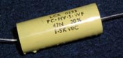
Some ingenious folk make capacitors out of beer bottles, plastic cups, pieces of polythene, panes of glass, and other junk. I wanted the best performance so I made a Multi-Mini-Capacitor (MMC) which is a whole lot of small capacitors connected in series-parallel. You have to use quality plastic film capacitors with a pulse rating, otherwise they'll probably blow to pieces or catch fire. I chose 47nF 1500V caps, pulse rated 1000V/uS, made by LCR, which I bought from Farnell in England. (part #106-372) I calculated that I needed 9.4nF, so I made three series strings of 15 caps, and put these in parallel, to give 9.4nF exactly. Since a capacitor bank like this can store enough energy to kill you, I fitted a 10MOhm bleeder resistor across each cap. Ordinary 0.25 watt resistors can't stand the voltage in this application, so I bought special resistors with a 3,300 volt rating (Farnell part #341-850)
Note: When designing, I ignored the manufacturer's AC rating for the caps, and used the DC rating instead. Most builders of MMC caps seem to do this with no problems. I put the 45 caps together on a piece of fibre board which I found in the junk pile. Notice the way I wired them, the voltage increases smoothly from one end of the board to the other, and the terminals are spaced far apart. This is important because it will be running about 15-20 kV and that can arc a fair distance. I used two strips of copper PCB material to parallel the cap strings together.
|
|||||||||||||||||
Spark gap |
|||||||||||||||||
|
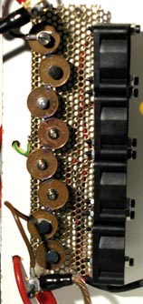
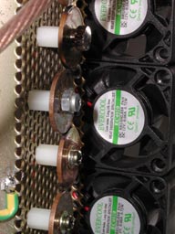
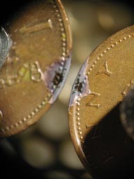
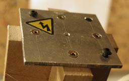
There are plenty different kinds of spark gap you can use, all the way from two bolts, to a full-on rotary. I wanted to use a multi-section gap, but instead of the usual RQ type (also known as TCBOR after the Tesla Coil Builders Of Richmond who invented it), I made my own version out of one-penny coins. These coins are solid copper so they dissipate heat well. And being flat, they're easier to mount than the pipes that make up an RQ gap. I drilled a 3.5mm hole in the middle of each coin, and screwed them to some nylon standoffs. Best to use the kind with a hole in one end and a nylon threaded stud at the other: I reckon if you put a metal screw in both ends it would arc over. For a baseplate I used a piece of perforated metal (part of an old power supply casing) that had holes of the right size and spacing. I bent one end up and bolted on four mini cooling fans from a Hard Disk Cooling Unit (Maplin part #UY81) The air draught stops it overheating and melting the plastic standoffs, and also helps to quench the discharge quicker.
I experimented with placing the coins in different arrangements on the baseplate until I got a decent-looking gap between each pair. I tested it by hooking the NST up to it and seeing how many gaps it could light with its 10kV output (14kV peak) It could just barely light 5, so I inferred that the breakdown voltage was (14/5)=2.8kV per gap. I run with 6 gaps at the moment, so it should fire at 16.8kV. There is a 7th gap that I could connect in, which would take it to 19.6kV. The NST can theoretically charge the tank cap to 20.0kV every half cycle, so 7 gaps is the absolute limit. I haven't taken it to 7 because I don't know how accurate my calculations are and I don't want to wreck the NST with excess voltage.
The plastic supports haven't melted so far, but the coins are looking burnt at the edges. Some builders make their spark gaps from tungsten welding electrodes which are indestructible... Where can I get some of those? The fans were originally powered from a cordless drill or laptop battery. This wasn't a very neat solution so I added a small transformer/rectifier (the guts of a 12 volt unregulated wall wart power supply that I cut open) I connected it to the mains input of the NST, so I didn't have to bother with two mains supplies to the coil. The fans only spin when the coil is firing but this doesn't seem to be a problem. |
|||||||||||||||||
Primary coil |
|||||||||||||||||
The primary coil design was determined by five things:
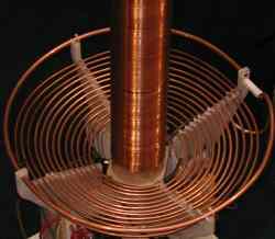
The inductance depends on how many turns you use, and the dimensions of the coil. I put together a spreadsheet that would calculate the inductance if I keyed in the number of turns, the winding pitch, and the coil mean radius. (I used the Archimedean spiral formula from Matt Behrend's website) I dinked around with it for about half an hour until I got a coil that met all the requirements. You can download calculator programs like this from the web (link) My finished design had 13 turns on a 10mm (0.4") pitch, with an internal diameter of 130mm (5.2") and an outside diameter of 375mm (14.8") The inductance was 45.5uH: I made it a little more so I had room for tuning. I also gave it a slight conical shape to increase the coupling. I added a strike rail made of 10mm copper tube. I inserted a 1" teflon standoff to stop it from being a shorted turn. In hindsight, the strike rail was not necessary. The sparks aren't quite long enough to reach it, and what's more, they always seem to come out sideways or upwards. I have never seen this coil send a single streamer downwards. |
|||||||||||||||||
Secondary coil |
|||||||||||||||||
|
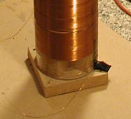
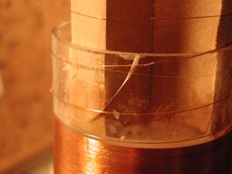
The secondary coil was based around a plexiglass tube. There were a few different sizes available, and I chose what looked like a reasonable size. This was the first part of the coil I made and with hindsight I would have made it smaller. I wound it by getting someone to spin it with a cordless drill while I wound the wire on. My biggest mistake was doing this while the first coat of varnish on the tube was still wet. I ended up with a number of uneven spots in the winding where I made a mistake and couldn't repair it, including one spot where the wire crossed over itself. I made sure this flaw ended up at the bottom where the voltage would be lower.
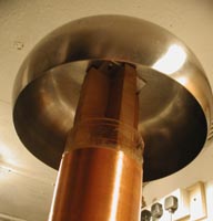
Once the coil was wound I applied two more coats of insulating varnish, and let it dry for a good long time, OK, eighteen months! (I lost interest in the project for a while) Next I sealed the ends with plexiglass disks. I made these from a sheet of plexiglass, using a hacksaw and file to shape them, and stuck them in place with two-part epoxy glue. Using 18mm MDF board, I made cross-shaped inserts for the top and bottom of the tube, and stuck these in with epoxy. To the bottom insert I screwed a 90mm square base. To the top one I screwed a small aluminium plate which would be the mounting for the topload. The windings of your TC secondary should finish somewhat below the bottom of the topload. So I made the top insert extra-long. You are not supposed to take the wire directly up from the last winding to the topload, but instead wind it round in five or six extra widely-spaced turns. This supposedly helps to reduce voltage stress and corona on the top turns. Of course, it's even better if you can avoid dropping your finished secondary and cracking the tube.
Measurements
| |||||||||||||||||
Other |
|||||||||||||||||
|
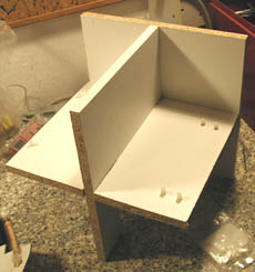
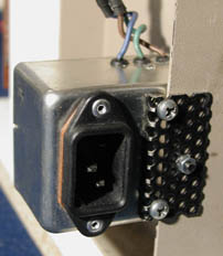
I assembled all the parts on a frame made from three pieces of particle board (chipboard) which I fixed together with chipboard screws. The frame holds all the parts together securely so that the TC can be picked up and moved around easily. I made sure to leave a good clearance between the transformer casing and the primary coil, so the steel casing didn't soak up any of my precious RF power.
The high-voltage wiring passes through holes drilled in the frame, so that the wires can't move around and touch things they shouldn't. This is especially important with the hi-fi speaker cable I used to wire the primary circuit: the insulation on this cable isn't meant to take 20kV. The neon transformer originally just had a cord hanging out with a plug on the end. I ran the coil by plugging it into an extension lead, and using the switch on the wall socket to operate the coil. This wasn't unsafe, but it was a pain in the butt. Later, I added a power line conditioner with built-in IEC inlet which I had lying about. My TC now had no power cord so I made an extra-long cord with a push-button switch. The switchbox has a red light to let me know the system is powered and ready to fire, and also its own IEC inlet to bring the power in. I get into the habit of pulling the plug out of this after every run, it's not a problem because the plug is right there at the box. I reckon this zapper box is a good idea. It improves safety because power is cut in two places before I tinker with the coil, and the push button is momentary so it's easy to turn the apparatus off in a hurry. What's more, the big red button brings a cool nuclear destruction vibe to my Tesla coiling activities. |