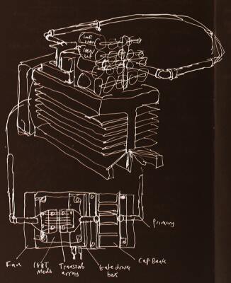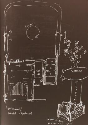

So everything must be laid out to absolutely minimise the inductance. As much of the inductance as possible should be 'on-axis', that is, coupled to the secondary. And it should be symmetrical to ensure that both IGBTs share current. Unfortunately, it also has to fit requirements for clearance- the primary must not be too close to the secondary, and there should be nothing pointy sticking up too far where it could attract arcs from the toroid. These requirements are quite hard to reconcile and I had a number of tries only to rip it up and go back to the drawing board.

|

|
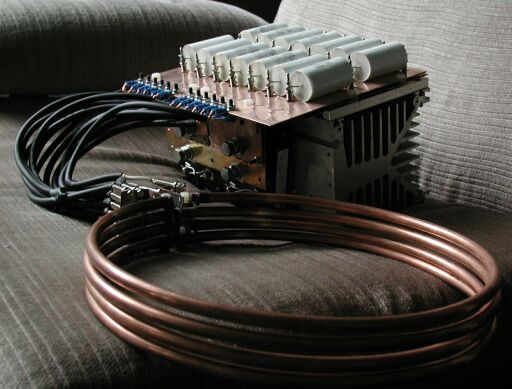
One day, while I was reading a paper on electromagnetic metal forming, inspiration hit. Instead of crowding everything around the secondary, I could build the coil separate from everything else, and connect it with a low-impedance transmission line. This is how metal forming machines channel the power from a car-sized capacitor bank into a coil the size of a dinner plate.
The transmission lines in these machines were made from several coaxial cables in parallel. Coax has reasonably low inductance to start with because the outward and return current paths are so close together. I figured that with 12 cables in parallel, each 10" long, the inductance would be around 0.002uH, small enough to ignore completely. In fact, I didn't need to use that many on the grounds of inductance, but I wanted to make sure the resistance was low enough.
I actually managed to source special high-current coax cable, intended for speaker leads in PA systems. The core and screen are both 2.5 mm^2 cross section, much more than ordinary RG58. The insulation between core and screen was thinner, and made of PVC :-6 but I reckoned I could get away with it.
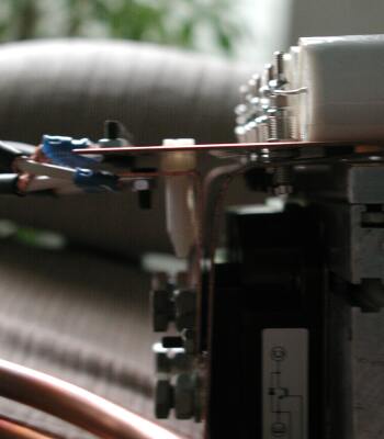
My next big brainwave was to use a laminated bus structure for the IGBTs and cap bank. This is basically two copper sheets separated by a gap of about 1.5mm. The outward current flows in one sheet and the return current flows in the other. The effective loop area is very small, so the inductance is small too.
My final trick, which I borrowed from one of Greg Leyh's designs, was to connect the MMC cap bank so that the currents in adjacent caps flowed in opposite directions. I hoped that this would reduce the ESL by cancelling the magnetic fields.

|

|
Read more about the tests on the next page.