
Now we know how fast we want to turn on, that's about 0.5us. We also know that Q=I*t. So we can say I=Q/t= 12 amps!!! OK All we need now is a 12 amp 30 volt gate driver. I designed this:
Basically it's a simplified half bridge made with MOSFETs. M1 is driven straight off the 555 timer. It turns the brick off, and also drives M2. How does this work? When the 555 turns M1 off, its drain is pulled towards 12V by current through R3. As M1 drain voltage rises, first D1 turns off, disconnecting M1 drain from the brick. Next M2 begins to turn on, bootstrapping itself through C1 as it does so. Within 500ns M1 is fully on and the output is high.
When M1 is turned on by the timer, the reverse happens. The drain voltage begins to fall, first turning M2 off, then pulling the output down through D1. Note both MOSFETs can never be on at once in this circuit.
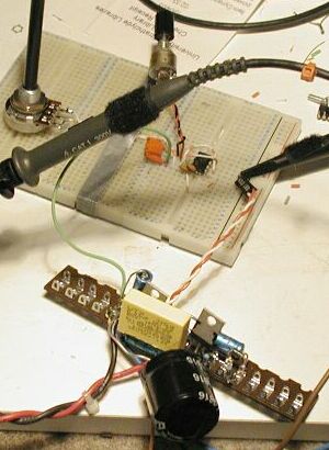
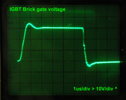
The ringing on the waveform is caused by the gate capacitance of the brick resonating with the inductance of the wires that go from the driver board to the brick. If you measure it at the driver board terminals, it's clean. Anyway, now we have a driver, time to test the brick out.