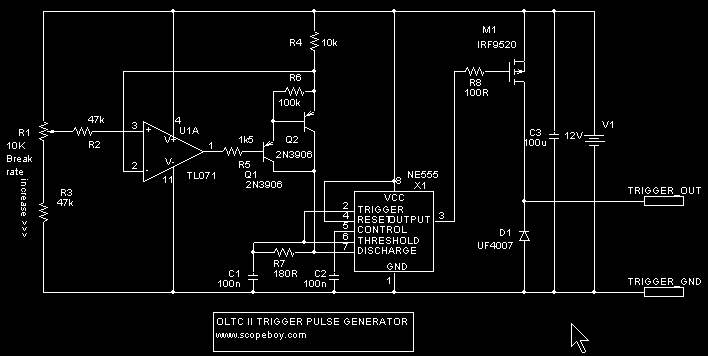


It is basically a 555 astable circuit, with the charging resistor replaced by a fancy current source circuit. This makes the range of adjustment very wide, in this case from 1 to 550 bps. This is similar to the trigger circuit in the Mini OLTC, but the current source is a more accurate op-amp circuit. So, for instance, if setting R1 fully clockwise gave 550bps, setting it halfway would give 225, etc, and a 10 turn dial with readout could be used. The single transistor current source in the Mini OLTC was pretty non-linear.
Note: Most op-amps won't work in this circuit because it requires input common-mode range right up to the positive rail. The TL071 is a fairly cheap/common op-amp I could find that fits the bill. There are others, but I happened to have a pile of 071s...
A MOSFET output stage has been added to allow sourcing of lots more current than the 555 alone could provide. This is necessary to drive the pulse transformers and cable capacitance while still maintaining a fast risetime. D1 provides a path for the pulse transformer magnetizing current.
The output goes to a 1:1 pulse transformer, which gives a floating balanced output. This is fed down Starquad microphone cable to another 1:1 pulse transformer at the receiving end. I used Starquad cable because of its high rejection of magnetic fields. The "pulse transformers" I used were common-mode line chokes taken from old switching power supplies.
This transformer isolation scheme gives galvanic isolation as well as interference rejection. Isolation is vital, because the chassis of the trigger generator is grounded, and the chassis of the IGBT driver is floating at -300V.