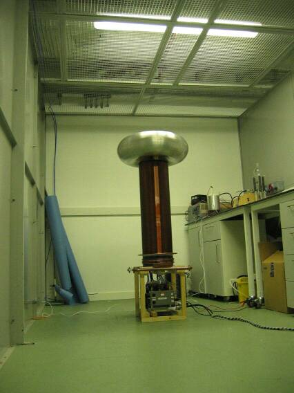

OLTC 2 set up in the Faraday shielded room
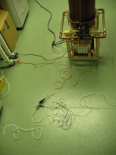
Every metal thing nearby was bonded to RF ground
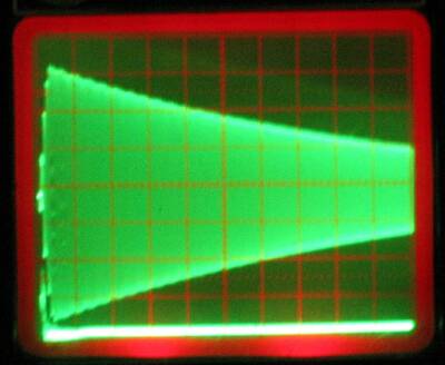
Waveform picked up by the E-field probe with no spark loading on the coil. The idea was originally to just remove the breakout point and keep the bang energy the same. But the bang energy had to be reduced by about 20% to prevent breakout from the bare toroid.
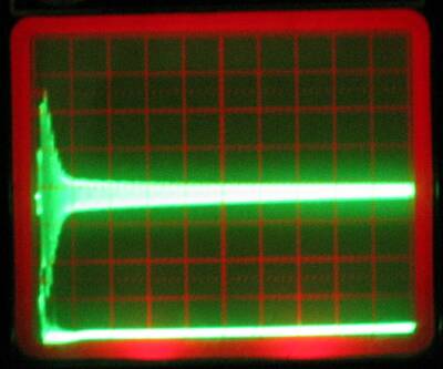
Waveform picked up by the E-field probe with the coil producing a 36" streamer at 100bps
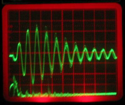
Same waveform as above but magnified. Note how unsteady the loading seems to be.
Also note noise pulses picked up on the bottom trace, these seem to be coming from
the discharge, as they appear even after the primary current has stopped.
However, the big bursts at cycle 1 and cycle 3.5 are probably switching and diode reverse recovery noise caused by the IGBT switch turning on and off.
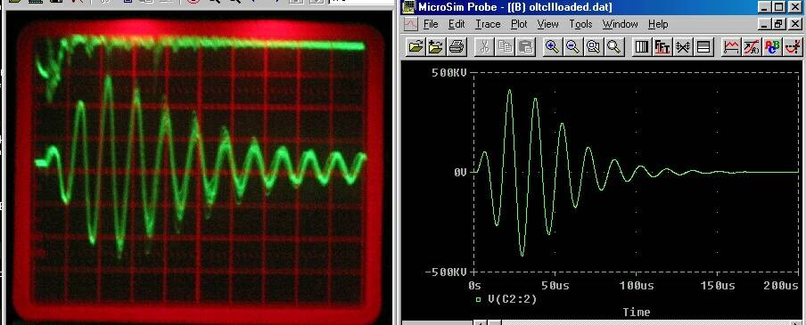
Attempt to fit a PSpice simulation to the measured waveform.
I also tried measuring the waveform (using pixel ruler in Photoshop) and calculating frequencies and log decrements. The PSpice simulation predicted a shunt load resistance of around 400k (capacitance unknown) but the simulation is suspect as the simulated coil has higher coupling than the real one.
The hand calculations showed a drop in frequency from 62.7kHz to 56.3kHz, and a loaded Q of 12. This suggests a loading of 992k in parallel with 7.3pF, which is equivalent (at the 63kHz measured frequency) to 108k in series with 8.1pF.
Using Terry Fritz's idea of a fixed resistance in series with (X pF per foot) I get 100k + (2.7pF/foot) which is not really anything like Terry's 220k + (1pF/foot). Are my calculations wrong? Is Terry's model wrong? Or are Scottish streamers just thicker and hairier?
I'll be repeating the experiment with different bang energies and break rates when time permits.