1950s Belling electric fire restoration

This winter I discovered that blocking up the fireplace makes the living room much warmer and cuts down the gas bill substantially. All good for the Conner Labs carbon footprint. πŸ™‚ However I guess an open fire has some sort of primeval appeal. Before I knew it I had bought this “vintage retro” piece of junk on Ebay.

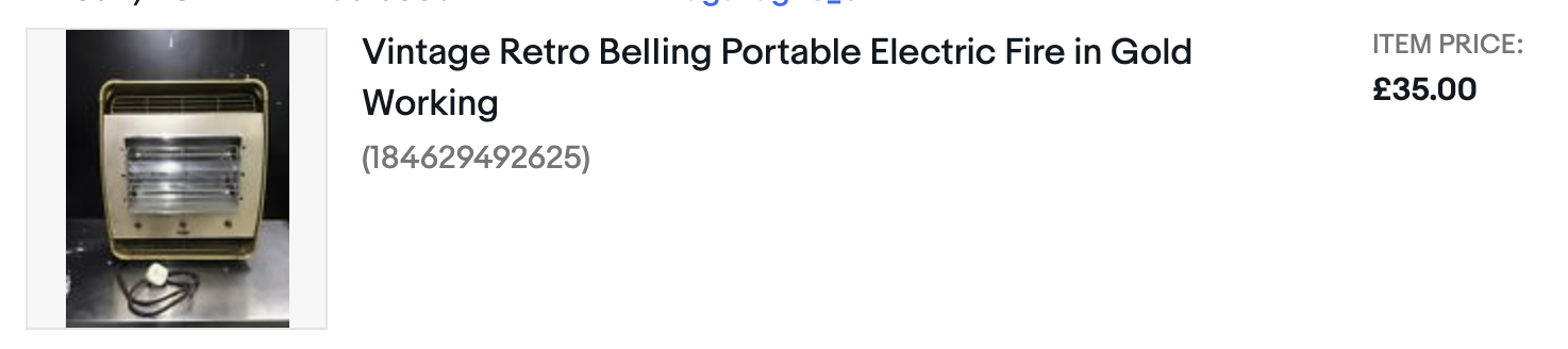
I immediately regretted it in case it turned out to be full of asbestos.

It was :/

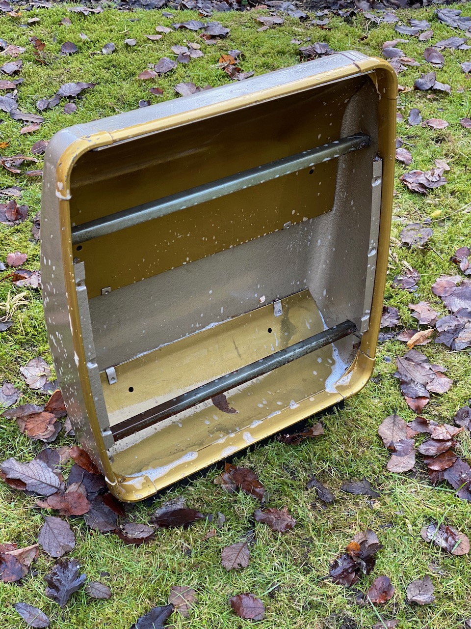
As it was also caked full of dust, and to be honest smelt a bit suspect, I decided to take it outdoors and wash it down with soap and water. Everything including the wiring, to get the asbestos wet for safe removal.

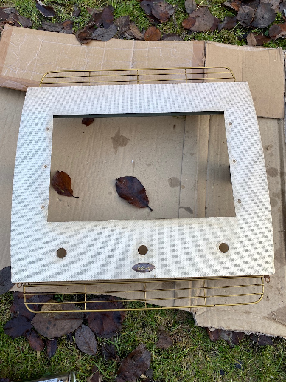
It was hardly the most complicated assembly so I stripped it down to the last nut and bolt and cleaned everything. The reflector was polished using T-Cut.

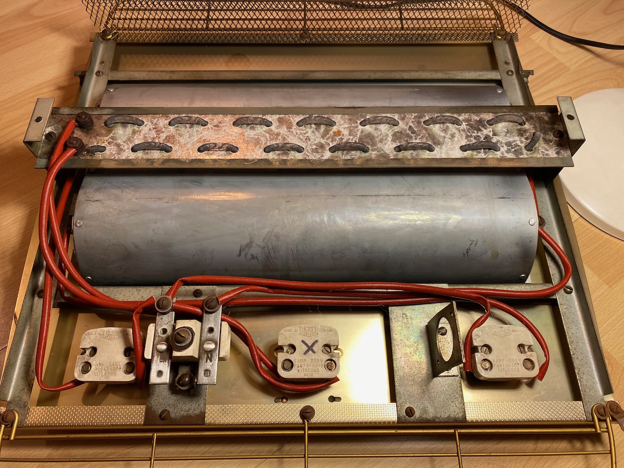
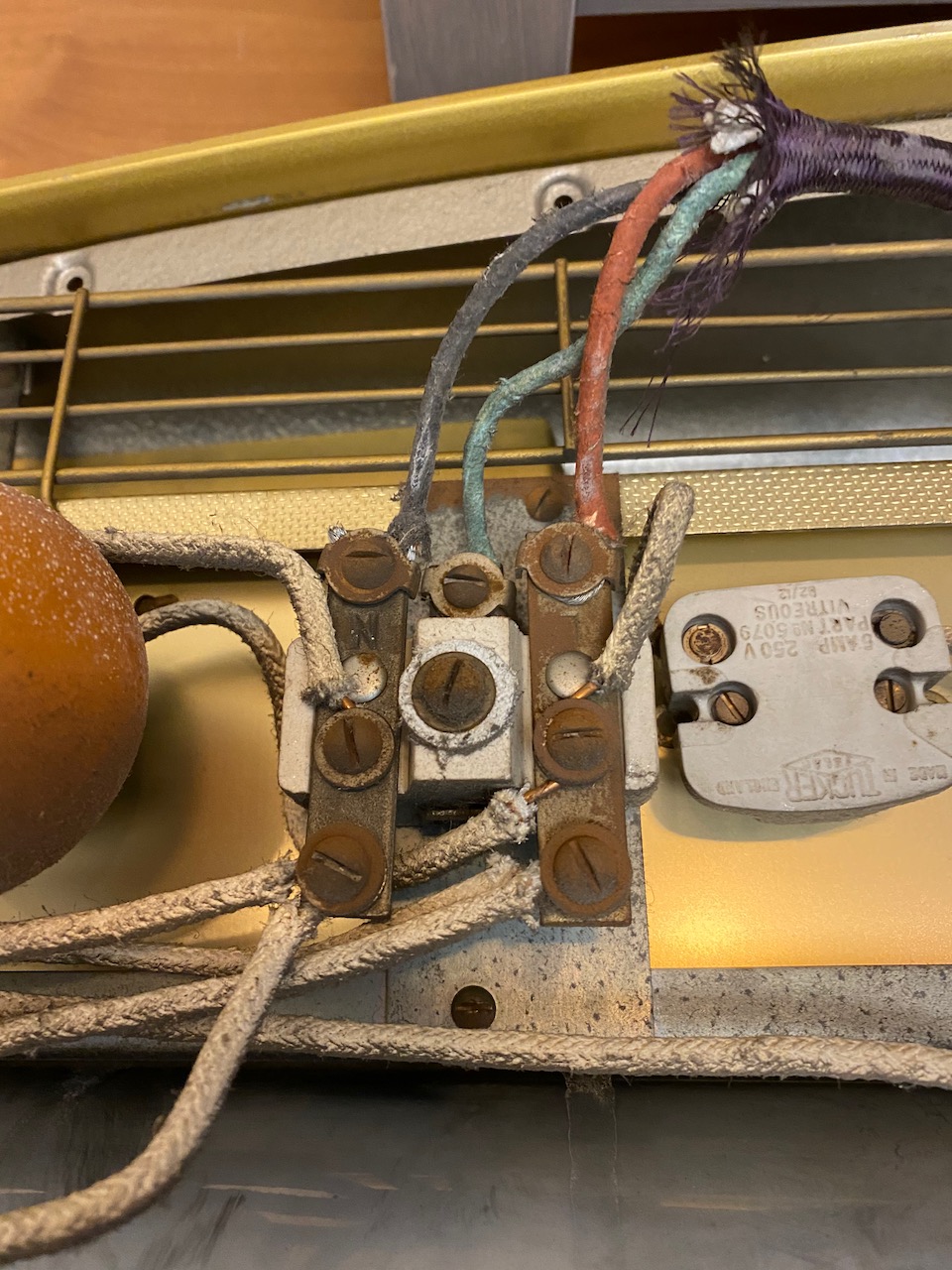
Rewiring with bare copper wire in modern high temperature fibreglass sleeving. The switch marked X had somewhat melted contacts. I couldn’t find a replacement so I retensioned them as best I could and used that switch on the lowest powered heating element.

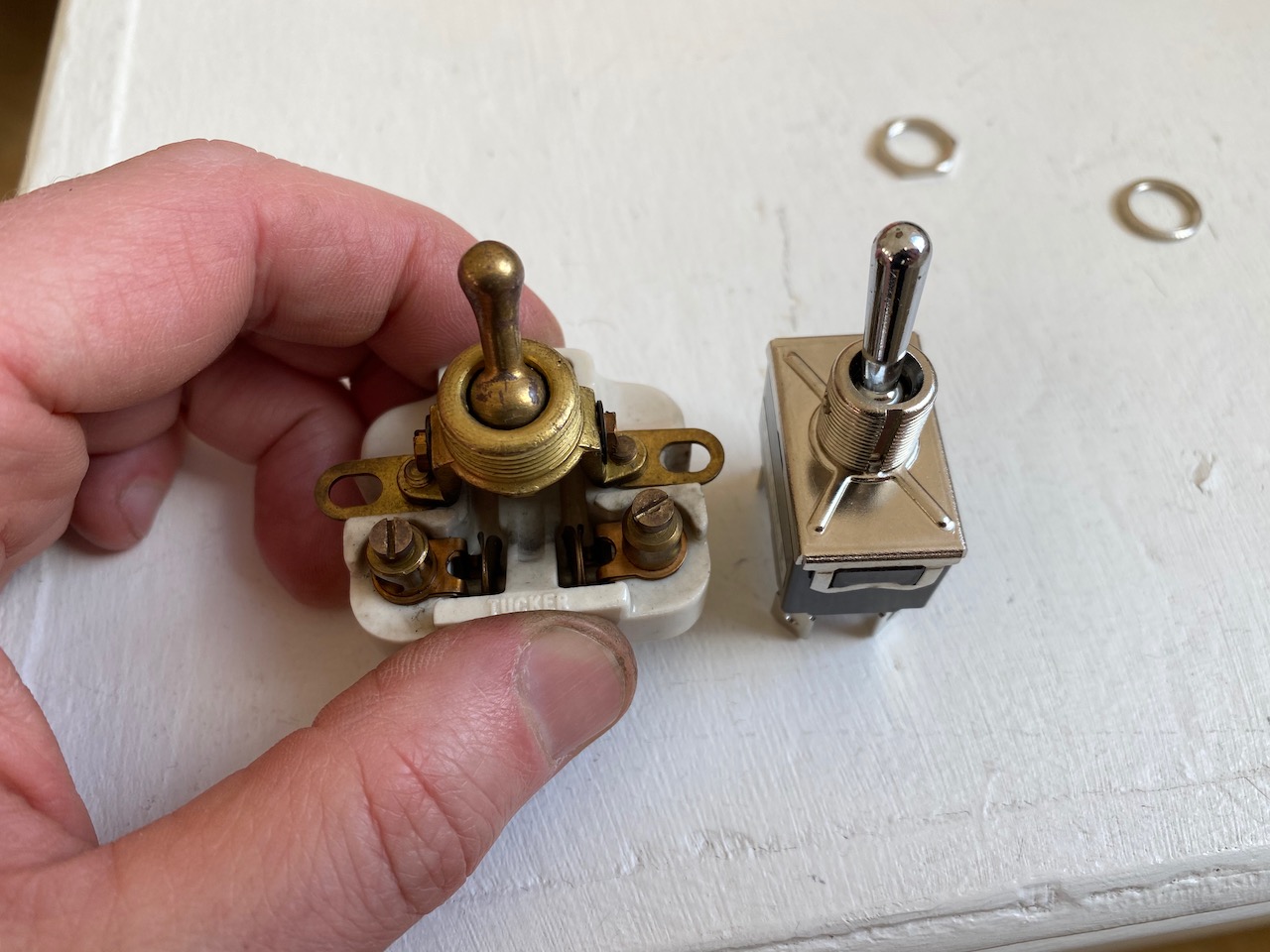
Modern toggle switch doesn’t have 1/10 of the vintage mojo. Doesn’t fit the panel hole anyway.

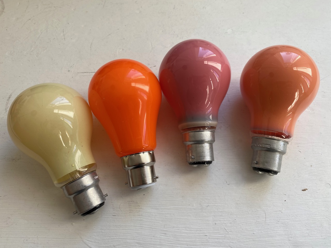
Red fireglow lamp is arguably the most important part πŸ™‚ 25W filament ones are still available.

About now I realised the error of using WD40 to free off the nuts holding the heating elements in place, as great clouds of WD40 flavoured smoke belched forth. πŸ™‚

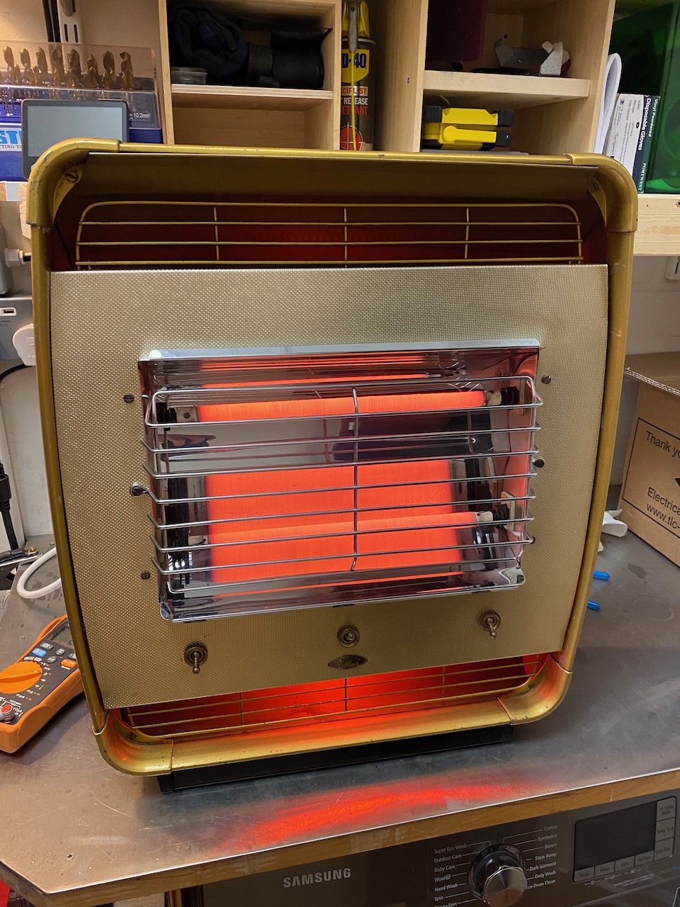
Once the fumes had dissipated it turned out to heat the living room better than the old gas fire and cost less to run.

12V lighting

One of the joys of living in an old house is dodgy wiring. Another joy is ornate lath and plaster ceilings that might collapse at any minute. πŸ™‚ My problem is a combination of the two. The overhead lights in most rooms are powered by 1930s vintage rubber and cloth covered wiring that can’t be replaced without trashing the ceilings.

As a token gesture to electrical safety, I added a RCD to the lighting circuit, and believe it or not it started tripping at random. This left me with a few options:

Stop using the ceiling lights altogether

Have them rewired and the ceilings replastered

Run the lighting circuit off a lower voltage that wouldn’t tax the ancient rubber and cloth insulation.

A lower voltage would of course limit the power that could be delivered before overloading the wiring. So the second part of the plan would be to replace the light fittings for LEDs to achieve a reasonable light output with less power.

I decided to go for 12V (in hindsight 24 would have been better- I ended up replacing the power supply with a 15V one as a compromise…)

First step was to source a reputable brand of power supply festooned with safety approvals. It will be left on 24/7 unattended, and it would be ironic to go to these lengths to avoid the wiring catching fire, only for the PSU to catch fire. πŸ™‚

I bought a few 600x600mm LED panel lights from TLC Electrical, and chucked the 240V drivers that came with them for some 12V drivers from Ebay.

They are still plenty bright enough.

The power supply was mounted next to the consumer unit and connected to the existing 240V lighting circuit with a FCU.

Oh dear… At this point I realised the thickness of the old wires was mostly insulation and the actual copper cross section was puny. To the point where a 11 amp power supply could potentially overheat them if one of the light fittings shorted out, leaving us no better off in terms of safety than before.

I connected it up anyway πŸ™‚

The first of the new light fittings in place

The other light fittings were modified with bodges like this

Later I added some fuses to address the issue of the PSU being able to overheat the wiring.

(footnote: this is still working in 2021 and I made some funky low voltage light fittings πŸ™‚ )

Tektronix 7603 mainframe repair

Last week I was given a big heap of surplus test gear. It included a Tek 7603 oscilloscope mainframe. I already have a R7603, so it was nice to get another one, but sadly it was sick. On applying power, it just sat there, dead in the water, with wisps of smoke coming from the regulator board.

First of all I downloaded the service manual from bama.edebris.com.

Then I noticed half of the power rails were missing, as was the 130V rail fuse on the regulator board. Someone had obviously been at it before me. I replaced this fuse, and it blew immediately with a sizeable flash and pop.

It turned out that several transistors on the regulator board had failed, some short, some open. I replaced the TO92 ones with 2N5551 (NPN) and 2N5401 (PNP) and the larger metal can ones with 2N2219s, except for one that looked like it needed to stand a higher voltage, so I got a MJE340 and jammed it into the socket. The smoke had been coming from a crispy-looking 1.2k resistor which I replaced too, even though it still measured 1.19k.

After doing this, all rails were correct, and the unit powered up. However ALT mode wouldn’t work. I replaced a 7474 IC on the logic board (with a 74LS74 as I had no originals) and that fixed it.

Then, the readout wouldn’t work. On closer inspection, there was no readout board: I suppose it must have been optional.

The focus was still a bit blurry with the focus knob cranked all the way, but adjusting the focus preset in the HV box cured that.

Last of all, the graticule lights wouldn’t work. Usually it’s because all the bulbs are blown, but this time it was because the cable assembly that drives them was missing, presumed lost by the last guy who tried fixing it. I found a similar 4-pin cable in a box of junk, and the lights came on.

Finally, just when I thought I was done, I noticed the channels were bleeding into each other in Chop mode. I tried replacing the other 7474, but it made no difference. In fact there was nothing wrong with the beam switching, the problem was that the Y amplifier wasn’t settling properly after each switch. Now a scope Y amplifier is a major piece of analog voodoo: it contains dozens of tweaks to compensate its own frequency response, and that of the delay line. My refusal to settle had a time constant of about 50us, though, and the slowest trim listed in the service manual was 50ns, not a lot of use. However the schematic also showed two networks for compensating slower “thermals”, and it turned out that the trimpot in one of these had gone open circuit. I replaced this and since there was no trim procedure in the manual, I just tweaked both networks for minimum bleed between channels. I got it better than my other 7603.

I love how you can take a 40 year old piece of Tektronix gear, and you can find the schematics and fix it in a morning with parts that are lying around the place. They just don’t make ’em like that any more. Now it’s time to have a go at the HP 141T spectrum analyser. πŸ™‚